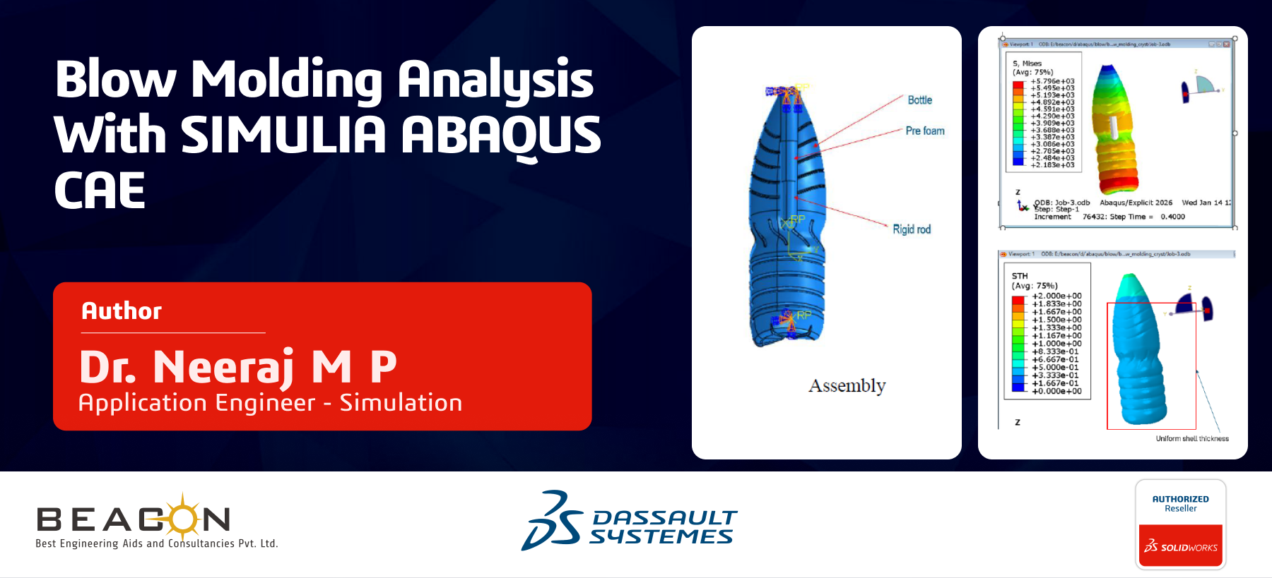


Blow molding analysis with SIMULIA ABAQUS CAE
Blow molding is a widely used manufacturing process for producing hollow plastic components such as bottles, containers, and automotive ducts, where the final product quality is strongly influenced by material behaviour, thermal history, and process parameters. Predicting thickness distribution during the inflation stage is particularly challenging due to large deformations, nonlinear viscoelasticity, and evolving material properties. Advanced finite element tools like Abaqus enable detailed simulation of such processes, offering insights into deformation patterns and thickness variation.
In this blog, two simulation approaches are presented for blow molding. The first uses a standard GUI-based setup, which provides a straightforward implementation but has limitations in capturing complex material physics. The second approach incorporates a VUHYPER user subroutine, where crystallization evolution is modelled to account for changes in material stiffness during deformation. By coupling the mechanical response with crystallization kinetics, this method more realistically represents polymer behaviour during stretching and cooling, ultimately enabling improved control over thickness distribution and achieving a more uniform final product.
The blow molding process is simulated using an Explicit Dynamics procedure in Abaqus to accurately capture the large deformations involved. Refer to images given below for the components involved in blow molding.
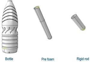
Prefoam, rigid rod and bottle die
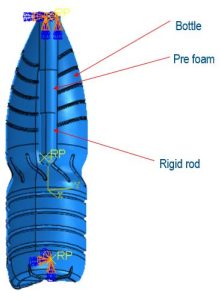
Assembly
In this approach, a rigid rod is first displaced to stretch the preform, representing the initial elongation stage. Subsequently, cavity pressure is applied to inflate the preform until it expands and conforms to the mold geometry. To enhance thickness uniformity, crystallization evolution is incorporated into the material model, allowing the polymer stiffness to evolve during deformation. This behavior is implemented through a VUHYPER user subroutine, enabling a more realistic representation of material response and improved control over the final shell thickness.
The preform material is modeled as a hyperelastic polymer using the Mooney–Rivlin strain energy potential to accurately capture its nonlinear elastic response under large deformation. The material constants are defined as input properties and passed into the VUHYPER user subroutine within Abaqus, enabling customization of the constitutive behavior, including the incorporation of crystallization effects. To ensure numerical stability during the explicit simulation, appropriate damping is introduced. The material density is taken as 1020 kg/m³, representing typical polymer characteristics used in blow molding applications.
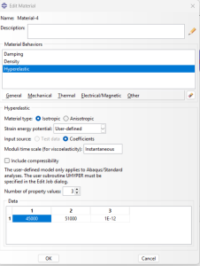
Hyperelastic material model
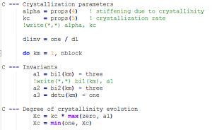
Crystallinity is modeled as an evolving internal variable that depends on the deformation state of the material, increasing only under tensile and shear loading conditions. Its value is constrained within the physical bounds of 0 ≤ ���� ≤ 1, ensuring realistic representation throughout the simulation. As crystallinity increases, the material exhibits progressive stiffening, capturing the strain-induced solidification behavior typical of polymers during processing. To reflect this effect within the constitutive model, both Mooney–Rivlin coefficients are scaled as functions of the evolving crystallinity, enabling the material response to adapt dynamically with deformation.
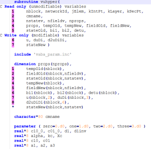 VUHYPER interface
Crystallinity evolution with stretch
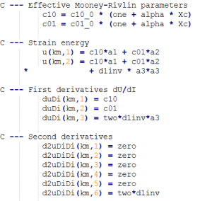
Dependency of hyperelastic parameters on crystallinity
The simulation is carried out using the Dynamic Explicit procedure in Abaqus, which is well suited for problems involving large deformations and severe geometric nonlinearity, as encountered in blow molding. To improve computational efficiency, mass scaling is applied to the entire model with a target time increment of 5 × 10⁻⁶s, effectively increasing the stable time step and reducing CPU time. Although blow molding is inherently a quasi-static process, its highly nonlinear nature makes the explicit approach advantageous. With controlled mass scaling, the method efficiently captures the forming behavior while maintaining a reasonable balance between accuracy and computational cost.
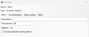
Explicit dynamic step definition
In the blow molding simulation, two key interactions are defined within Abaqus to accurately capture the physics of the process. The first interaction involves defining the contact behavior between the expanding preform and the rigid mold (blow mold cavity). As shown in the image, a contact property named IntProp-2 is created under the Normal Behavior category, where the pressure-overclosure relationship is set to “Hard” Contact with the constraint enforcement method left as Default, and the option to Allow separation after contact is enabled. This ensures that when the preform inflates and comes into contact with the mold walls, it does not penetrate through the rigid surface while still being able to separate if needed. The second interaction defines the Pneumatic Fluid Cavity, which simulates the air pressure driving the blow molding process. interaction is essential as it replicates the internal air pressure that inflates the preform outward against the mold, forming the desired shape during the blow molding process.
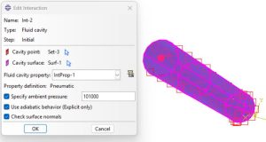
Pneumatic fluid cavity
Results and discussion
The expansion of prefoam at different time steps can be seen in figures below. The left side shows procedure without crystallinity and right side shows the process in which crystallinity is taken into consideration.
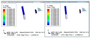
t=0.02 s
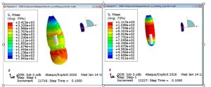
t=0.1 s
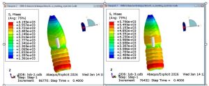
t=0.4 s
The irregular stress regions are visible where crystallinity is not taken into consideration. Now lets take a look at the uniform shell thickness.
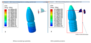
Shell thickness distribution
It can be observed that the shell thickness is more uniform when crystallinity evolution is incorporated. It can be inferred from simulation that, crystallization introduces strain-dependent hardening that suppresses localized thinning. Redistributes deformation to softer regions and naturally leads to a more uniform shell thickness.
The usage of VUHYPER and many more user subroutines in ABAQUS CAE makes it highly customizable and powerful FEA simulation software, which can handle any kind of non-linear structural scenarios.
We Urge You To Call Us For Any Doubts & Clarifications That You May Have. We Are Eager to Talk To You
Call Us: +91 7406663589
 (No Ratings Yet)
#365/8, Ground Floor, "Hasmitha Avenue", 16th Main, 4th T Block East, Jayanagar, 4th T Block East, Pattabhirama Nagar, Jayanagar, Bengaluru, Karnataka 560041
Rated 4.7/5 with a total of 62 reviews
#1120, 11th Floor, Solitaire business Hub - Baner, Balewadi High Street, Baner, Pune-411045
Rated 4.7/5 with a total of 17 reviews
801, 8th Floor, LODHA Supremus, I-Think Techno Campus,Kanjurmarg EAST - MUMBAI, MH, India – 400042.
Rated 5/5 with a total of 51 reviews
501, 5th Floor, Connekt Coworking Space, Gala Argos, Netaji Rd, Ellisbridge, Ahmedabad, Gujarat 380006
Rated 4.1/5 with a total of 7 reviews
Best Engineering Aids & Consultancies Pvt. Ltd. No 306, Karunaa Conclave, 3rd Floor, AD Block, Shanthi Colony, Anna Nagar, Chennai - 600040
Rated 4.6/5 with a total of 16 reviews
Flat no F1, first floor, Nakhate corner, Eknath rang mandir road,New Usmanpura, Aurangabad, 431005.
A-101, 1st Floor, The Hub Complex, opp. Shete Hospital, Mahatma Nagar, Parijat Nagar, Nashik, Maharashtra 422005.
Best Engineering Aids & Consultancies Pvt Ltd (BEACON) Wellwork Workspaces, L1 - 1017A,B, Lower Ground Floor,Vasavi MPM Grand, Ameerpet, Hyderabad, Telangana 500073
2nd floor, Mokha Tower, Plot No.169, Mankapur Ring Rd, Trimurti Nagar, Nagpur, Maharashtra 440022