


In this lesson we are going to learn structural analysis of Lug Support by using 3DEXPERIENCE Structural Designer Role. We will open part in SOLIDWORKS and cleanup the geometry in SOLIDWORKS, we can save the part in 3DEXPERIENCE from SOLIDWORKS itself, we can also open the Structural Designer role from SOLIDWORKS CAD, all we need is to add in 3DEXPERIENCE in SOLIDWORKS CAD.
Open and save to 3DEXPERIENCE stand.
Open the SOLIDWORKS stand part that has not been previously uploaded or saved to the 3DEXPERIENCE platform. Use the Split Line Feature in the Simulation.
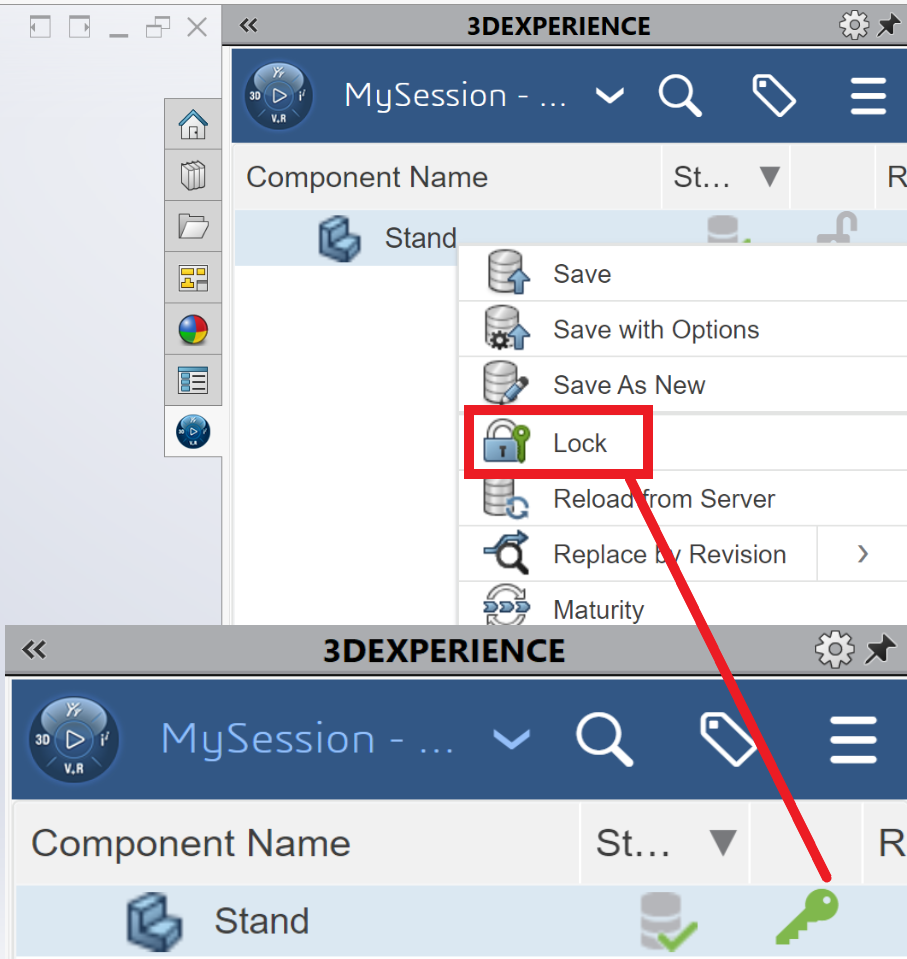
The my session panel displays the component Name, status (Display an icon that represents the status of a given revision ,saved or not saved to the platform), Locked Status is last revision (yes/no), Maturity State (lifecycle state of the Family ,e.g. private ,In work, Frozen, Released, Obsolete), Description, File Name (Display the PLM external ID of the object for reference objects and the PLM external ID of the connection for instance) and Type (physical Product or Drawing)
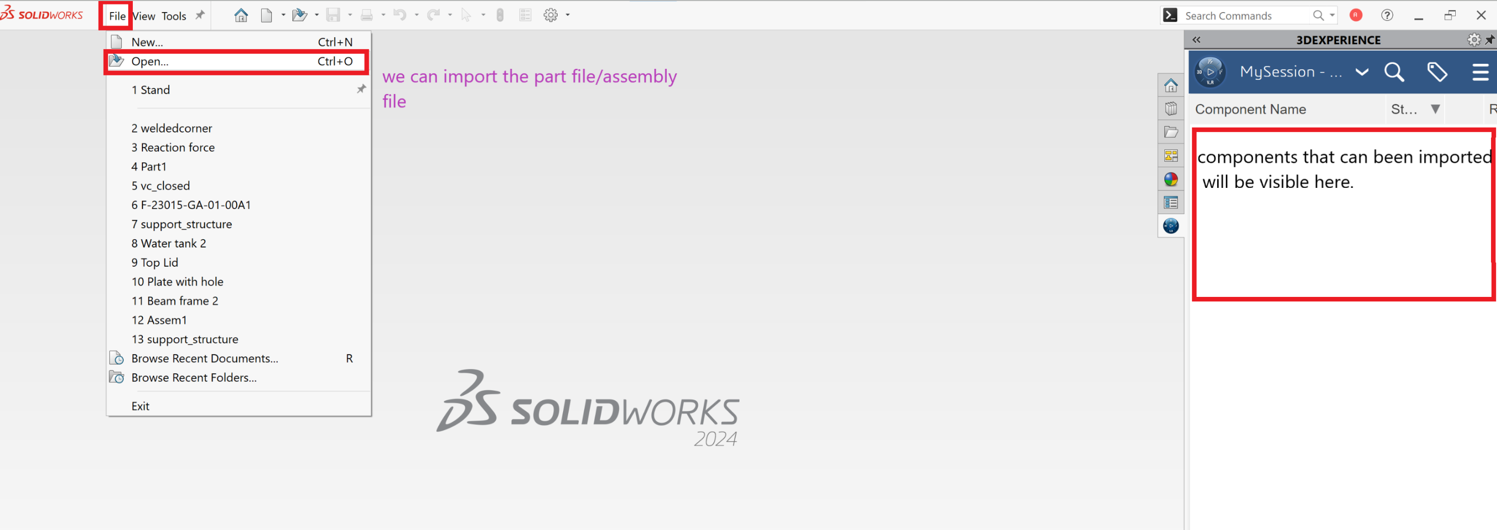
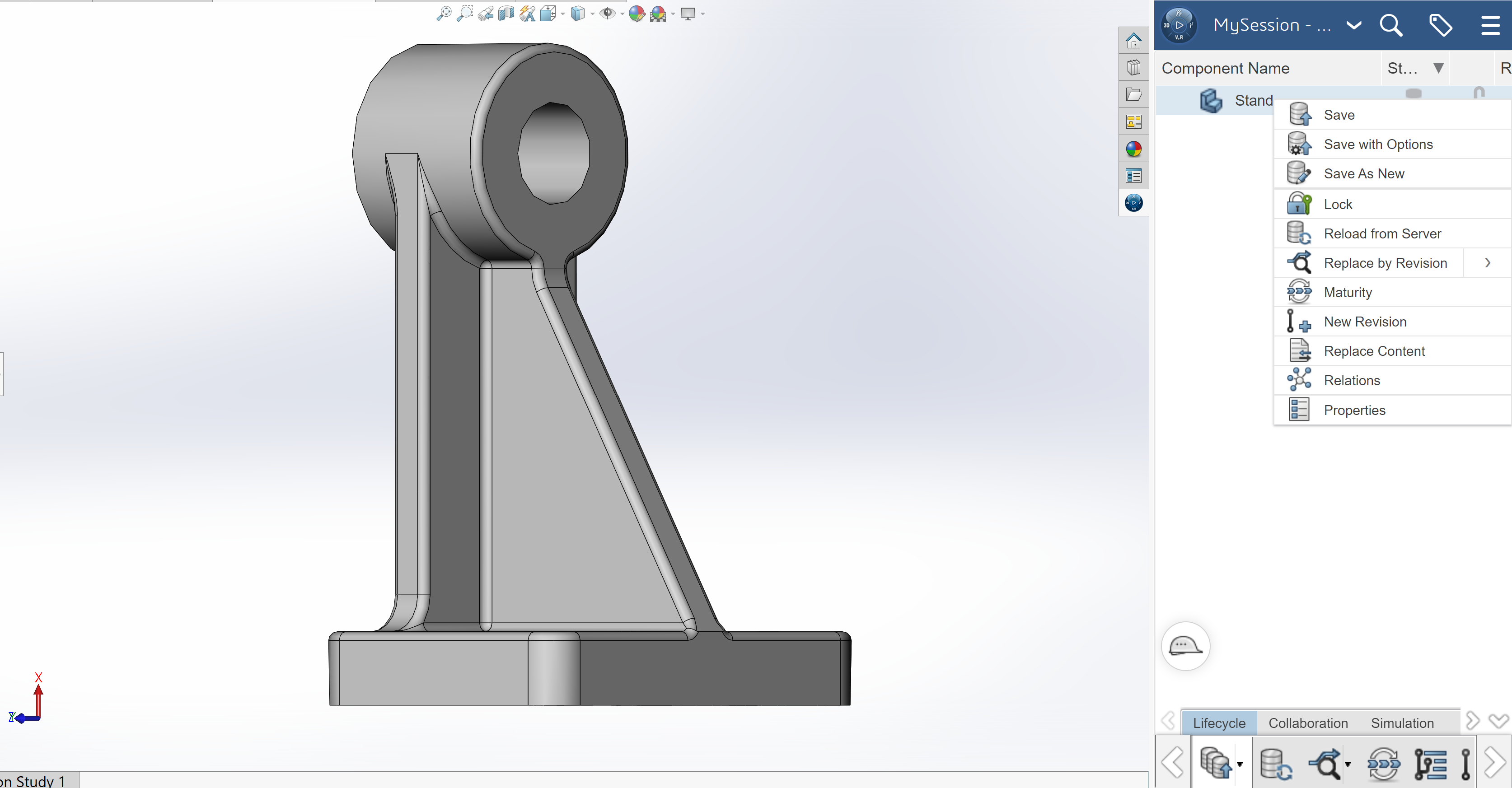
Once we import the part file /assembly file the part will be visible in the graphics window
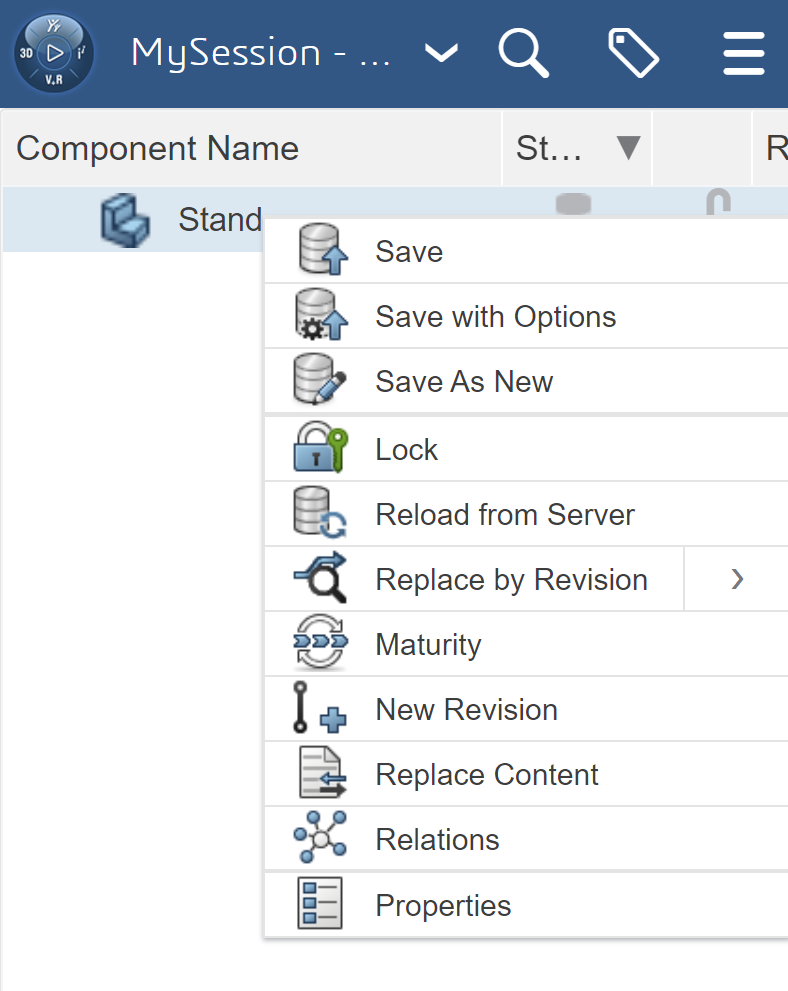
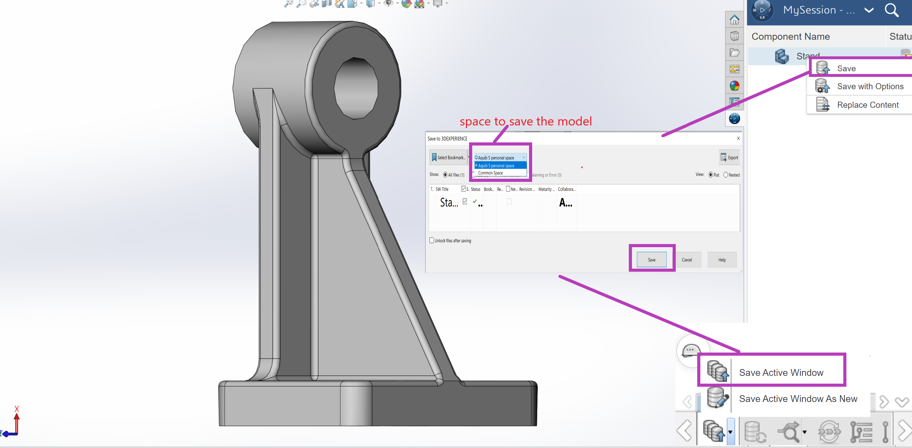
In my session window the same part can be saved on 3DEXPERIENCE ,you have to click on save option to save the model in 3DEXPERIENCE.
Where to save the model in 3DEXPERIENCE? Do we need to create a space or do we have space available in 3DEXPERIENCE?
Answer is Yes you can create a space and also there is common space that can use.
Once the model is succesfully saved in 3DEXPERIENCE you will see green tick in save option as shown in below snap.
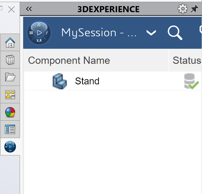
View the Status column in the updated My Session panel. The Status icon displays a green check mark. This means that the current file on your SOLIDWORKS desktop is updated and saved to the platform. The default Revision is A. The Maturity State is In Work. This is the default Lifecycle state after you saved the model to the 3DEXPERIENCE platform.
Linear structural validation App
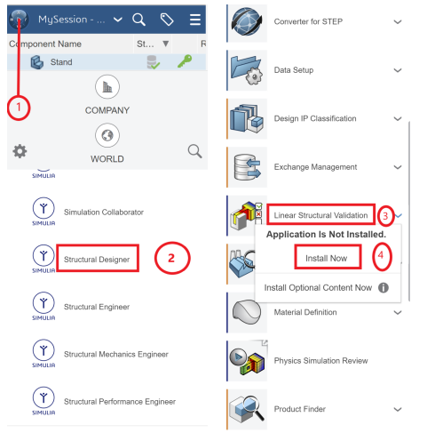
Click the center of the Compass. Use the Linear Structural Validation App. Think of this App as the SOLIDWORKS Simulation Add-in inside of SOLIDWORKS. Most of the 3DEXPERIENCE Apps run in your web browser. 3DEXPERIENCE Simulation Apps perform a small installation on your windows machine. Both types of Apps are linked to your PLM data on the platform. The Linear Structural Validation App provides the ability to Run Linear Structural, Buckling, Frequency, and Thermal Simulation studies.
To open the structural Designer role
Once installation of linear structural validations app is done try to click it again to open the structural validation app
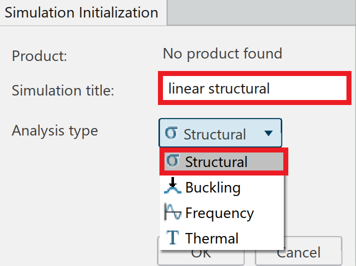
Once you click on linear structural validation app a new window will open in which you will be able to select the type of analysis as shown in below image.
In the simulation title you can give the name of the analysis (e.g Linear structural)
In Analysis type you will be able to select the type of analysis that has to be performed on structural designer role.
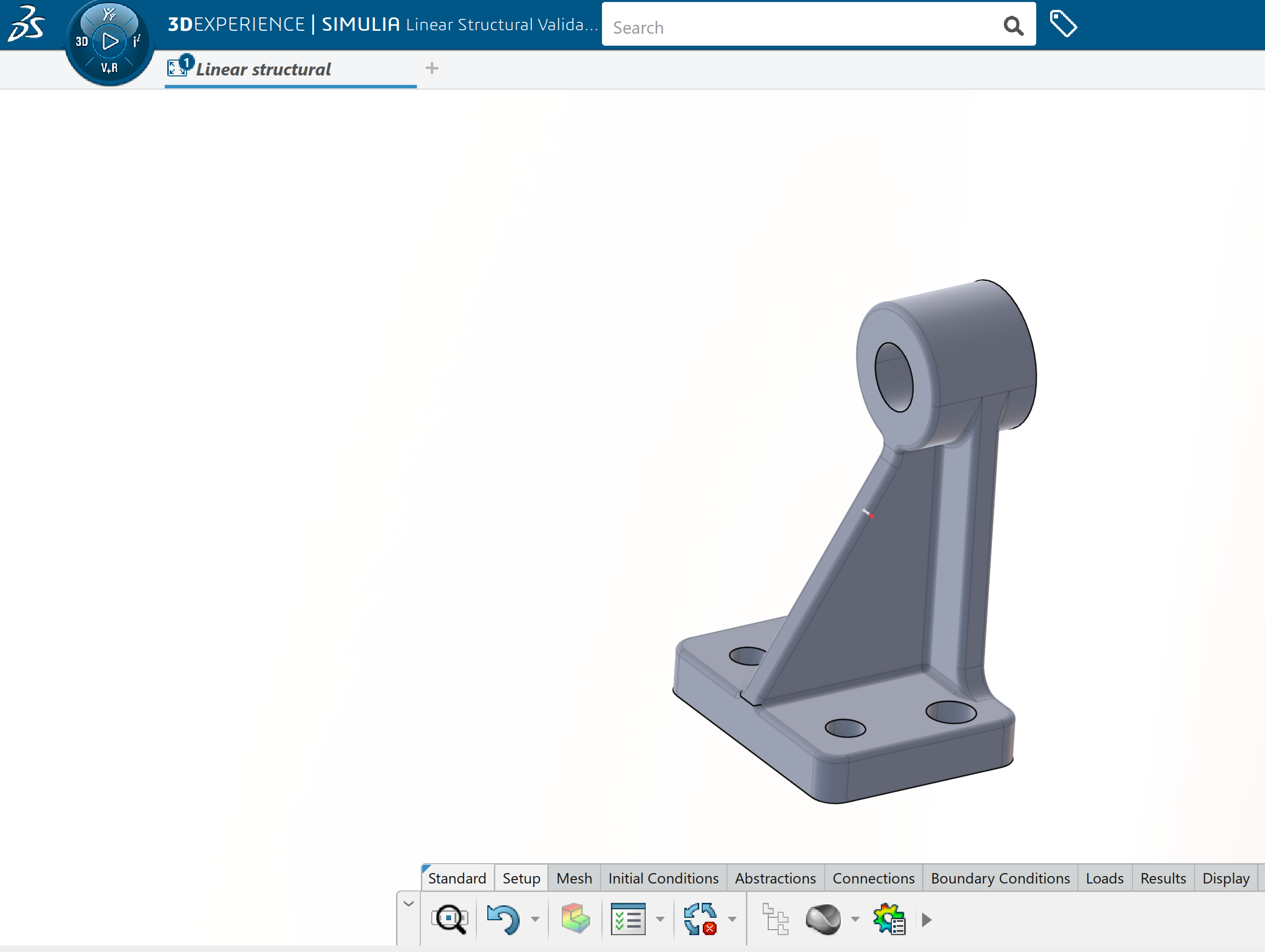
Now the component has been imported successfully into the structural designer role .As we have given the simulation title before(linear structural), the same has been reflected in tab below , we can also change the name by going to the simulation property.
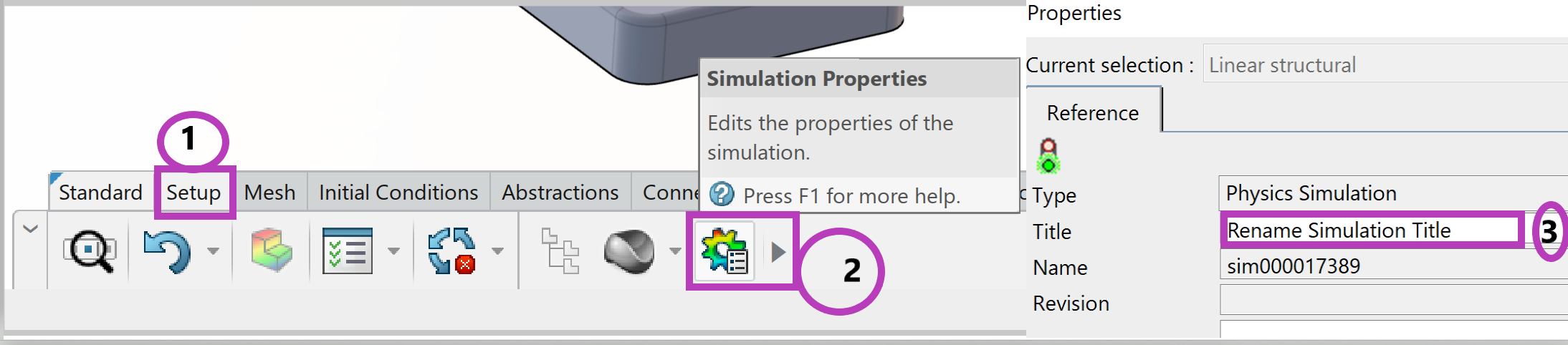
To change the name inside the linear structural validation app
Mesh Generation
Apply a Global mesh. Use the default element type (Tetrahedron second-order elements). Note: Mesh refinement is especially important in regions of high stress concentrations regions like sharp corners fillets. Typically, a smaller element size gives more accurate results, and at the same time computation time will be high.
Global mesh
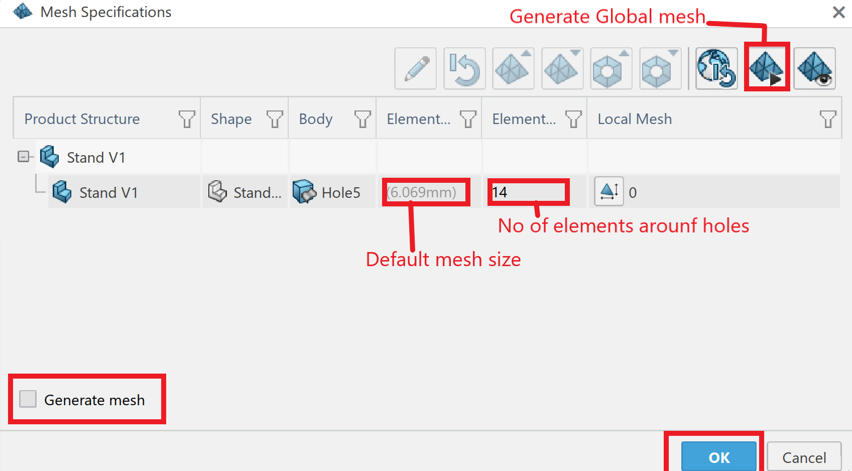
Click on the mesh module and select mesh specification a window (mesh specification) will popup where you will be able to increase or decrease global mesh size

By default the mesh size of this component has been taken automatic and global size /default size was found 6.09mm and no of elements around holes 14.
Now if you click on the generate mesh so that you can generate mesh with global element size.
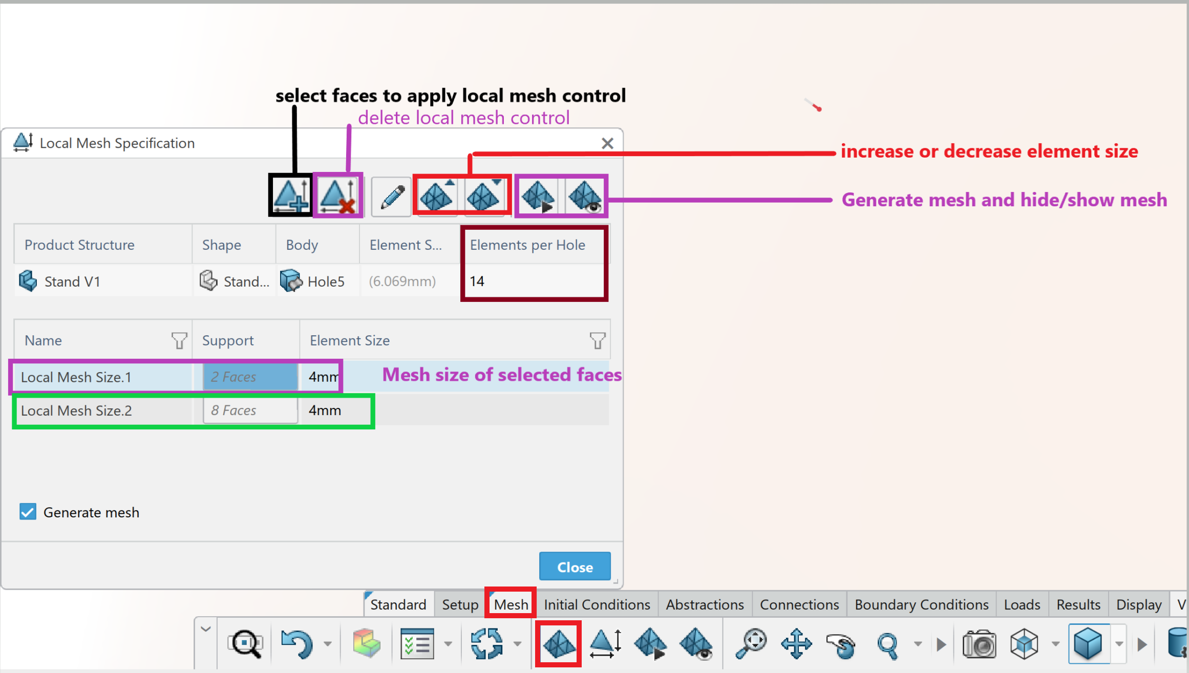
Local mesh control
You can use the local mesh control to refine the mesh in stress concentration regions thus the results will be more accurate in stress concentration region.
You can select the faces /body to apply local mesh control
You can increase or decrease the element size.
You can control the number of elements around hole.
You can use 1st and 2nd order tetrahedron elements.
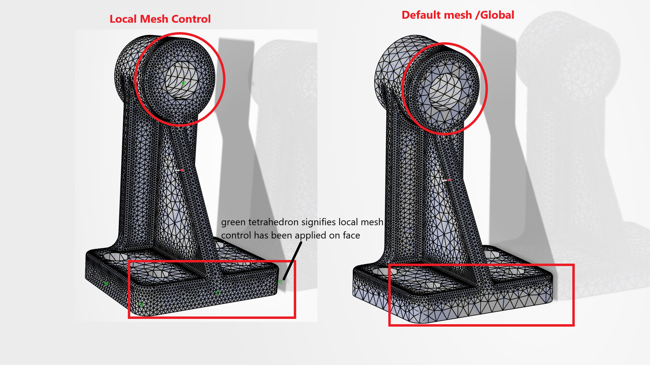
Before and after application of local mesh control
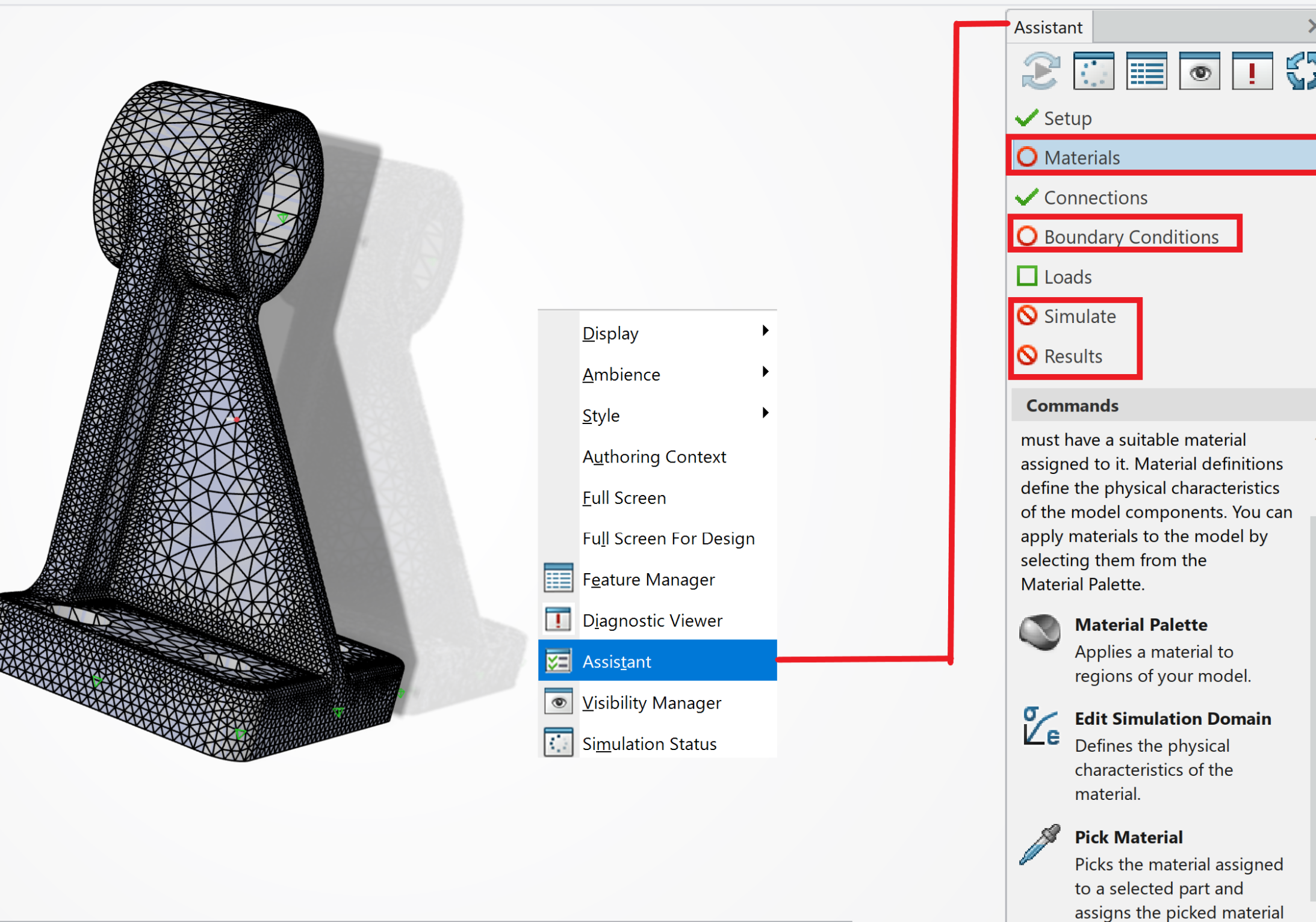
Assistance
Right-click in the Graphics area.
The Assistant will be displayed. Assistance will guide us throughout the simulation process from preprocessing to post processing. If by chance we forget to apply material properties, this will highlight the material section with red circle (o) as shown in below image.
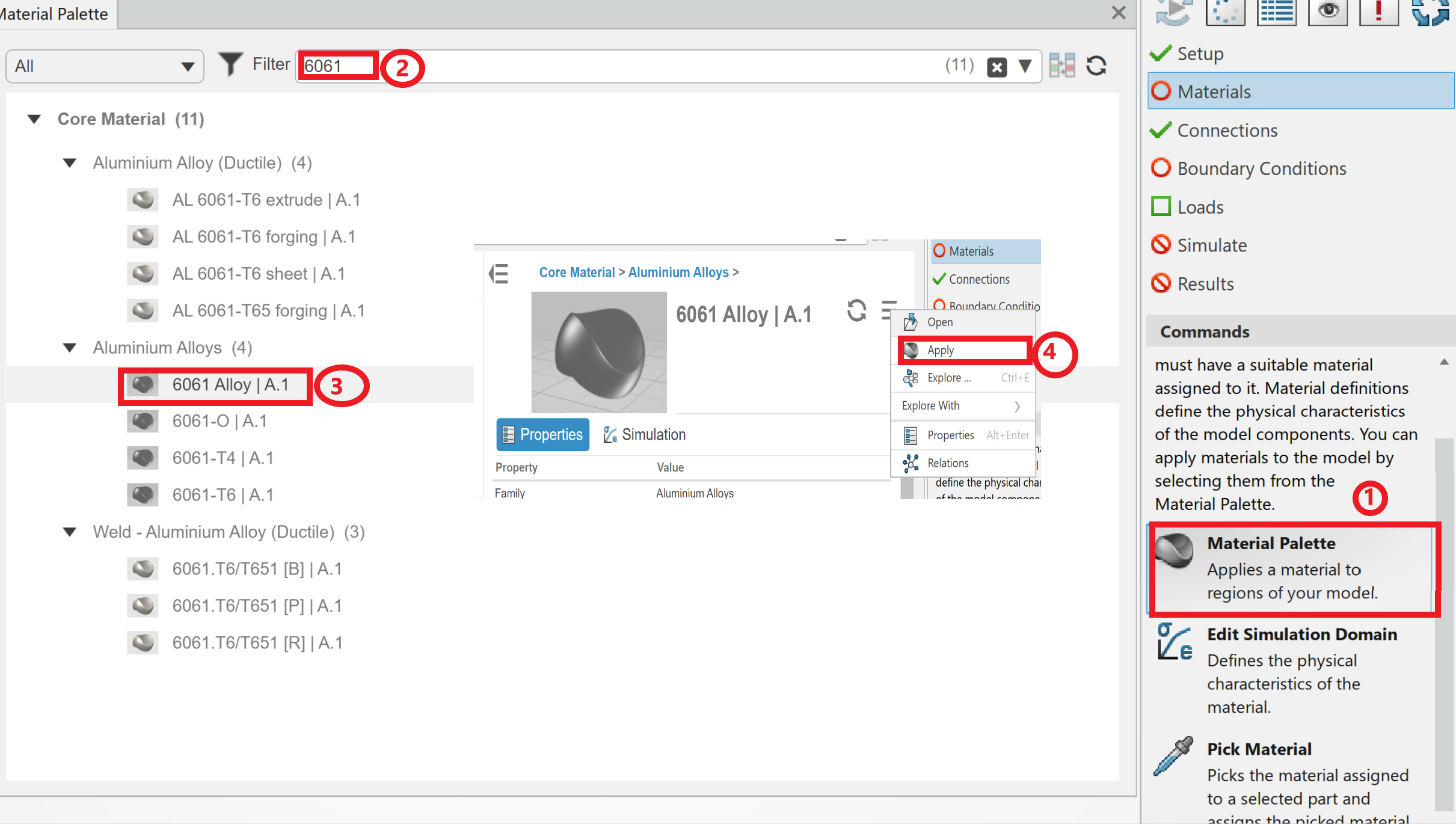
Material application
Since the Assistance has guided us that material has not been assigned yet ,lets apply the material by going to the Material Palette.
You can directly click on material palette from the Assistance window.
Use the filter option to find out the material Aluminum Alloy 6061.
Click on apply-to-apply material to the part.
Boundary conditions
Address Boundary Conditions. Constraints are used to restrict the motion of certain surfaces in the model when load is applied . In a linear Static stress simulation, one or more constraints are required.
Click Boundary Conditions from the Assistant dialog box.
Drag the slider downward to view clamp that is used to prevent moving and deforming the parts.
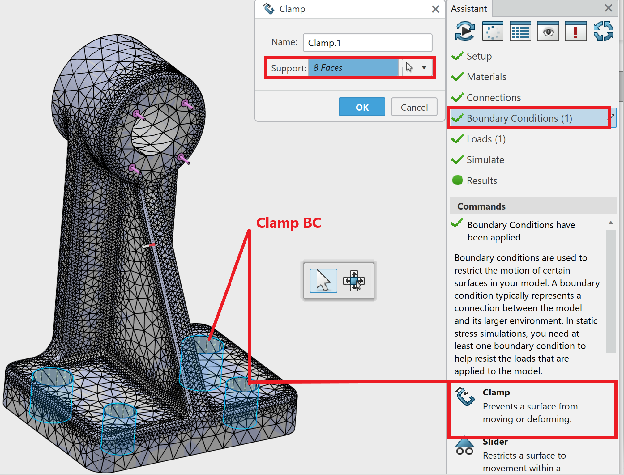
Click clamp BC.
The CLAMP dialog box is displayed.
Select all the faces of cylindrical holes of the support mount as illustrated. 8 Face is displayed in the Support box.
Click the X, Y, Z Translation box. No movement and deformation in the X, Y, Z directions will occur near the cylindrical hole.
Click OK from the clamp dialog box. Boundary Conditions display a green check mark in the Assistant.
Loads
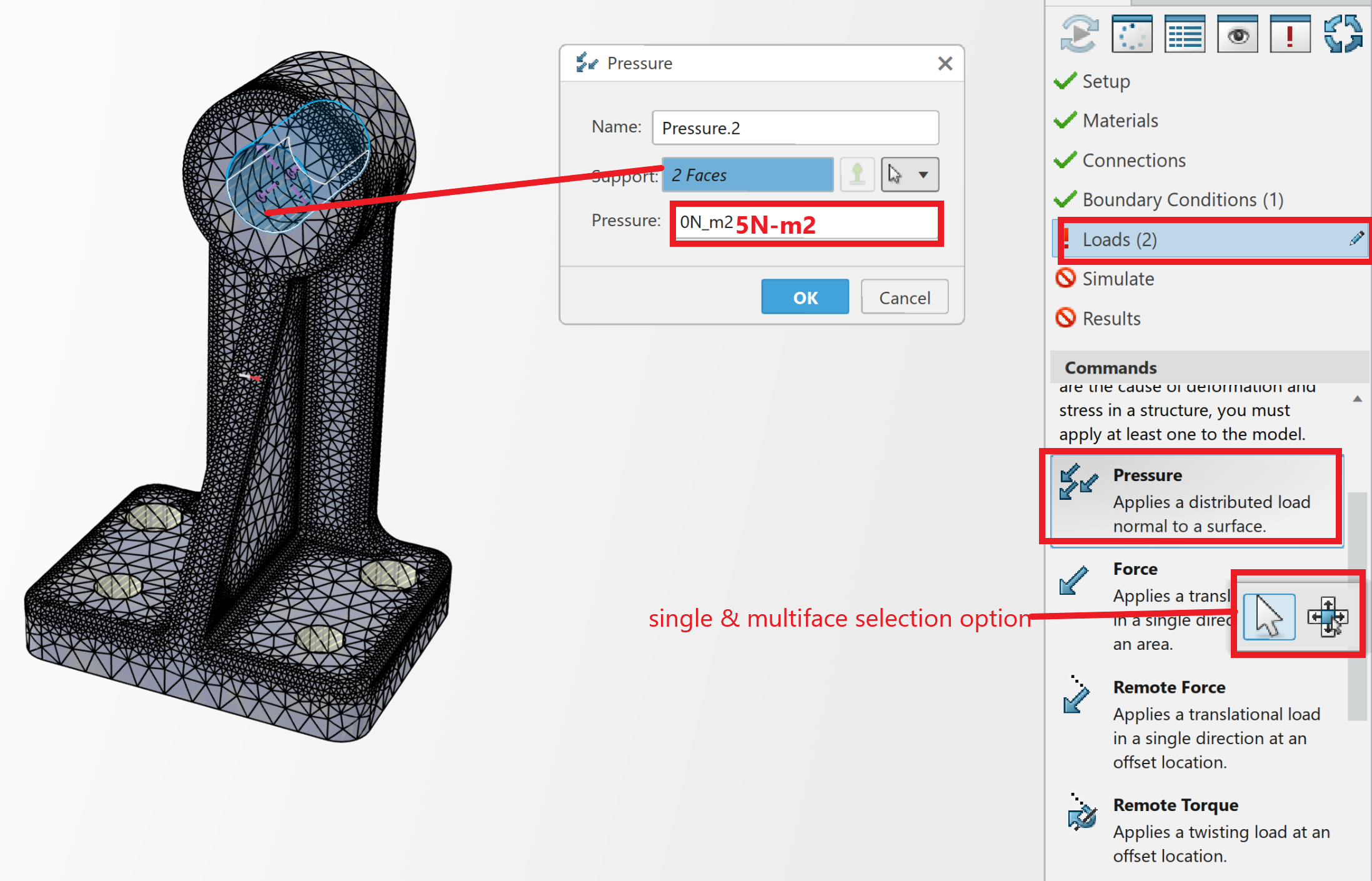
Apply a pressure load in surfaces shown in the below image.
Click Loads from the Assistant dialog box.
Drag the slider downward to view pressure.
Click pressure and apply 5N-m2.
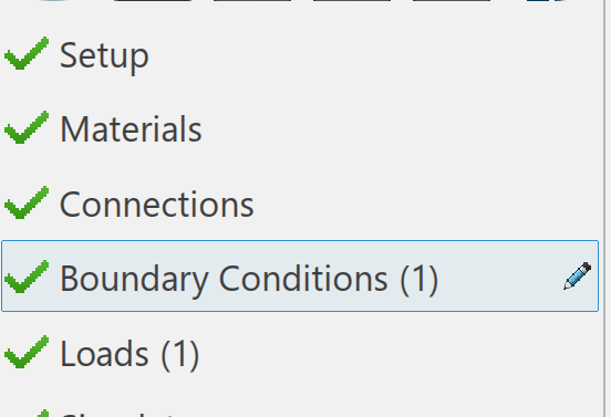
As you can see in the below plot ,all the material ,loading and boundary conditions has been created successfully shown In the assistance dialog box with green tick mark .
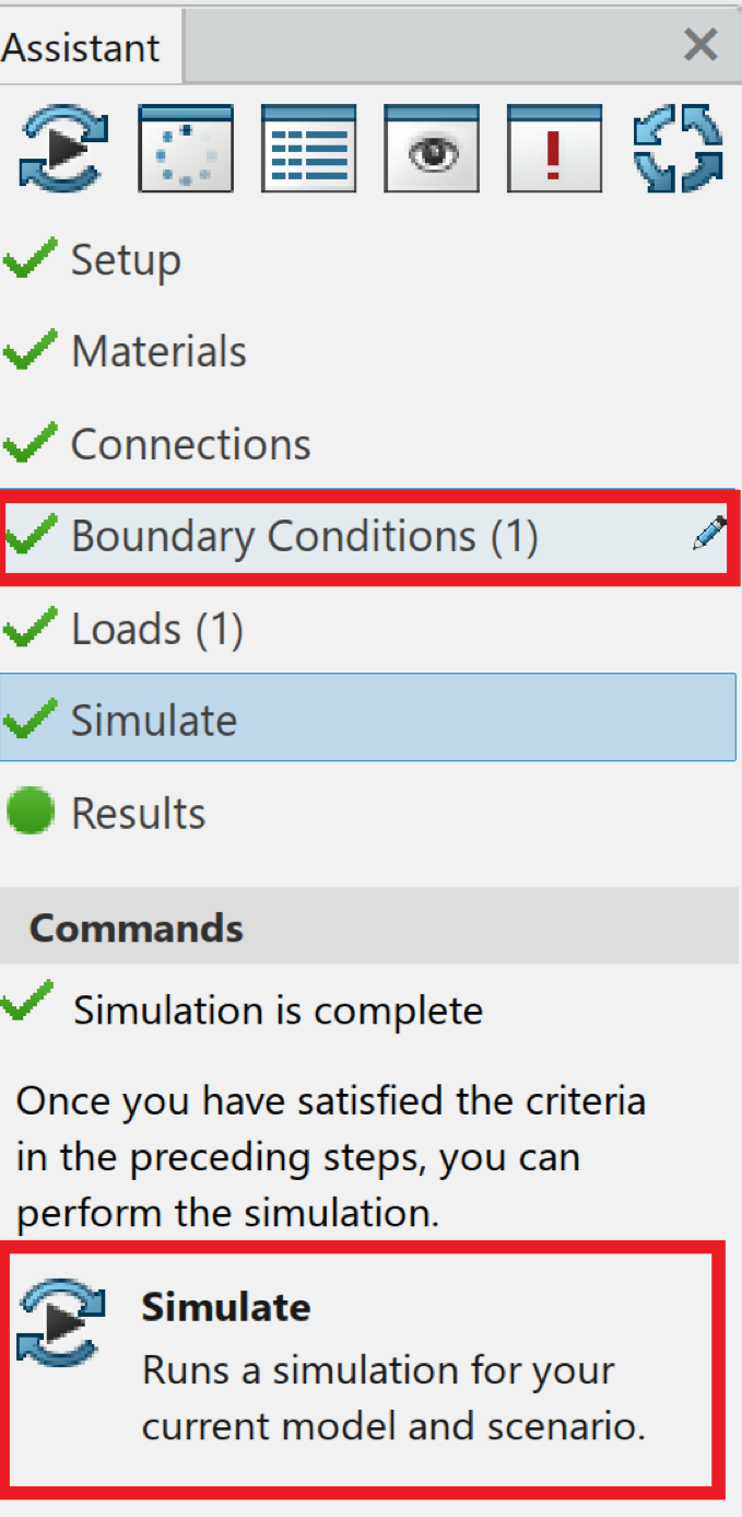
Now we are ready to go and run the analysis .
SIMULATE
In this module we will run the simulation
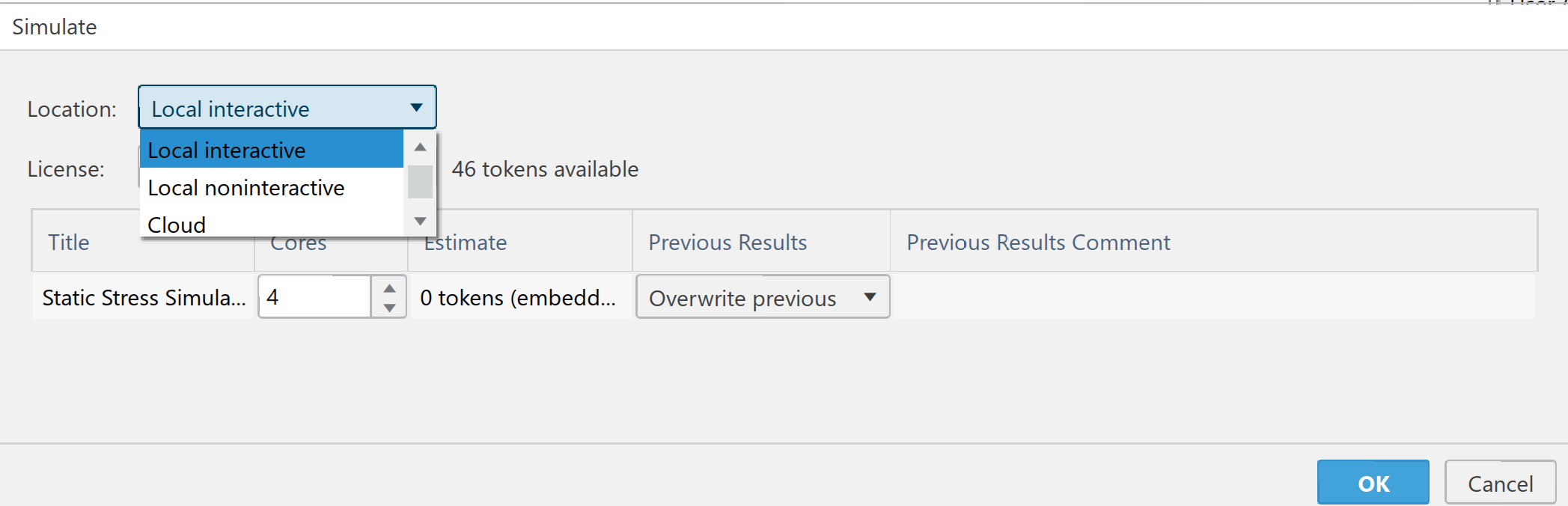
Click on the simulate from the assistance dialog box as shown in below image.
By default, the simulation runs on your local machine using an embedded license. Local interactive is set by default. The Local interactions define interactions between sets of geometric entities of solids, shells, and beams.
You can choose local interactive, local non-interactive & cloud resources.
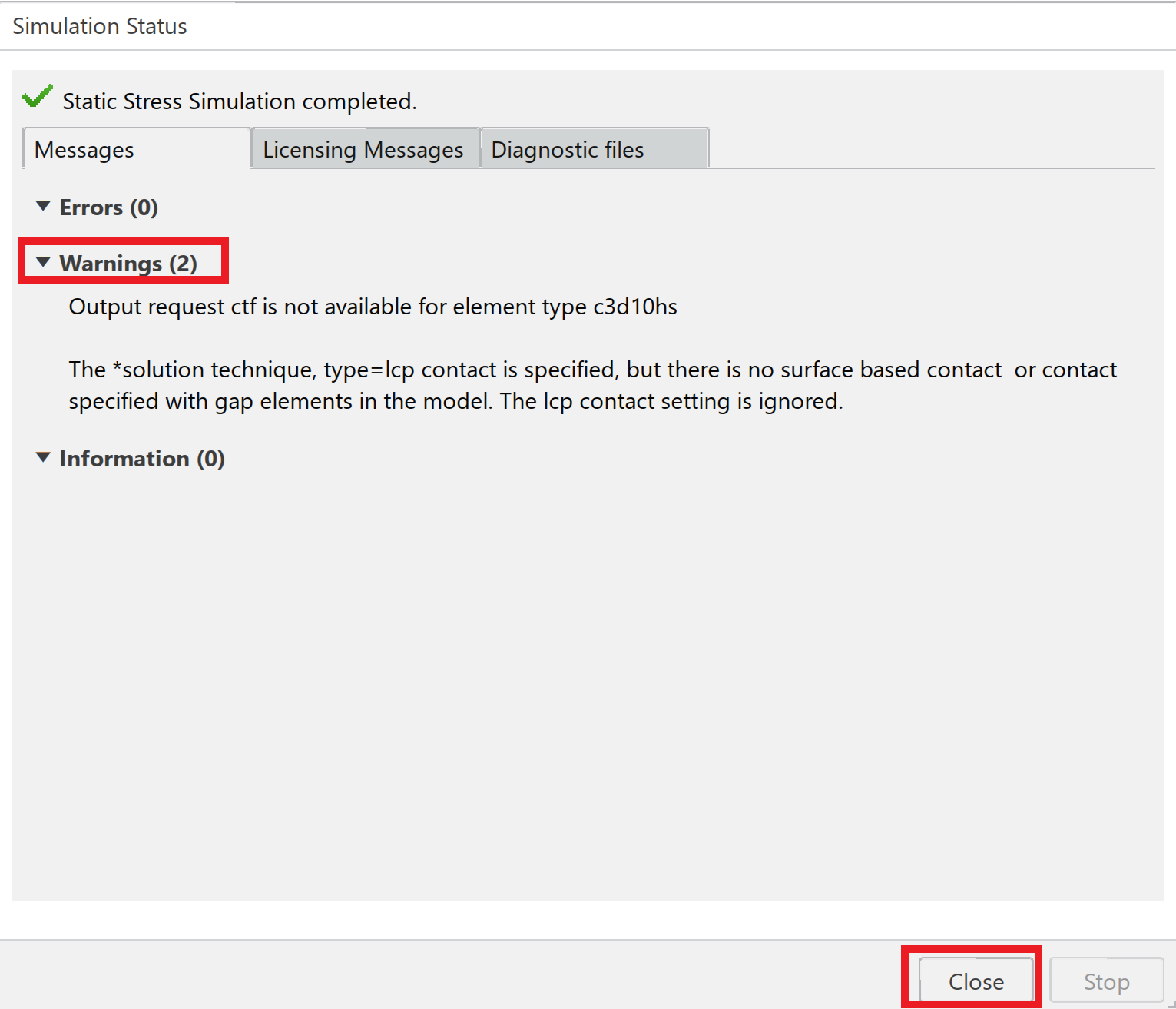
Expand and Read the Warnings
You can close the status window by clicking on close
REVIEW THE RESULTS
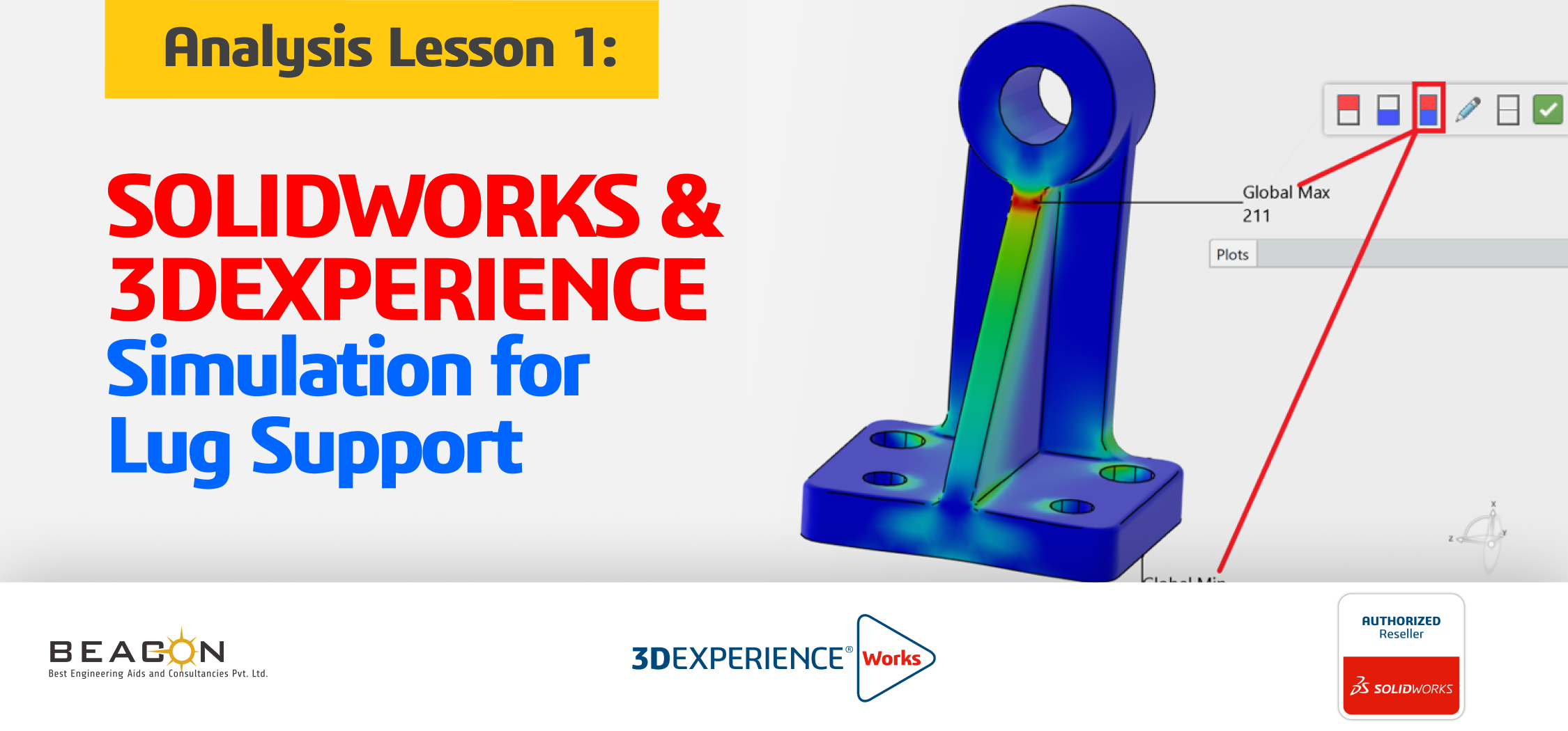
Analyze the simulation results to understand the stress and displacement patterns that develop due to the pressure loading. The Von Mises Stress plot is displayed by default.
In this example, use the results plots for the Von Mises stress, displacement, and factor of safety (FOS). Verify that the Von Mises stresses do not exceed the material’s yield strength. For most metals, the yield strength is defined as the stress point at 0.2% strain offset. For 6061 Alloy this is (5.157 × 10⁷N/m2).
The mouse cursor will act as a probe, and it will be easy to find out the max stress location.
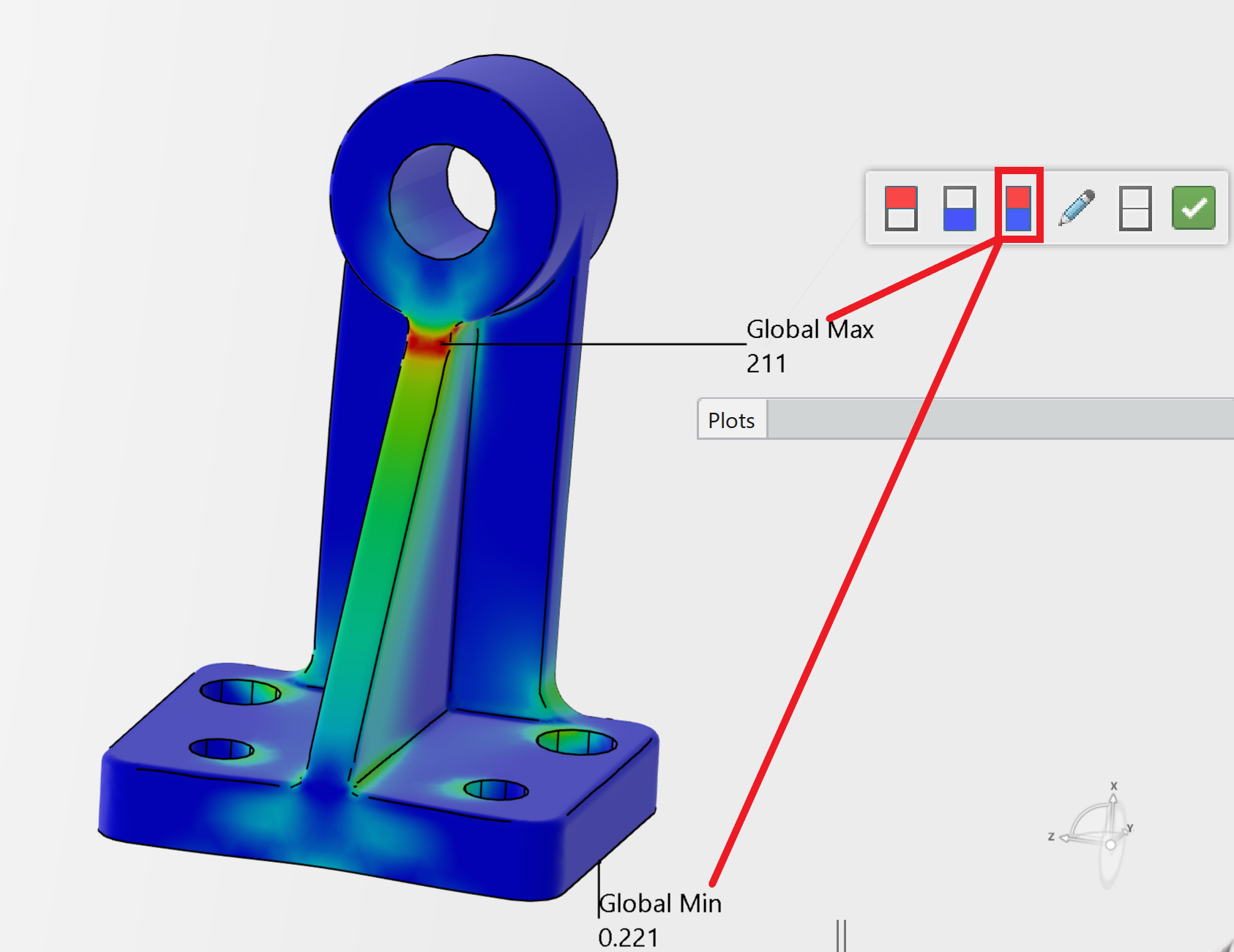
Rotate the component to view the high stress regions.Click a node on the model as illustrated. View the Von Mises Stress at that point. A Pop-up menu is displayed. Note: To deselect the displayed point, click in the Graphics area.
The maximum stress occurs at the fillet of the stand as illustrated. The maximum Von Mises stress (211 N/m2) is below the material’s yield strength of (5.157 × 10⁷N/m2).
Global Max and minimum von Mises Stress Plot
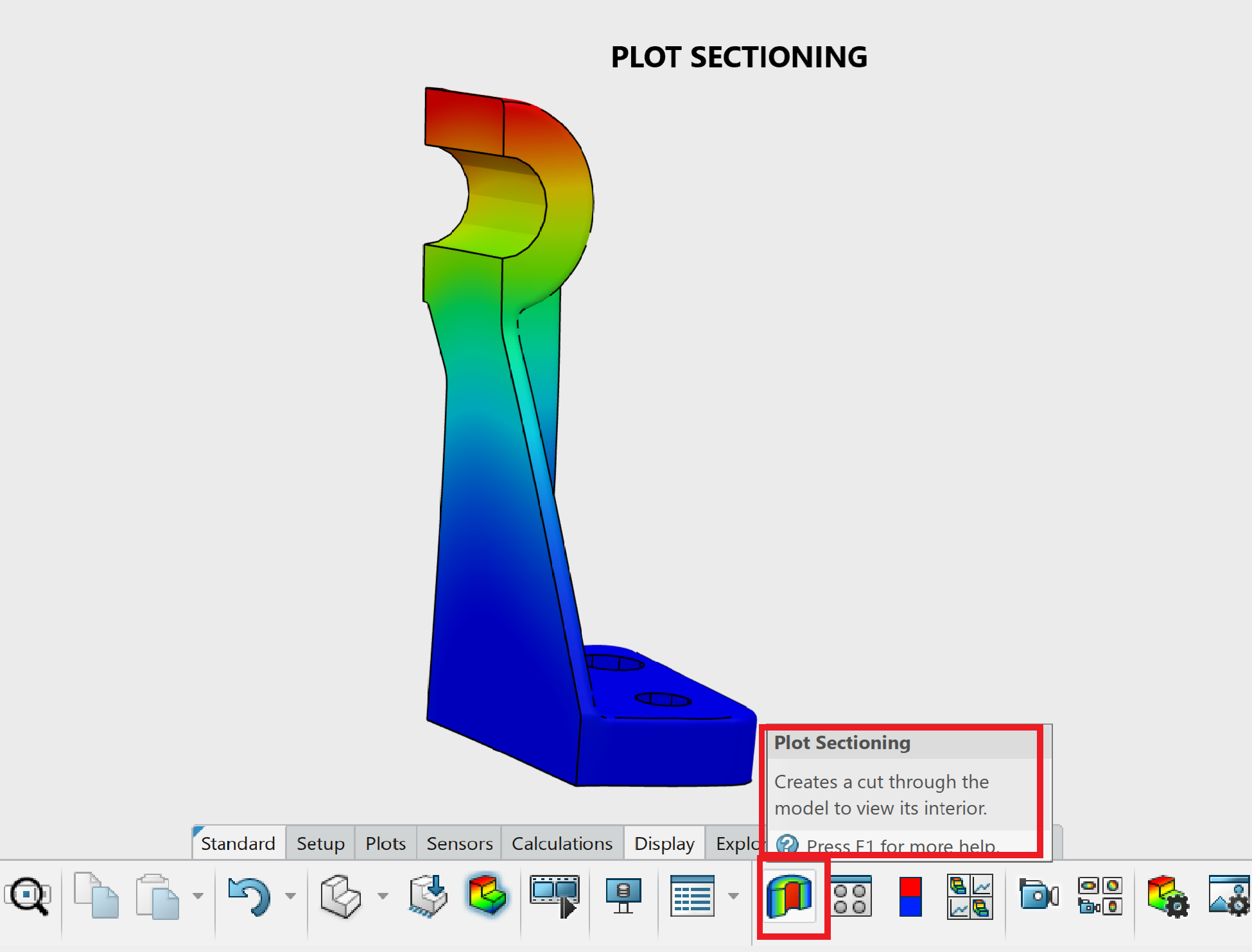
Plot sectioning
Section clipping can be used to view the results along the section of a component.
This can be turned on by using plot section as shown in snap below.
Displacement contour plot.
Create a Displacement contour plot.
Note: In SOLIDWORKS Simulation the URES Resultant Displacement and the Displacement in 3DEXPERIENCE Simulation represents the same displacement components. Displacement Component x, y and z in 3DEXPERIENCE Simulation represents the same displacement components as UX, UY and UZ in SOLIDWORKS Simulation.

Maximum displacement is coming on top of stand and is found 7.25e-5mm.
Factor of Safety (FOS)
Review the Factor of Safety (FOS) contour plot to identify the most critical regions of the part.
The factor of safety plot displays how close a material is to yielding. The FOS is calculated by dividing the material’s Proof (Yield) Strength by the Allowable stress.
Create a Factor of Safety (FOS) contour plot.
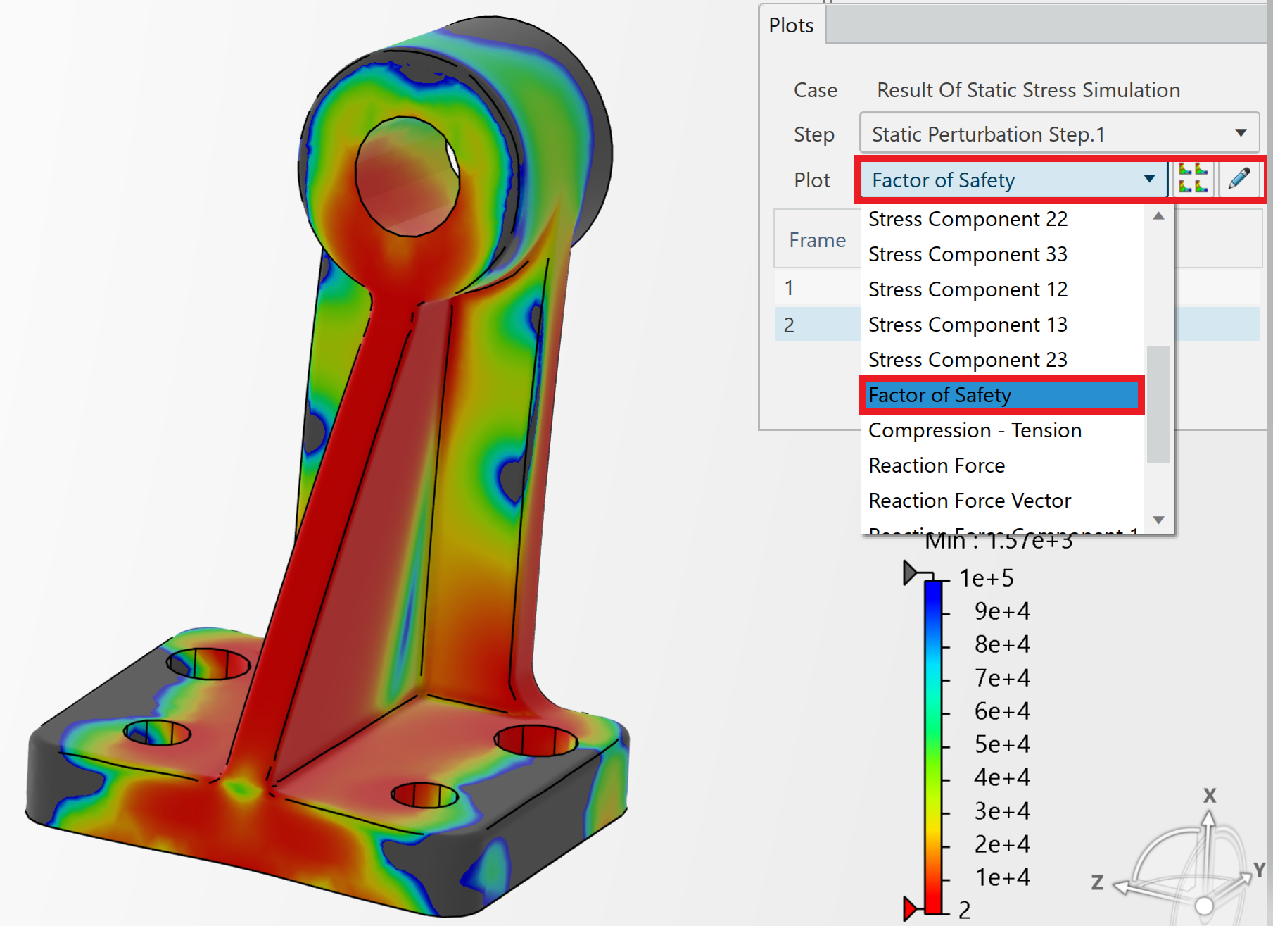
The FOS plot has a maximum limit of 1e+5 by default (region in grey). Regions of the model with a FOS larger than 1e+5 are shown in gray..
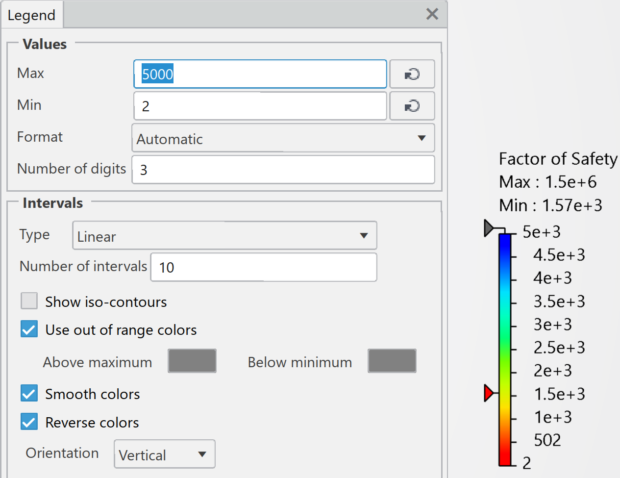
Note: To modify the values of a contour plot, double-click the plot legend, and enter new values.
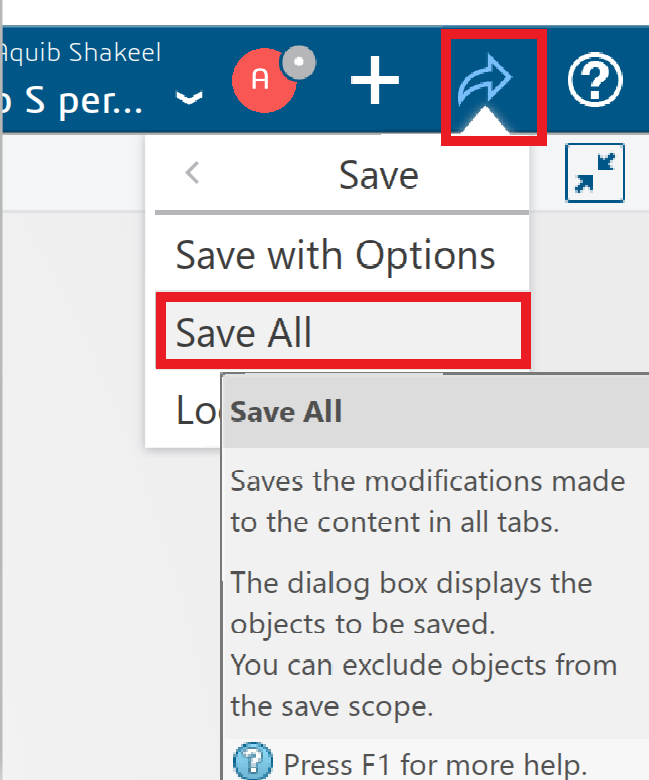
Save the model and Simulation Study results.
Click the Share icon as illustrated.
Click Save. By default, the model and simulation study data are saved to your Collaborative space on the platform. For Simulation study data, there are two locations, either on your local machine or on the platform. By default, the Simulation study data is stored to Collaborative space.
We Urge You To Call Us For Any Doubts & Clarifications That You May Have. We Are Eager to Talk To You
Call Us: +91 7406663589
 (No Ratings Yet)
#365/8, Ground Floor, "Hasmitha Avenue", 16th Main, 4th T Block East, Jayanagar, 4th T Block East, Pattabhirama Nagar, Jayanagar, Bengaluru, Karnataka 560041
Rated 4.7/5 with a total of 62 reviews
"CARAX" Building 4th Floor, 105/1/1/4, Next to Radha Hotel, Pune-Mumbai Xpress Way,Baner,Pune 411045
Rated 4.7/5 with a total of 17 reviews
1002, LODHA Supremus, I-Think Techno Campus,Kanjurmarg EAST - MUMBAI, MH, India – 400042.
Rated 5/5 with a total of 51 reviews
508, Shiti Ratna Complex, Panchwati Cross Road, Ahmedabad-380006
Rated 4.1/5 with a total of 7 reviews
Kanda's Villa, II Floor, AE Block,3362 R, 8th Street, Anna Nagar, Chennai, Tamil Nadu 600040
Rated 4.6/5 with a total of 16 reviews
Flat no F1, first floor, Nakhate corner, Eknath rang mandir road,New Usmanpura, Aurangabad, 431005.
A-101, 1st Floor, The Hub Complex, opp. Shete Hospital, Mahatma Nagar, Parijat Nagar, Nashik, Maharashtra 422005.
Level 7, Octave 3B Salarpuria Sattva Knowledge City, Inorbit Mall Road, Raidurg Village, Hi-tech City, Hyderabad, Telangana - 500081, India
Bienvenue sur ma chaîne YouTube dédiée au monde captivant des jeux vidéo ! Ici, vous trouverez une variété de contenus passionnants allant des stratégies épiques d'”Age of Empires” aux aventures palpitantes de différents jeux.