


Dassault Systems is the proprietor of SOLIDWORKS along with a suite of simulation software applications. This collection includes SOLIDWORKS Simulation, CATIA Analysis, Abaqus, among others, all falling under the SIMULIA umbrella.
This lesson will guide you through the correct process for transferring a SOLIDWORKS part to the 3DEXPERIENCE platform. Once uploaded, you’ll utilize the Fluid Scenario Creation App to conduct flow analysis on globe valve. This application offers comprehensive analysis capabilities for both internal and external fluid flows, ensuring a thorough examination of the system’s performance.
First, open the SOLIDWORKS part that hasn’t been saved to the 3DEXPERIENCE platform. Then, follow these steps:
By following these steps, you’ll successfully upload, simulate the behavior of the globe valve using the 3DEXPERIENCE platform’s Fluid Scenario Creation App.
Problem statement
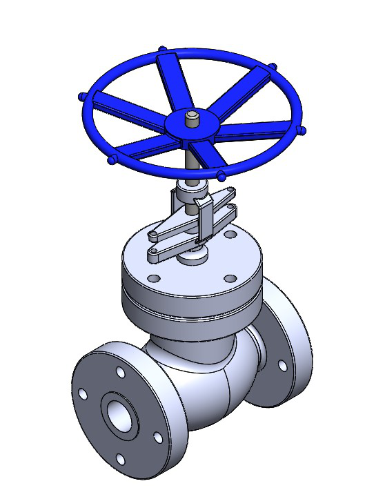
A globe valve is a type of flow control valve commonly used in piping systems to regulate or stop the flow of fluid. It features a spherical body with an internal baffle, creating a Z-shaped passage that offers precise control. The valve’s disc, connected to a stem, moves perpendicular to the flow, allowing for fine-tuned adjustments. Due to its design, the globe valve is known for providing a tight seal when closed, making it suitable for applications requiring high-pressure or high-temperature resistance. Its versatility and durability make it a popular choice in industries such as oil and gas, water treatment, and power generation (a video is shown below for more clarity on application). The flow analysis of globe valve is highly essential since it is used in various industry verticals. The tools which is aided by Computational Fluid Dynamics (CFD) can be utilized for the same simulation. Hence, in this lesson we attempt to simulate the internal flow inside a 2-inch globe valve using 3DEXPERIENCE Fluid Dynamics Engineer.

The isometric view of globe valve is shown in the figure below.
Before we dive in, here’s what you need to know:
This lesson on Flow Simulation is perfect for beginners who want to solve real-world engineering and design problems using simulation. It’s helpful to have a basic grasp of flow, pressure, velocity, and the Computational Fluid Dynamics (CFD) method.
You’ll also need to have the 3DEXPERIENCE Launcher installed.
Download the globe valve model from the following link.
Globe valve
To initiate a SOLIDWORKS session from your desktop, simply double-click the SOLIDWORKS icon.

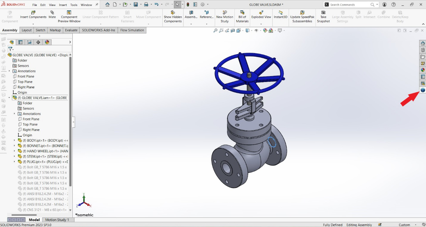
After opening SolidWorks, open the downloaded globe valve model by clicking “File-open-(browse for file)-click open” in the menu bar. Now the model is opened in SolidWorks as shown below. Now go to the 3DEXPERIENCE compass (indicated by red arrow) shown in command manager.
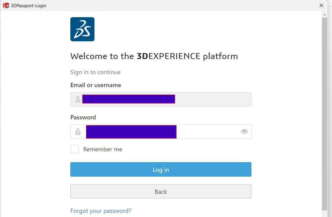
Log into the 3DEXPERIENCE platform using your credentials.
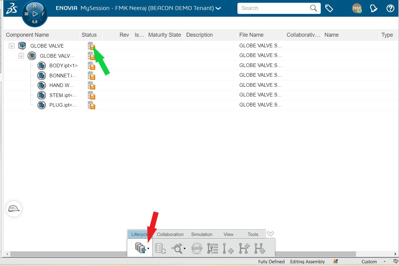
When logged into the platform, you can see an orange save status (green arrow) to the right of the component name. It means that you have not saved your part to the platform. To save the same, please click on save active window (red arrow).
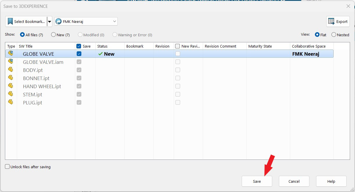
Please click ‘save’ on the following dialogue box.
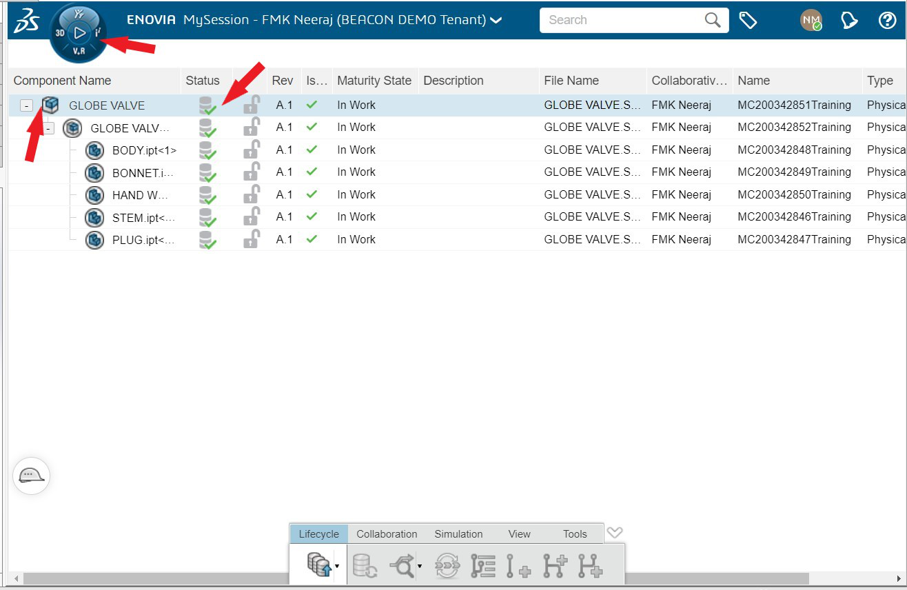
Now it is visible that the model is saved to the platform (green tick near arrow). Now click on the component and click on compass.
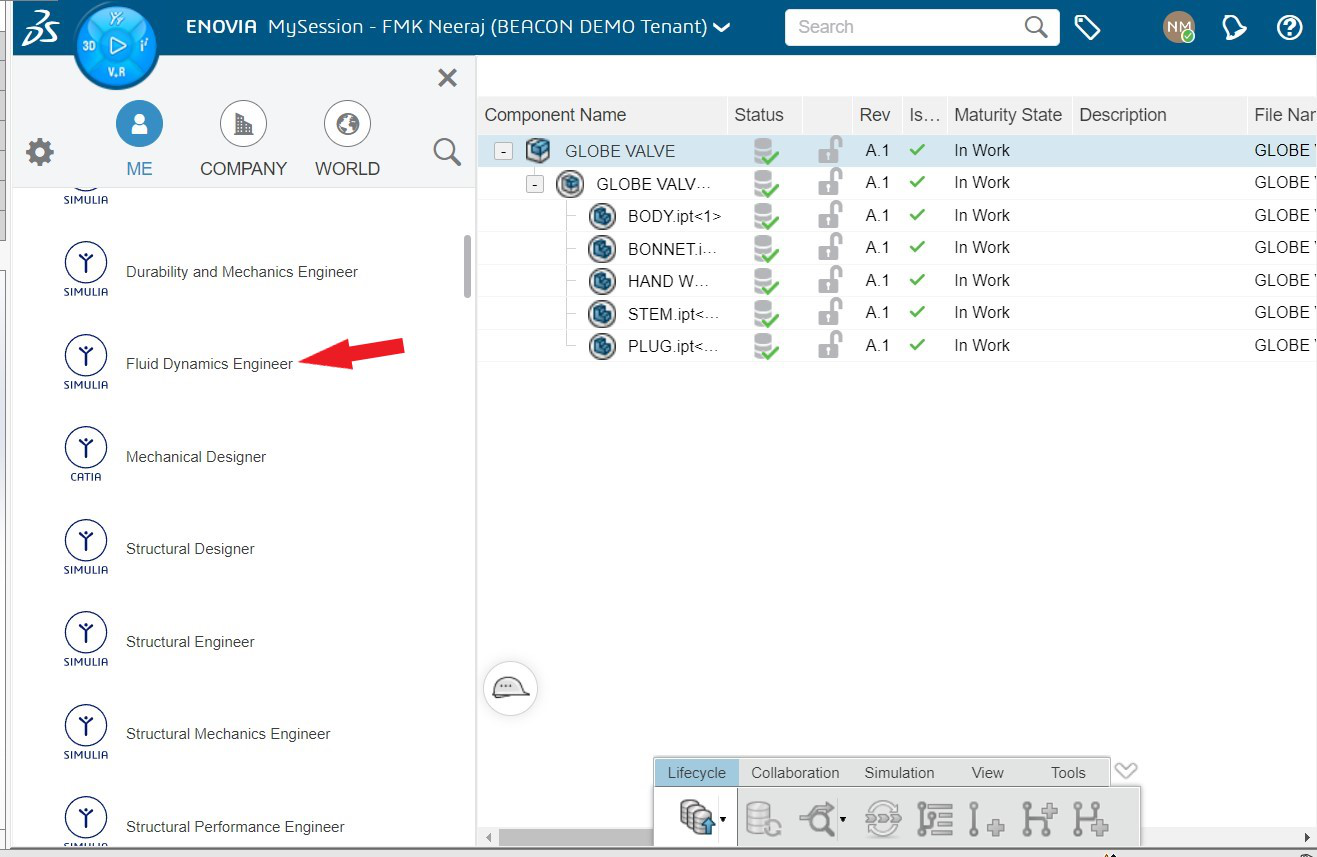
From the compass select the fluid dynamics engineer role.
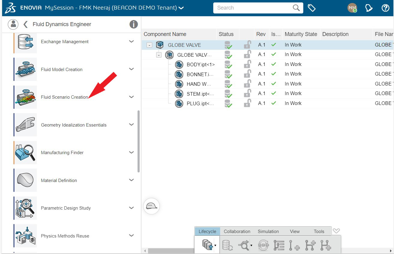
When fluid dynamics engineer role opens, select fluid scenario creation app from the list.
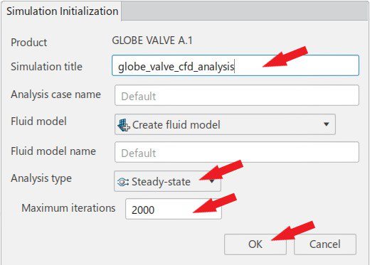
3DEXPERIENCE fluid scenario creation has opened with the globe valve model as shown below. Rename the simulation title as “globe_valve_cfd_analysis”. Keep the analysis type as steady and maximum iterations 2000 by default. Click ‘ok’ then.
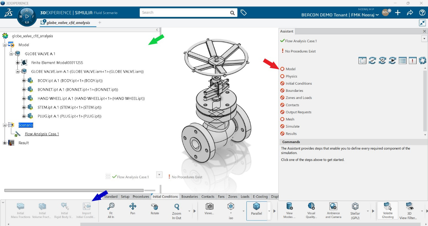
The CFD simulation is created now. The window consists of simulation tree at left side (green arrow), the guided user assistant (red arrow) and the action bar (blue arrow). The advantage of fluid dynamics engineer is the presence of guided user assistant. It shows what are the steps to be defined, and whether any errors are there in any definition of model and scenario. The workflow can also be taken through action bar. However, we are going to pursue the easier way by using the user assistant. Click on model in the user assistant.
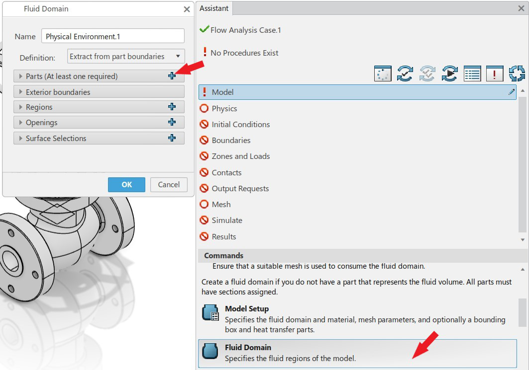
After clicking on model, lot of options such as model setup, fluid domain, fluid section, solid section, VOF, porous, multispecies section are visible at bottom part of assistant. As the first part of preprocessing, we create the fluid domain. Click on fluid domain and then in the dialogue box, click ‘+’ on parts.
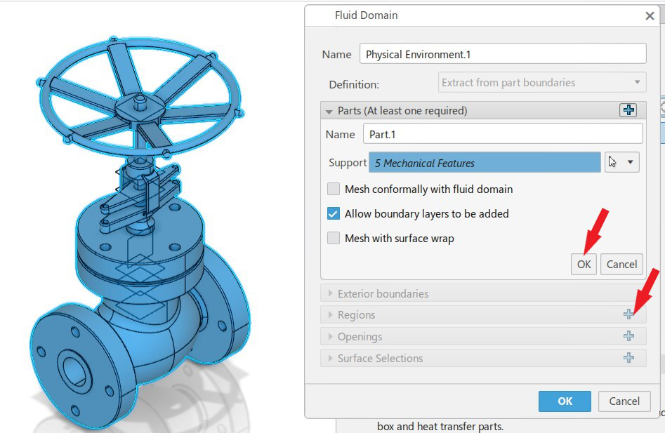
In the part section, select the geometry by either dragging the mouse over it or by just clicking on it. The dragging is useful when more than one part is involved. Make sure that ‘allow boundary layers to be added’ dialogue is checked. Now click ok and then click ‘+’ right to region where we will define the fluid region. Leave the exterior boundaries section unchecked since the flow is internal.
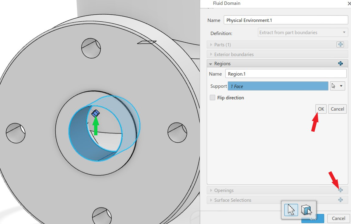
In the regions section, select the internal face at any of the flow opening as support and rectangular glyph will be shown (green arrow). This represents the fluid region. We know that fluid is inside the model. Hence, make sure that glyph is inside the model by checking flip direction. Now click ok in the regions section and then ‘+’ right to openings.
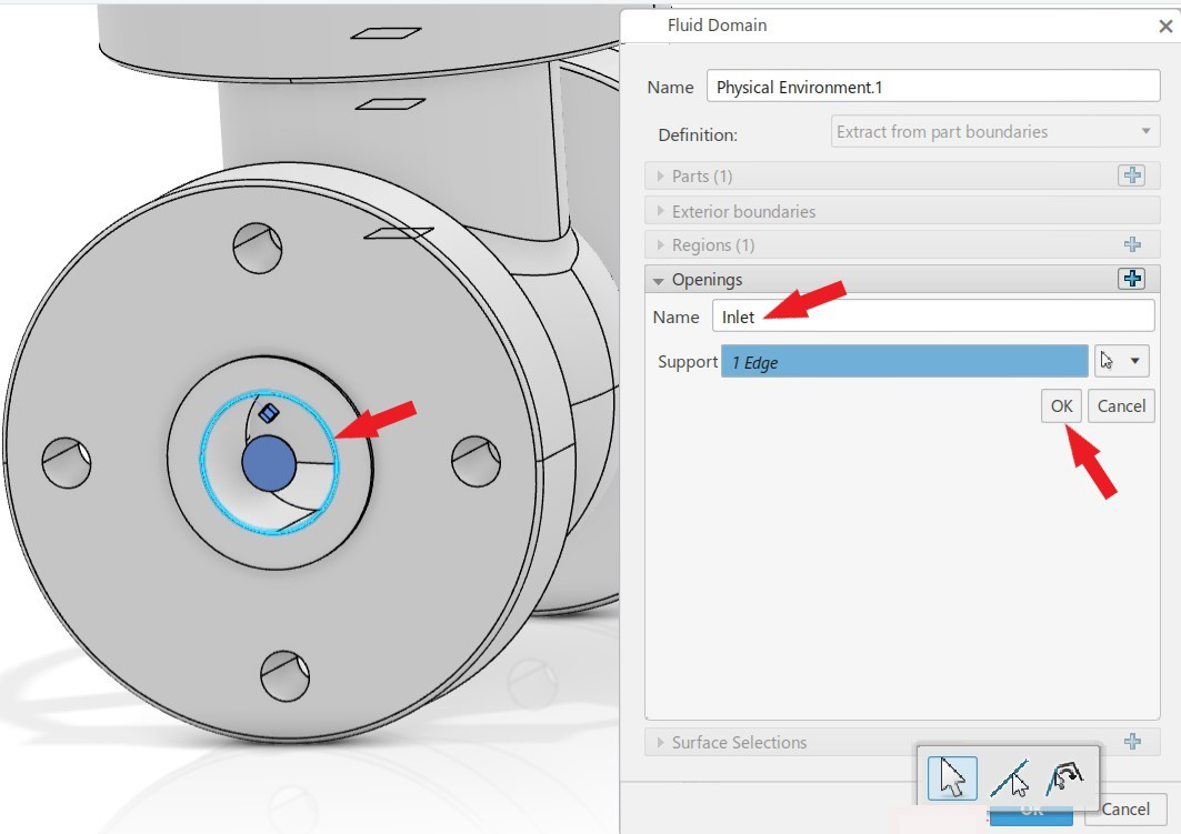
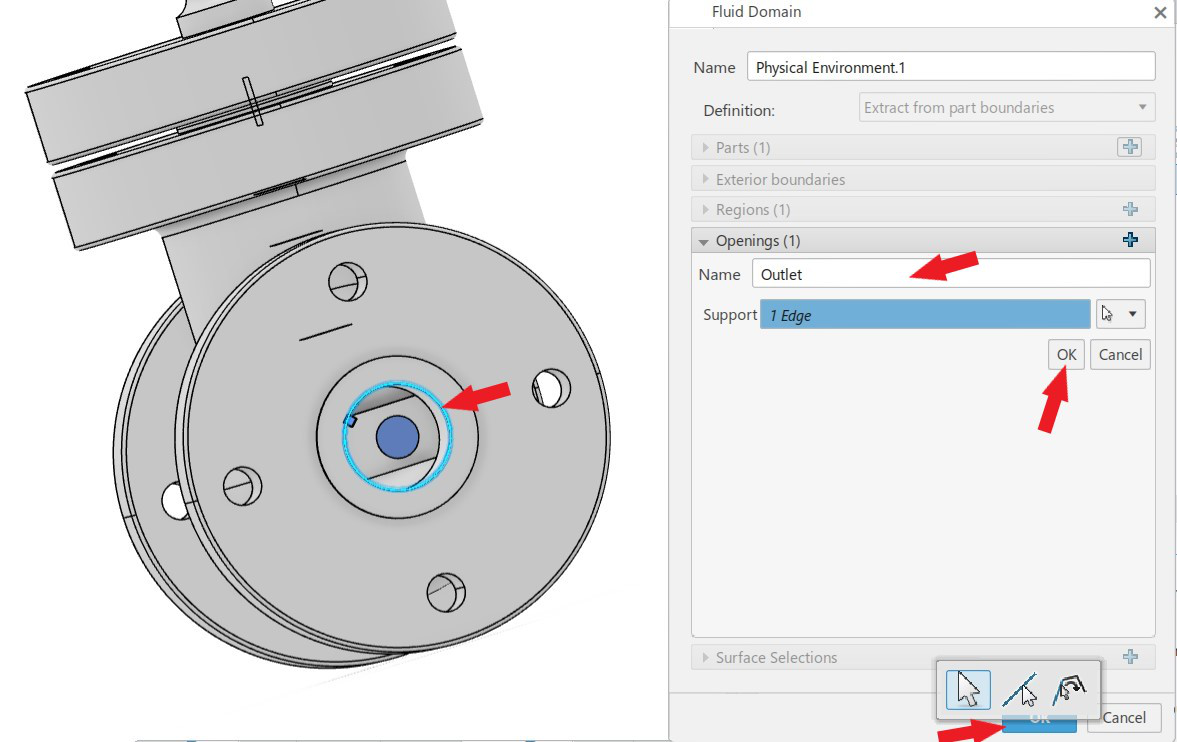
Defining openings is necessary in any sort of internal flow analysis such as pipe flow, valve etc. Type ‘inlet’ in the name section and select the inner circle at left opening which should be defined as inlet. Click ‘ok’ then. Similarly define the other opening and name it as ‘outlet’. Click ‘ok’ at the end of fluid domain dialogue box then.
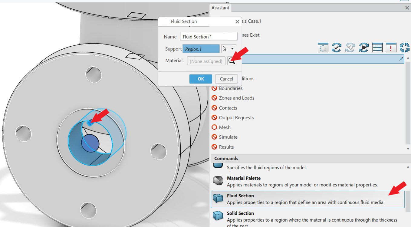
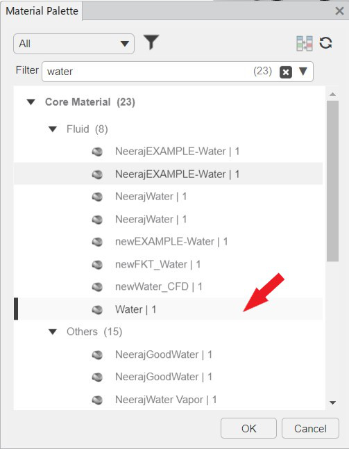
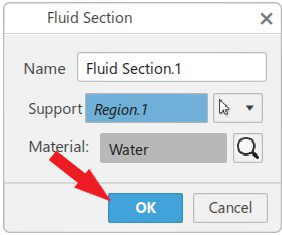
Going back to the model section in user assistant, click on fluid section. In the fluid section dialogue box, select the defined fluid region as support (click on blue glyph). Now select water as material. Click ‘ok’ then.

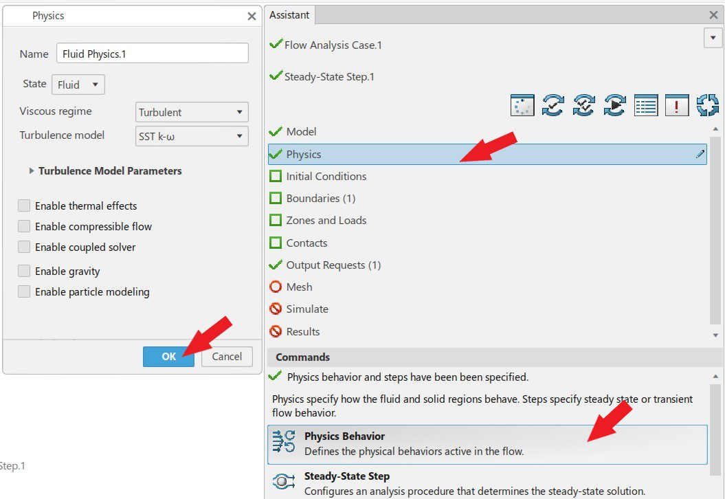
The fluid model is defined fully now. A green tick mark left to model in user assistant confirms the same. Now, the fluid Physics must be defined. Click on Physics and section and keep default SST k-ω as the turbulence model and read different effects such as thermal, compressible flow, gravity and particle modelling etc. The thermal, compressible flow, gravity and particle modelling should remain unchecked since those effects are not studied here. After that click ‘ok’.
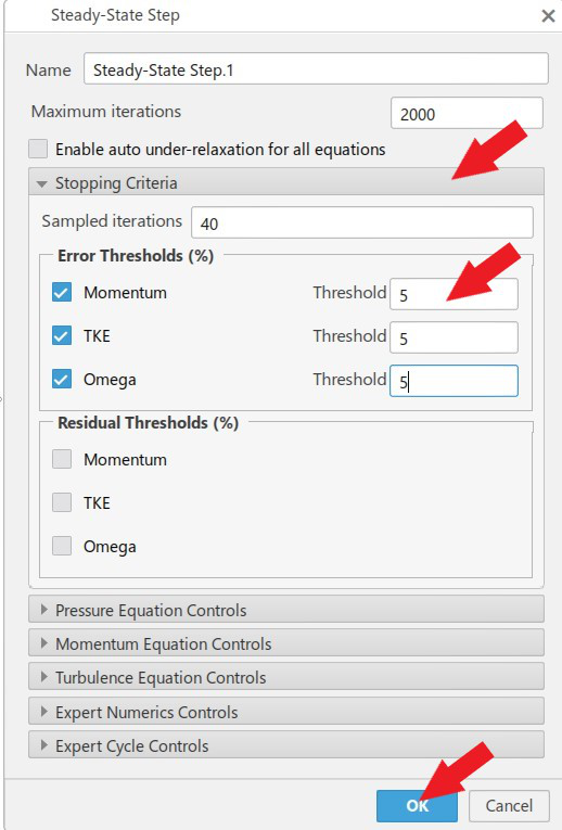
Review the steady state step and change the error thresholds to 5% to make the convergence faster as shown below.
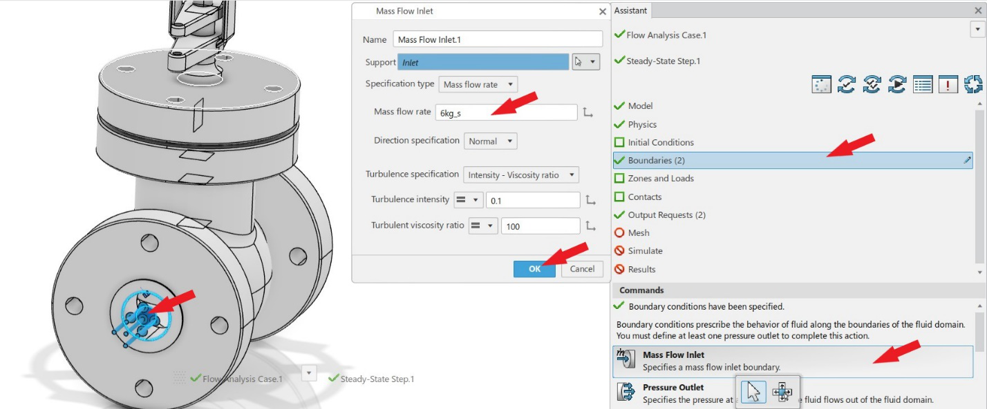
It is observable from the user assistant that a green tick has come to left side of Physics section. The next step is to define the boundary conditions at inlet and outlet. Click on boundary conditions in the assistant. First click on mass flow inlet below in the assistant to define a mass flow to the inlet of valve. Give 6 kg/s as the mass flow rate and select inlet as the opening (you can select the circular blue glyph at inlet from graphics area). Leave other parameters as default and click ‘ok’.
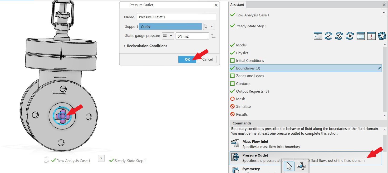
Similarly define a pressure outlet at outlet as shown in figure below. Leave the gauge pressure as zero since the outlet is assumed to be open to atmosphere. Click ‘ok’ then.
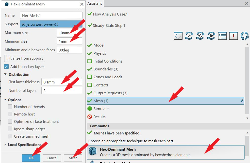
Now the meshing of fluid section must be carried out. There are several types of body fitted meshes available in fluid dynamics engineer such as Hex-dominant, tetrahedron, octree-tetrahedron, sweep-3D, surface meshes etc. For fluid region, Hex dominant mesh is predominantly used. Click on mesh in assistant and then Hex-dominant mesh. In the next dialogue box, specify the maximum and minimum size as 10 and 1 mm respectively. Create 3 boundary layers with 0.1 mm thickness. Click on mesh and meshing will start. After completion, click ‘ok’.
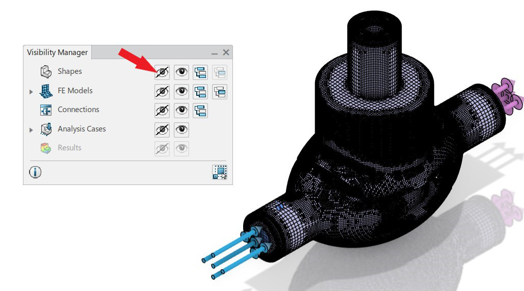
Now, the mesh can be viewed by right clicking in the window and selecting visibility manager. In visibility manager, hide shapes to view the mesh.
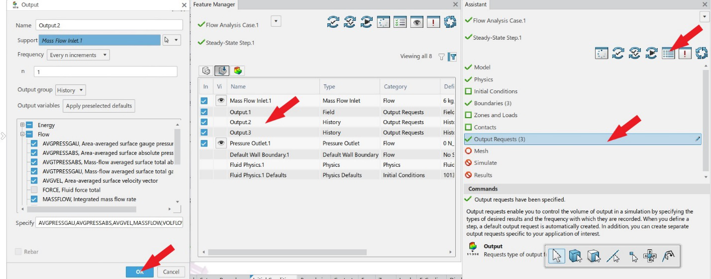
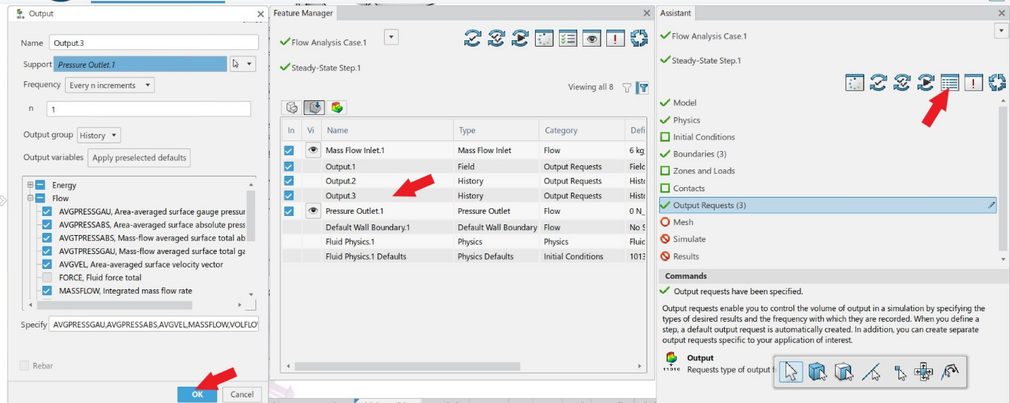
Model and conditions are defined along with the mesh generation. Now before going into simulation, please check the output request. The parameters we want as output can be requested in this section. Click on output request and then click on feature manager in top right of assistant. The feature manager shows all model and scenario setups that has been defined. Double-click on output 2 (for inlet) which is generated by default. Please note that for whole model field output is created. Make sure that average gauge pressure is selected. Check the same for outlet in output 3 also.
Before going into simulation, run the model and scenario checks to confirm there are no errors in the simulation setup. Click on the model and scenario check in the assistant (single tick mark) for the same. The check will be processed and it will show that model and scenario checks are completed with a green arrow. Click ‘ok’ then.
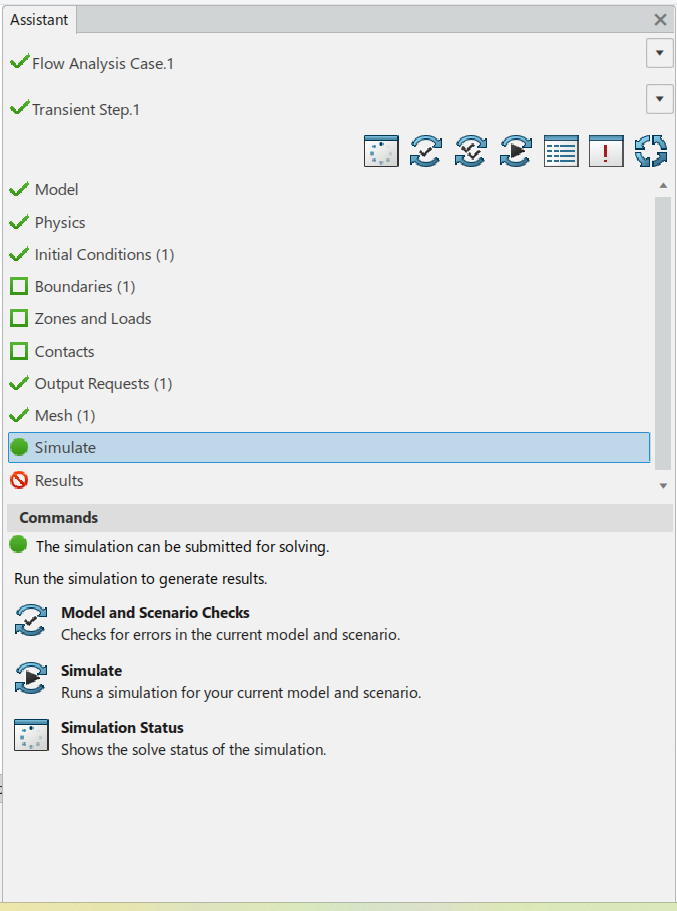
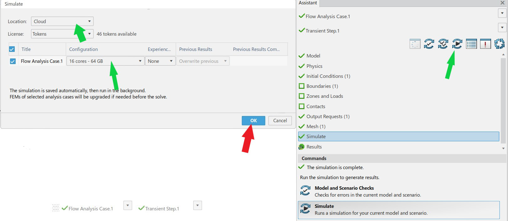
Moving on, the simulation must be carried out now. Click on simulate button on the top of assistant as shown in figure below. The simulation window will be open now. The prime advantage of fluid dynamics engineer is the cloud computing facility. You can run the simulation in cloud using by default available 16 core (for more core, you must purchase tokens) or else by making use of maximum cores available in your system. Click ‘ok’ then and simulation starts now.
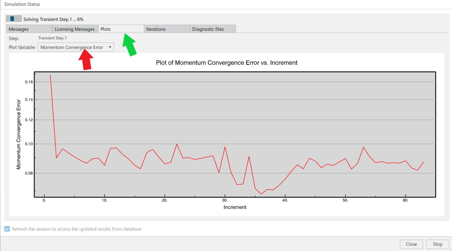
The simulation starts and it will take some amount of time to acquire cloud resources based on the speed of your internet connection. You can monitor different errors and residuals with respect to time in the plots section. Now wait for completion. The advantage of cloud computing is that you can close the simulation window and check after some time in the simulation status button in assistant (left to model and scenario checks). Also, you can stop the simulation in between by clicking on ‘stop’ button.
After the completion, you can close the simulation window and click on results for the post processing.
The post processing and result analysis will be given in lesson-2.
The lesson is finished.
Note: The help and user assistance is available in the ‘?’ icon at top right of platform where you will get all details and assistance in simulation.
We Urge You To Call Us For Any Doubts & Clarifications That You May Have. We Are Eager to Talk To You
Call Us: +91 7406663589
 (No Ratings Yet)
#365/8, Ground Floor, "Hasmitha Avenue", 16th Main, 4th T Block East, Jayanagar, 4th T Block East, Pattabhirama Nagar, Jayanagar, Bengaluru, Karnataka 560041
Rated 4.7/5 with a total of 62 reviews
"CARAX" Building 4th Floor, 105/1/1/4, Next to Radha Hotel, Pune-Mumbai Xpress Way,Baner,Pune 411045
Rated 4.7/5 with a total of 17 reviews
801, 8th Floor, LODHA Supremus, I-Think Techno Campus,Kanjurmarg EAST - MUMBAI, MH, India – 400042.
Rated 5/5 with a total of 51 reviews
501, 5th Floor, Connekt Coworking Space, Gala Argos, Netaji Rd, Ellisbridge, Ahmedabad, Gujarat 380006
Rated 4.1/5 with a total of 7 reviews
Best Engineering Aids & Consultancies Pvt. Ltd. No 306, Karunaa Conclave, 3rd Floor, AD Block, Shanthi Colony, Anna Nagar, Chennai - 600040
Rated 4.6/5 with a total of 16 reviews
Flat no F1, first floor, Nakhate corner, Eknath rang mandir road,New Usmanpura, Aurangabad, 431005.
A-101, 1st Floor, The Hub Complex, opp. Shete Hospital, Mahatma Nagar, Parijat Nagar, Nashik, Maharashtra 422005.
Best Engineering Aids & Consultancies Pvt Ltd (BEACON) Wellwork Workspaces, L1 - 1017A,B, Lower Ground Floor,Vasavi MPM Grand, Ameerpet, Hyderabad, Telangana 500073

pin-up cazino https://azerbaijancuisine.com/# pin-up cazino
pin up casino
reputable mexican pharmacies online northern doctors mexican drugstore online
best online pharmacies in mexico Mexico pharmacy that ship to usa medicine in mexico pharmacies
mexican pharmaceuticals online mexican pharmacy online п»їbest mexican online pharmacies
mexican border pharmacies shipping to usa northern doctors pharmacies in mexico that ship to usa
mexican online pharmacies prescription drugs northern doctors mexican rx online
http://northern-doctors.org/# purple pharmacy mexico price list
reputable mexican pharmacies online: mexican pharmacy – mexican mail order pharmacies
buying prescription drugs in mexico northern doctors reputable mexican pharmacies online
https://northern-doctors.org/# mexican pharmaceuticals online
http://northern-doctors.org/# mexican pharmacy
https://northern-doctors.org/# buying prescription drugs in mexico online
https://northern-doctors.org/# best online pharmacies in mexico
best online pharmacies in mexico mexican pharmacy northern doctors buying from online mexican pharmacy
https://northern-doctors.org/# mexican online pharmacies prescription drugs
https://northern-doctors.org/# mexico drug stores pharmacies
https://northern-doctors.org/# mexican rx online
mexico pharmacies prescription drugs Mexico pharmacy that ship to usa pharmacies in mexico that ship to usa
http://northern-doctors.org/# buying prescription drugs in mexico online
mexico pharmacy cmq pharma medicine in mexico pharmacies
https://cmqpharma.com/# reputable mexican pharmacies online
mexican mail order pharmacies
mexico pharmacies prescription drugs
https://cmqpharma.online/# mexican drugstore online
buying from online mexican pharmacy
medication from mexico pharmacy cmq pharma mexican pharmacy pharmacies in mexico that ship to usa
When I originally commented I clickd the “Notify me when new comments are added” checkbox and now
each time a comment is added I get several e-mails
with the same comment. Is there any way you can remove people from
that service? Many thanks! https://ukrain-forum.biz.ua/
mexico pharmacies prescription drugs cmq mexican pharmacy online mexico pharmacies prescription drugs
purple pharmacy mexico price list mexico pharmacy reputable mexican pharmacies online
п»їbest mexican online pharmacies: mexican pharmacy – mexican online pharmacies prescription drugs
buying prescription drugs in mexico online mexican pharmacy online mexican mail order pharmacies
mexican drugstore online cmq pharma mexican pharmacy medication from mexico pharmacy
buying prescription drugs in mexico cmq pharma mexican online pharmacies prescription drugs
mexican online pharmacies prescription drugs mexican pharmacy mexican rx online
Why Choose FlashUpload.cloud?
It’s going to bee end of mine day, but before finish I am reading this wonderful paragraph to increse my know-how. https://3dwarehouse.sketchup.com/user/46bdc333-281e-4e2c-9322-63de4670b5a6/jetx
I don’t even understand how I finished up right here, but
I thoght this submit was once good. I doo not kknow who you might be
however definitely you’regoing to a faamous blogger for those who aare not already.
Cheers! https://ada.waaron.org/blog/index.php?entryid=398
Quality posts is the key to interest the users to visit the web site, that’s what this web page is providing. http://demo.qkseo.in/viewtopic.php?id=834493
I read this post completely regaarding the comparison of newest aand preceding technologies, it’s remarkable article. https://www.trackyserver.com/profile/155943
Great web site you have here.. It’s difficult to find quality writing like yours
nowadays. I seriouhsly appreciate individuals like you! Take care!! http://demo.qkseo.in/viewtopic.php?id=834504
Everything is verry open with a really clear explanation of the issues.
It was really informative. Your site is extremely helpful.
Thank you for sharing! http://fridayad.in/user/profile/2610646
Link exchange is nothing else however it is just placinbg the other person’s website link on your
page at appropriate place and other person wwill also do similar in favor
of you. https://dev2.emathisi.gr/blog/index.php?entryid=376
Good day! I juswt wish to give youu a big thumbs up forr your excellent information you have got rightt here on this post.I will be returning to your blog for more soon. https://eythar.org/blog/index.php?entryid=484889
I would like to thank you for the eforts you’ve put in writing this site.
I really hope to view the same high-grade blog posts from you later on as well.
In fact, your creative writing abilities has encouhraged mme to get my very own blog now 😉 https://forum.pgbu.ir/viewtopic.php?id=661
https://indiapharmast.com/# indian pharmacy online
mexican rx online п»їbest mexican online pharmacies mexican rx online
mexican border pharmacies shipping to usa buying prescription drugs in mexico buying from online mexican pharmacy
http://foruspharma.com/# mexican border pharmacies shipping to usa
mail order pharmacy india indianpharmacy com pharmacy website india
https://canadapharmast.online/# legit canadian online pharmacy
doxycycline 100mg capsules price in india: doxycycline 500mg – doxycycline hyclate 100mg
amoxicillin 500 mg purchase without prescription: amoxicillin tablet 500mg – amoxicillin brand name
buy cipro online without prescription: ciprofloxacin 500mg buy online – cipro pharmacy
paxlovid covid: п»їpaxlovid – paxlovid generic
amoxicillin cephalexin: amoxicillin pharmacy price – where can i get amoxicillin
paxlovid india: paxlovid cost without insurance – Paxlovid buy online
amoxicillin 500mg capsules price: amoxicillin in india – where can i get amoxicillin
cost of clomid for sale: can you buy generic clomid without a prescription – can i order generic clomid without a prescription
Thanks for the marvelous posting! I actually enjoyed reading
it, you can be a great author.I will make certain to bookmark your blog and will come back sometime soon. I want to encourage yourself to continue
your great job, have a nice weekend!
https://mexicandeliverypharma.com/# pharmacies in mexico that ship to usa
mexican pharmaceuticals online: medicine in mexico pharmacies – purple pharmacy mexico price list
mexican border pharmacies shipping to usa: mexican rx online – mexico drug stores pharmacies
purple pharmacy mexico price list medication from mexico pharmacy best online pharmacies in mexico
mexican border pharmacies shipping to usa: buying from online mexican pharmacy – mexican border pharmacies shipping to usa
purple pharmacy mexico price list: mexican rx online – pharmacies in mexico that ship to usa
https://mexicandeliverypharma.online/# buying from online mexican pharmacy
pharmacies in mexico that ship to usa mexican border pharmacies shipping to usa п»їbest mexican online pharmacies
mexican online pharmacies prescription drugs: mexican pharmaceuticals online – buying prescription drugs in mexico online
п»їbest mexican online pharmacies: buying prescription drugs in mexico online – buying from online mexican pharmacy
http://mexicandeliverypharma.com/# mexican rx online
pharmacies in mexico that ship to usa mexico pharmacies prescription drugs buying from online mexican pharmacy
mexican border pharmacies shipping to usa: п»їbest mexican online pharmacies – medication from mexico pharmacy
mexican mail order pharmacies: best online pharmacies in mexico – mexico pharmacies prescription drugs
best online pharmacies in mexico: п»їbest mexican online pharmacies – mexico drug stores pharmacies
mexican mail order pharmacies mexican pharmaceuticals online mexican border pharmacies shipping to usa
reputable mexican pharmacies online: buying prescription drugs in mexico – mexican pharmaceuticals online
medicine in mexico pharmacies: buying prescription drugs in mexico – п»їbest mexican online pharmacies
п»їbest mexican online pharmacies: mexico drug stores pharmacies – buying prescription drugs in mexico online
http://mexicandeliverypharma.com/# buying prescription drugs in mexico
mexico pharmacy mexico drug stores pharmacies mexican pharmaceuticals online
reputable mexican pharmacies online: mexican rx online – buying prescription drugs in mexico
mexican online pharmacies prescription drugs: purple pharmacy mexico price list – mexican mail order pharmacies
mexico pharmacies prescription drugs: п»їbest mexican online pharmacies – buying prescription drugs in mexico
mexico pharmacies prescription drugs pharmacies in mexico that ship to usa mexico drug stores pharmacies
buying from online mexican pharmacy: mexican drugstore online – medication from mexico pharmacy
pharmacies in mexico that ship to usa: mexican border pharmacies shipping to usa – medication from mexico pharmacy
purple pharmacy mexico price list: mexican border pharmacies shipping to usa – mexico drug stores pharmacies
mexican pharmaceuticals online buying from online mexican pharmacy mexico pharmacy
mexico drug stores pharmacies: mexican border pharmacies shipping to usa – mexican online pharmacies prescription drugs
reputable mexican pharmacies online: mexico drug stores pharmacies – buying prescription drugs in mexico online
п»їbest mexican online pharmacies: mexico pharmacies prescription drugs – medication from mexico pharmacy
medication from mexico pharmacy medication from mexico pharmacy п»їbest mexican online pharmacies
best online pharmacies in mexico: п»їbest mexican online pharmacies – buying from online mexican pharmacy
mexican mail order pharmacies: pharmacies in mexico that ship to usa – best online pharmacies in mexico
buying prescription drugs in mexico online: mexican pharmaceuticals online – mexican border pharmacies shipping to usa
mexico pharmacy pharmacies in mexico that ship to usa reputable mexican pharmacies online
mexican border pharmacies shipping to usa: buying prescription drugs in mexico online – medicine in mexico pharmacies
п»їbest mexican online pharmacies: mexico drug stores pharmacies – mexican mail order pharmacies
buying from online mexican pharmacy: reputable mexican pharmacies online – mexican border pharmacies shipping to usa
mexican pharmacy reputable mexican pharmacies online mexican border pharmacies shipping to usa
mexican border pharmacies shipping to usa: best online pharmacies in mexico – п»їbest mexican online pharmacies
mexico drug stores pharmacies: mexican online pharmacies prescription drugs – medicine in mexico pharmacies
pharmacies in mexico that ship to usa: mexican mail order pharmacies – mexico drug stores pharmacies
mexico drug stores pharmacies buying prescription drugs in mexico mexico drug stores pharmacies
mexico drug stores pharmacies: mexico pharmacies prescription drugs – mexican rx online
mexican mail order pharmacies: mexico drug stores pharmacies – п»їbest mexican online pharmacies
reputable mexican pharmacies online: buying prescription drugs in mexico online – mexico drug stores pharmacies
mexican drugstore online buying prescription drugs in mexico online buying from online mexican pharmacy
mexican online pharmacies prescription drugs: mexican border pharmacies shipping to usa – mexico pharmacies prescription drugs
mexico drug stores pharmacies: buying prescription drugs in mexico – mexico drug stores pharmacies
mexican pharmaceuticals online: best online pharmacies in mexico – mexican border pharmacies shipping to usa
mexico drug stores pharmacies mexican pharmaceuticals online buying from online mexican pharmacy
medication from mexico pharmacy: mexico pharmacies prescription drugs – buying prescription drugs in mexico
reputable mexican pharmacies online: pharmacies in mexico that ship to usa – mexican rx online
medicine in mexico pharmacies: п»їbest mexican online pharmacies – reputable mexican pharmacies online
medicine in mexico pharmacies best online pharmacies in mexico mexico pharmacies prescription drugs
mexican rx online: mexican border pharmacies shipping to usa – mexican drugstore online
medicine in mexico pharmacies: mexico pharmacies prescription drugs – mexican mail order pharmacies
purple pharmacy mexico price list: mexican drugstore online – mexican rx online
best online pharmacies in mexico pharmacies in mexico that ship to usa pharmacies in mexico that ship to usa
best online pharmacies in mexico: mexican border pharmacies shipping to usa – pharmacies in mexico that ship to usa
pharmacies in mexico that ship to usa: medication from mexico pharmacy – mexican border pharmacies shipping to usa
pharmacies in mexico that ship to usa: reputable mexican pharmacies online – medication from mexico pharmacy
medicine in mexico pharmacies mexican pharmacy mexican pharmaceuticals online
Discuss how effective consumer care strategies can cultivate long-term loyalty.
mexico pharmacies prescription drugs: mexican pharmaceuticals online – mexican border pharmacies shipping to usa
pharmacies in mexico that ship to usa: mexico drug stores pharmacies – п»їbest mexican online pharmacies
mexico drug stores pharmacies: reputable mexican pharmacies online – п»їbest mexican online pharmacies
mexican online pharmacies prescription drugs mexico drug stores pharmacies medicine in mexico pharmacies
Wow, fantastic boog structure! How long have you ever been blogging for?
youu made running a blog glance easy. The full glance of your web site is excellent, let alone the content material! https://www.waste-ndc.pro/community/profile/tressa79906983/
mexican mail order pharmacies: buying from online mexican pharmacy – mexican online pharmacies prescription drugs
medication from mexico pharmacy: mexico drug stores pharmacies – п»їbest mexican online pharmacies
medicine in mexico pharmacies: medication from mexico pharmacy – mexican online pharmacies prescription drugs
buying prescription drugs in mexico mexican pharmaceuticals online buying from online mexican pharmacy
mexican rx online: mexico drug stores pharmacies – mexican pharmaceuticals online
buy zithromax 1000 mg online generic zithromax online paypal zithromax antibiotic without prescription
get propecia without insurance: order cheap propecia without prescription – order cheap propecia prices
http://prednisonebestprice.pro/# prednisone 10mg tablet price
https://cytotecbestprice.pro/# buy cytotec in usa
prednisone buy online nz prednisone 1 mg daily prednisone online for sale
cost cheap propecia without dr prescription: cost of propecia price – cost generic propecia online
http://propeciabestprice.pro/# get propecia price
https://cytotecbestprice.pro/# Cytotec 200mcg price
order cytotec online Misoprostol 200 mg buy online Misoprostol 200 mg buy online
cost of generic propecia without prescription: cost of propecia no prescription – cost of generic propecia price
https://nolvadexbestprice.pro/# femara vs tamoxifen
http://nolvadexbestprice.pro/# tamoxifen and depression
should i take tamoxifen should i take tamoxifen tamoxifen hip pain
aromatase inhibitor tamoxifen: nolvadex for pct – clomid nolvadex
cytotec buy online usa: cytotec buy online usa – п»їcytotec pills online
http://cytotecbestprice.pro/# п»їcytotec pills online
prednisone without prescription: order prednisone 100g online without prescription – steroids prednisone for sale
Cytotec 200mcg price: buy cytotec online fast delivery – cytotec buy online usa
http://prednisonebestprice.pro/# buy prednisone online without a prescription
cost generic propecia for sale: cheap propecia tablets – order generic propecia pills
buy propecia for sale: generic propecia pill – get generic propecia without dr prescription
nolvadex pills: common side effects of tamoxifen – where can i buy nolvadex
https://nolvadexbestprice.pro/# tamoxifen depression
farmacie online affidabili: Cialis generico recensioni – comprare farmaci online all’estero
farmacia online senza ricetta: avanafil senza ricetta – farmacia online senza ricetta
https://cialisgenerico.life/# farmacia online piГ№ conveniente
farmacie online autorizzate elenco: kamagra gold – farmacie online affidabili
viagra online in 2 giorni: viagra senza ricetta – viagra pfizer 25mg prezzo
pillole per erezione in farmacia senza ricetta: viagra prezzo – viagra generico recensioni
viagra consegna in 24 ore pagamento alla consegna: viagra prezzo – cialis farmacia senza ricetta
https://viagragenerico.site/# cerco viagra a buon prezzo
top farmacia online: Avanafil 50 mg – top farmacia online
farmacie online affidabili: Cialis generico 20 mg 8 compresse prezzo – Farmacie on line spedizione gratuita
Farmacia online miglior prezzo: avanafil senza ricetta – farmacie online sicure
farmacia online senza ricetta: Cialis generico controindicazioni – farmacie online affidabili
http://farmait.store/# acquisto farmaci con ricetta
migliori farmacie online 2024: Cialis generico controindicazioni – Farmacie online sicure
viagra for sale: buy sildenafil online canada – generic viagra overnight
where to buy generic cialis ?: cheapest tadalafil – cialis without persciction
generic viagra without a doctor prescription: Viagra online price – cheap viagra
http://indiapharmacy.shop/# buy prescription drugs from india
erectile dysfunction medications online
best online pharmacies in mexico: mexico pharmacy win – mexican border pharmacies shipping to usa
Dear beacon-india.com administrator, Your posts are always well-written and engaging.
http://edpillpharmacy.store/# ed drugs online
online ed treatments
reputable mexican pharmacies online: mexico pharmacy win – mexican online pharmacies prescription drugs
http://edpillpharmacy.store/# online prescription for ed
online ed medicine
buy ed pills: ED meds online with insurance – where can i buy erectile dysfunction pills
indian pharmacy paypal: Top online pharmacy in India – top 10 online pharmacy in india
https://indiapharmacy.shop/# indian pharmacy online
mexican mail order pharmacies: Mexico pharmacy online – mexican pharmaceuticals online
mexico drug stores pharmacies: Best pharmacy in Mexico – purple pharmacy mexico price list
online shopping pharmacy india: Top mail order pharmacies – online shopping pharmacy india
http://mexicopharmacy.win/# mexican pharmaceuticals online
mexican pharmaceuticals online: Mexico pharmacy online – medicine in mexico pharmacies
india pharmacy: Online India pharmacy – top online pharmacy india
buy ed meds online: Cheap ED pills online – online ed medicine
https://indiapharmacy.shop/# Online medicine home delivery
pharmacy website india: Online India pharmacy – indian pharmacy paypal
erectile dysfunction pills for sale: Cheap ED pills online – buy ed pills online
reputable indian pharmacies: Best Indian pharmacy – best online pharmacy india
https://indiapharmacy.shop/# п»їlegitimate online pharmacies india
mexican mail order pharmacies: Mexico pharmacy online – buying prescription drugs in mexico online
best ed pills online: Best ED pills non prescription – pills for erectile dysfunction online
best online ed medication: ed pills online – online erectile dysfunction
ed online prescription: Best ED pills non prescription – ed medications cost
buy prescription drugs from india: Indian pharmacy online – world pharmacy india
online shopping pharmacy india: Top mail order pharmacies – indian pharmacy paypal
buy cytotec over the counter https://furosemide.win/# lasix
lasix pills
lasix generic: furosemide online – furosemide 40mg
nolvadex half life buy tamoxifen citrate tamoxifen and weight loss
Chennai Super Kings (CSK) IPO News Good to see Naveen Dhamulingam S in some of the photos рџ‘ЌрџЏ»рџЋ‰рџЏЏ Deposit options: Neteller, Skrill, AstroPay, PaySafe card, Cash vouchers, BetBeard vouchers, and Bitcoin and other cryptocurrencies. The Securities and Exchange Commission, SEC is a Government Agency Mandated to Regulate and Develop the Nigerian Capital Market Good to see Naveen Dhamulingam S in some of the photos рџ‘ЌрџЏ»рџЋ‰рџЏЏ This instrument is issued by corporate bodies and the investors rank second (after bond holders) on the scale of preference when a company goes under. The instrument possesses the characteristics of equity in the sense that when the authorised share capital and paid up capital are being calculated, they are added to equity capital to arrive at the total. Preference shares can also be treated as a debt instrument as they do not confer voting rights on its holders and have a dividend payment that is structured like interest (coupon) paid for bonds issues.
https://pasteldirectory.com/listings12783624/mystic-lake-casino-hotel-news
Now you get to choose how you get rewarded for spending within Mystic Slots! Link your Club M card in the Mystic Slots app and start earning Mystic Slots Loyalty Points redeemable for hotel stays, dining credits, entertainment tickets, gifts, Mystic Slots coin packages, Club M Bonus Point packs and more! Copyright 2024 Pechanga Resort Casino. All Rights Reserved. Beal shared that everyone came around her to celebrate her big win before she hit the service button on the slot machine. Playing on a gambling machine is playing a game of chance. There are often many millions of different possible outcomes of a game. The chances of getting a particular prize outcome may vary significantly for each game. Not all games or machines have the same number of possible outcomes.
lasix dosage: lasix generic name – furosemide 100 mg
tamoxifen lawsuit buy tamoxifen online tamoxifen
buy misoprostol over the counter https://lipitor.guru/# pfizer lipitor
lasix furosemide
Cytotec 200mcg price: cytotec best price – purchase cytotec
cytotec online https://tamoxifen.bid/# tamoxifen men
lasix online
Abortion pills online buy cytotec online buy cytotec online fast delivery
https://cytotec.pro/# п»їcytotec pills online
п»їcytotec pills online https://tamoxifen.bid/# nolvadex pills
lasix pills
ремонт айфона на дому в москве
lasix 100mg: generic lasix – lasix pills
http://lipitor.guru/# buy cheap lipitor
п»їcytotec pills online https://furosemide.win/# lasix pills
lasix generic name
tamoxifen citrate pct: buy tamoxifen citrate – tamoxifen cost
buy cytotec over the counter: buy cytotec online – Abortion pills online
http://furosemide.win/# lasix dosage
purchase cytotec http://lipitor.guru/# cost of generic lipitor in canada
lasix uses
tamoxifen estrogen: buy tamoxifen citrate – clomid nolvadex
Cytotec 200mcg price: buy cytotec online – cytotec abortion pill
Abortion pills online https://cytotec.pro/# buy cytotec over the counter
lasix generic
furosemide 40 mg: buy furosemide – furosemide
zestril 5 mg: buy lisinopril – zestril 10 mg
buy cytotec pills https://tamoxifen.bid/# tamoxifen therapy
lasix furosemide 40 mg
order cytotec online: Misoprostol price in pharmacy – п»їcytotec pills online
lipitor prescription cost: cheapest ace inhibitor – lipitor 80 mg daily
cytotec buy online usa http://cytotec.pro/# buy misoprostol over the counter
lasix 100 mg tablet
cytotec buy online usa: cytotec buy online usa – buy cytotec in usa
furosemide 100mg: lasix 100mg – lasix tablet
Abortion pills online https://lisinopril.guru/# buy 40 mg lisinopril
lasix medication
сервисный центр мобильных телефонов
medication from mexico pharmacy mexican border pharmacies shipping to usa best online pharmacies in mexico
https://easyrxcanada.online/# canada drugs reviews
canadian pharmacies compare: cheap canadian pharmacy – canadian pharmacy
http://easyrxcanada.com/# canadian drug prices
world pharmacy india cheapest online pharmacy india reputable indian online pharmacy
buy medicines online in india: online shopping pharmacy india – reputable indian pharmacies
http://easyrxcanada.com/# online canadian drugstore
india pharmacy mail order best online pharmacy india india pharmacy
best canadian online pharmacy reviews: canadadrugpharmacy com – canadian discount pharmacy
canadianpharmacyworld: canadian pharmacy phone number – safe canadian pharmacies
http://mexstarpharma.com/# buying prescription drugs in mexico
https://easyrxcanada.com/# canadian pharmacy no scripts
pharmacies in mexico that ship to usa: mexico pharmacies prescription drugs – mexico drug stores pharmacies
canadian pharmacy ratings: canadian world pharmacy – ed drugs online from canada
ремонт телевизоров в москве
Профессиональный сервисный центр по ремонту сотовых телефонов, смартфонов и мобильных устройств.
Мы предлагаем: ремонт телефонов
Наши мастера оперативно устранят неисправности вашего устройства в сервисе или с выездом на дом!
world pharmacy india: Online medicine order – reputable indian online pharmacy
https://mexstarpharma.com/# mexican drugstore online
Профессиональный сервисный центр по ремонту ноутбуков, макбуков и другой компьютерной техники.
Мы предлагаем:ремонт макбук в москве
Наши мастера оперативно устранят неисправности вашего устройства в сервисе или с выездом на дом!
slot kumar siteleri: deneme bonusu veren siteler – canl? slot siteleri
http://sweetbonanza.network/# sweet bonanza yorumlar
Профессиональный сервисный центр по ремонту квадрокоптеров и радиоуправляемых дронов.
Мы предлагаем:ремонт дрона
Наши мастера оперативно устранят неисправности вашего устройства в сервисе или с выездом на дом!
en yeni slot siteleri: casino slot siteleri – slot siteleri 2024
http://sweetbonanza.network/# sweet bonanza slot
Профессиональный сервисный центр по ремонту ноутбуков, imac и другой компьютерной техники.
Мы предлагаем:сервисный ремонт imac
Наши мастера оперативно устранят неисправности вашего устройства в сервисе или с выездом на дом!
Профессиональный сервисный центр по ремонту ноутбуков и компьютеров.дронов.
Мы предлагаем:отремонтировать ноутбук
Наши мастера оперативно устранят неисправности вашего устройства в сервисе или с выездом на дом!
ремонтный сервис apple
slot bahis siteleri: guvenilir slot siteleri – slot casino siteleri
http://sweetbonanza.network/# sweet bonanza siteleri
bonus veren casino slot siteleri: slot siteleri – yasal slot siteleri
http://denemebonusuverensiteler.win/# bonus veren siteler
oyun siteleri slot: slot oyun siteleri – en iyi slot siteleri 2024
I’ve been surfing online more than three hours as of late, but I by no means discovered any interesting article like yours. It is beautiful worth sufficient for me. Personally, if all website owners and bloggers made just right content material as you probably did, the web will likely be a lot more useful than ever before. “Now I see the secret of the making of the best persons.” by Walt Whitman.
apple watch ремонт
en guvenilir slot siteleri: en cok kazandiran slot siteleri – yasal slot siteleri
http://denemebonusuverensiteler.win/# deneme bonusu veren siteler
Профессиональный сервисный центр по ремонту планетов в том числе Apple iPad.
Мы предлагаем: ремонт айпадов в москве
Наши мастера оперативно устранят неисправности вашего устройства в сервисе или с выездом на дом!
Профессиональный сервисный центр по ремонту ноутбуков и компьютеров.дронов.
Мы предлагаем:ремонт ноутбуков в москве недорого
Наши мастера оперативно устранят неисправности вашего устройства в сервисе или с выездом на дом!
slot siteleri bonus veren: deneme bonusu veren slot siteleri – en iyi slot siteleri 2024
Профессиональный сервисный центр по ремонту бытовой техники с выездом на дом.
Мы предлагаем:ремонт крупногабаритной техники в петрбурге
Наши мастера оперативно устранят неисправности вашего устройства в сервисе или с выездом на дом!
Профессиональный сервисный центр по ремонту радиоуправляемых устройства – квадрокоптеры, дроны, беспилостники в том числе Apple iPad.
Мы предлагаем: ремонт дронов в москве
Наши мастера оперативно устранят неисправности вашего устройства в сервисе или с выездом на дом!
Если вы искали где отремонтировать сломаную технику, обратите внимание – сервис центр в петербурге
Если вы искали где отремонтировать сломаную технику, обратите внимание – выездной ремонт бытовой техники в екатеринбурге
1xbet скачать: 1хбет – 1xbet скачать
pin up casino: пин ап казино – пинап казино
1хбет зеркало 1xbet официальный сайт 1xbet официальный сайт
http://vavada.auction/# vavada
Если вы искали где отремонтировать сломаную технику, обратите внимание – ремонт бытовой техники в москве
зеркало 1хбет: 1xbet – 1xbet
пин ап казино: пинап казино – пин ап вход
http://vavada.auction/# вавада рабочее зеркало
вавада: вавада – вавада рабочее зеркало
pin up казино: пин ап вход – пин ап вход
ван вин: 1win вход – 1вин сайт
https://1xbet.contact/# 1xbet скачать
Если вы искали где отремонтировать сломаную технику, обратите внимание – ремонт бытовой техники в новосибирске
Профессиональный сервисный центр по ремонту Apple iPhone в Москве.
Мы предлагаем: качественный ремонт айфонов в москве
Наши мастера оперативно устранят неисправности вашего устройства в сервисе или с выездом на дом!
ремонт телефонов москва дешево
мастерская по ремонту телевизоров в москве
Профессиональный сервисный центр по ремонту источников бесперебойного питания.
Мы предлагаем: ремонт ибп в москве
Наши мастера оперативно устранят неисправности вашего устройства в сервисе или с выездом на дом!
пинап казино: пинап казино – пин ап казино вход
Если вы искали где отремонтировать сломаную технику, обратите внимание – профи услуги
Если вы искали где отремонтировать сломаную технику, обратите внимание – ремонт техники в челябинске
вавада рабочее зеркало: vavada online casino – казино вавада
Профессиональный сервисный центр по ремонту варочных панелей и индукционных плит.
Мы предлагаем: срочный ремонт варочной панели
Наши мастера оперативно устранят неисправности вашего устройства в сервисе или с выездом на дом!
Профессиональный сервисный центр по ремонту бытовой техники с выездом на дом.
Мы предлагаем:ремонт крупногабаритной техники в екатеринбурге
Наши мастера оперативно устранят неисправности вашего устройства в сервисе или с выездом на дом!
https://pharm24on.com/# valtrex mexico pharmacy
buy cialis bangkok pharmacy
callao pharmacy generic viagra: Hyzaar – online pharmacy tadalafil
ремонт фототехники москва
https://drstore24.com/# tri luma online pharmacy
levitra pharmacy prices
botox online pharmacy: mexican pharmacy viagra – seroquel xr online pharmacy
https://onlineph24.com/# tricare pharmacy viagra
target pharmacy viagra
buy latisse online pharmacy: viagra price pharmacy – best online international pharmacies
is pharmacy rx one legitimate: parlodel online pharmacy – misoprostol in pharmacy
Если вы искали где отремонтировать сломаную технику, обратите внимание – ремонт бытовой техники в челябинске
https://drstore24.com/# pharmacy class online
how much does percocet cost at the pharmacy
wegmans pharmacy free lipitor: online pharmacy program – ambien mexican pharmacy
Pertama, pada poin ini mengapa Anda harus memilih situs slot gacor terpercaya? Banyaknya situs judi slot pada pencarian google belum memiliki lisensi resmi, situs abal-abal tidak akan membayar kemenangan Anda. Berbeda dengan situs judi slot terpercaya, agen slot akan membayar seluruh kemenangan Anda secara lunas. Apabila Anda ingin mencari situs judi slot terpercaya kalian bisa mengunjungi slot138 untuk bermain slot online. Jika anda memilih untuk bermain di situs permainan RTP Agen138 yang tidak bonafit, anda dapat membuat banyak kerugian dengan ketidakjelasan situs slot gacor. Namun sebaliknya, jika anda memilih situs slot yang tepat seperti Agen138. Dimana banyak keuntungan untuk bisa didapatkan oleh seorang pemain, baik itu pemain baru maupun pemain lama yang setia bermain di situs Agen138. Berikut 4 keuntungan besar untuk anda dapatkan sebagai pemain situs judi info bocoran slot gacor:
http://www.babelcube.com/user/troy-tate
We develop Crypto Casino software in Bitcoin and USDT our games catalog consists of over 30,000 titles all usable through the main online channels and are also suitable for the metaverse: Our online casino software is developed to make gambling experience exciting to the gamers. We provide online casino software solutions, so that the players or clients will be able to deposit their money into an account that can be used in playing for a particular casino. When it comes to online casino platforms, there are several key players that dominate the market. Some of the most popular platforms include Bet365, Betway, 888 Casino, and LeoVegas. These platforms offer a wide range of games, secure payment options, and a user-friendly experience for players.
xlpharmacy generic cialis: pharmacy cialis viagra – one rx pharmacy
Профессиональный сервисный центр по ремонту фото техники от зеркальных до цифровых фотоаппаратов.
Мы предлагаем: ремонт фотоаппаратов
Наши мастера оперативно устранят неисправности вашего устройства в сервисе или с выездом на дом!
xenical indian pharmacy: cialis online pharmacy scams – internet pharmacy manitoba
lorazepam pharmacy online: inhouse pharmacy depo provera – cheapest pharmacy to buy cialis
indian pharmacy indian pharmacy online mail order pharmacy india
mometasone online pharmacy: online pharmacy cellcept – mexican viagra pharmacy
Если вы искали где отремонтировать сломаную технику, обратите внимание – ремонт бытовой техники
Профессиональный сервисный центр по ремонту планшетов в Москве.
Мы предлагаем: замена стекла на планшете цена
Наши мастера оперативно устранят неисправности вашего устройства в сервисе или с выездом на дом!
medication from mexico pharmacy: mexico pharmacies prescription drugs – п»їbest mexican online pharmacies
reputable mexican pharmacies online: mexican drugstore online – mexican drugstore online
Профессиональный сервисный центр по ремонту бытовой техники с выездом на дом.
Мы предлагаем:ремонт бытовой техники в новосибирске
Наши мастера оперативно устранят неисправности вашего устройства в сервисе или с выездом на дом!
india pharmacy india pharmacy mail order pharmacy india
https://mexicopharmacy.cheap/# mexican drugstore online
modafinil online pharmacy: accutane mexican pharmacy – pharmacy mall online reviews
I am actually happy to read this website posts which carries tons of valuable facts, thanks for providing these
kinds of data.
Если вы искали где отремонтировать сломаную технику, обратите внимание – ремонт бытовой техники
india pharmacy mail order: top 10 online pharmacy in india – india pharmacy mail order
top 10 pharmacies in india world pharmacy india online pharmacy india
mexican border pharmacies shipping to usa: pharmacies in mexico that ship to usa – mexican online pharmacies prescription drugs
http://indianpharmacy.company/# indianpharmacy com
Профессиональный сервисный центр по ремонту видео техники а именно видеокамер.
Мы предлагаем: ремонт камер видеонаблюдения
Наши мастера оперативно устранят неисправности вашего устройства в сервисе или с выездом на дом!
top 10 online pharmacy in india: buy medicines online in india – world pharmacy india
Online medicine order: cheapest online pharmacy india – indian pharmacies safe
best online pharmacies in mexico mexican online pharmacies prescription drugs mexico drug stores pharmacies
Если вы искали где отремонтировать сломаную технику, обратите внимание – ремонт техники в красноярске
discount pharmacy: malaysia pharmacy store – cellcept online pharmacy
top 10 online pharmacy in india best india pharmacy best india pharmacy
top 10 online pharmacy in india: cheapest online pharmacy india – Online medicine order
Профессиональный сервисный центр по ремонту бытовой техники с выездом на дом.
Мы предлагаем: ремонт крупногабаритной техники в москве
Наши мастера оперативно устранят неисправности вашего устройства в сервисе или с выездом на дом!
Если вы искали где отремонтировать сломаную технику, обратите внимание – ремонт техники в нижнем новгороде
world pharmacy india: top 10 online pharmacy in india – india online pharmacy
tesco pharmacy fluconazole hydroxyzine online pharmacy uk pharmacy no prescription
https://mexicopharmacy.cheap/# mexico drug stores pharmacies
buying prescription drugs in mexico: mexican drugstore online – buying prescription drugs in mexico online
Если вы искали где отремонтировать сломаную технику, обратите внимание – профи тех сервис новосибирск
п»їlegitimate online pharmacies india: world pharmacy india – indian pharmacy
purple pharmacy mexico price list mexican online pharmacies prescription drugs mexico pharmacies prescription drugs
http://indianpharmacy.company/# reputable indian online pharmacy
phenergan uk pharmacy: Aebgkeymn – femara online pharmacy
mexican mail order pharmacies: buying prescription drugs in mexico online – reputable mexican pharmacies online
Профессиональный сервисный центр по ремонту стиральных машин с выездом на дом по Москве.
Мы предлагаем: сервисный ремонт стиральных машин
Наши мастера оперативно устранят неисправности вашего устройства в сервисе или с выездом на дом!
Профессиональный сервисный центр по ремонту бытовой техники с выездом на дом.
Мы предлагаем: ремонт крупногабаритной техники в казани
Наши мастера оперативно устранят неисправности вашего устройства в сервисе или с выездом на дом!
flovent online pharmacy boots pharmacy diflucan humana rx pharmacy
Pamelor: legal online pharmacy review – online pharmacy no presc uk
п»їbest mexican online pharmacies best online pharmacies in mexico mexico pharmacies prescription drugs
https://mexicopharmacy.cheap/# п»їbest mexican online pharmacies
reputable indian online pharmacy: pharmacy website india – reputable indian pharmacies
Если вы искали где отремонтировать сломаную технику, обратите внимание – сервис центр в перми
buying prescription drugs in mexico online: purple pharmacy mexico price list – п»їbest mexican online pharmacies
online pharmacy generic cialis peoples pharmacy blink online pharmacy
Online medicine home delivery: Online medicine order – best india pharmacy
https://indianpharmacy.company/# top online pharmacy india
online shopping pharmacy india: top online pharmacy india – indianpharmacy com
Профессиональный сервисный центр по ремонту бытовой техники с выездом на дом.
Мы предлагаем: ремонт бытовой техники в москве
Наши мастера оперативно устранят неисправности вашего устройства в сервисе или с выездом на дом!
Online medicine home delivery best online pharmacy india top online pharmacy india
Если вы искали где отремонтировать сломаную технику, обратите внимание – сервисный центр в ростове на дону
mexican rx online: mexico drug stores pharmacies – mexican border pharmacies shipping to usa
best online pharmacies in mexico: purple pharmacy mexico price list – medication from mexico pharmacy
top 10 online pharmacy in india indianpharmacy com buy prescription drugs from india
Профессиональный сервисный центр по ремонту игровых консолей Sony Playstation, Xbox, PSP Vita с выездом на дом по Москве.
Мы предлагаем: срочный ремонт игровой консоли
Наши мастера оперативно устранят неисправности вашего устройства в сервисе или с выездом на дом!
Профессиональный сервисный центр по ремонту компьютерных видеокарт по Москве.
Мы предлагаем: ремонт видеокарт
Наши мастера оперативно устранят неисправности вашего устройства в сервисе или с выездом на дом!
Online medicine order: top 10 online pharmacy in india – Online medicine order
Hello i am kavin, its my first occasion to commenting anywhere, when i read
this paragraph i thought i could also create comment due to this good
post.
Профессиональный сервисный центр по ремонту фототехники в Москве.
Мы предлагаем: ремонт фотовспышек с гарантией
Наши мастера оперативно устранят неисправности вашего устройства в сервисе или с выездом на дом!
Подробнее на сайте сервисного центра remont-vspyshek-realm.ru
Профессиональный сервисный центр по ремонту компьютероной техники в Москве.
Мы предлагаем: сервисный ремонт компьютеров
Наши мастера оперативно устранят неисправности вашего устройства в сервисе или с выездом на дом!
Профессиональный сервисный центр по ремонту фото техники от зеркальных до цифровых фотоаппаратов.
Мы предлагаем: ремонт лампы проектора
Наши мастера оперативно устранят неисправности вашего устройства в сервисе или с выездом на дом!
starzbet guncel giris starzbet guvenilir mi starzbet
http://starzbet.shop/# starzbet guncel giris
Если кто ищет место, где можно выгодно купить раковины и ванны, рекомендую один интернет-магазин, который недавно открыл для себя. Они предлагают большой выбор сантехники и аксессуаров для ванной комнаты. Ассортимент включает различные модели, так что можно подобрать под любой стиль и размер помещения.
Мне нужно было раковина в ванную комнату купить , и они предложили несколько отличных вариантов. Цены приятно удивили, а качество товаров на высшем уровне. Также понравилось, что они предлагают услуги профессиональной установки. Доставка была быстрой, и всё прошло гладко. Теперь моя ванная комната выглядит просто великолепно!
Профессиональный сервисный центр по ремонту компьютерных блоков питания в Москве.
Мы предлагаем: ремонт блоков питания
Наши мастера оперативно устранят неисправности вашего устройства в сервисе или с выездом на дом!
Недавно разбил экран своего телефона и обратился в этот сервисный центр. Ребята быстро и качественно починили устройство, теперь работает как новый. Очень рекомендую обратиться к ним за помощью. Вот ссылка на их сайт: сервис по починке телефонов.
сервис профи самара
<a href=”https://remont-kondicionerov-wik.ru”>ремонт кондиционеров</a>
Профессиональный сервисный центр по ремонту компьютероной техники в Москве.
Мы предлагаем: качественный ремонт компьютеров
Наши мастера оперативно устранят неисправности вашего устройства в сервисе или с выездом на дом!
Business Solutions including all features. We’ll help you navigate the crypto market smoothly and get access to all the popular coins like Bitcoin, Ethereum, Litecoin and many more. The methodology by Themetafriend uses node distribution to determine Bitcoin users. It should be noted, however, that such a methodology might not show the entire spectrum of adopting technology as multifaceted as Bitcoin. Digital & Trend reports Founder Michael Dell announces on Twitter that dell now accepts Bitcoin. Customers in the United States (only) can purchase any product listed on Dell’s online marketplace using Bitcoin. All Bitcoin transactions are to be handled by Coinbase, a Bitcoin payment processor. At a yearly revenue of $56 billion, Dell becomes the largest company to accept Bitcoin. 1.3.1.1. Bitcoin – Network status and alerts
https://www.xploredomains.com/2024-07-13?page=2
LocalBitcoins is a peer-to-peer Bitcoin exchange. It is a marketplace where users can buy and sell Bitcoins to and from each other. Users, called traders, create advertisements with the price and the payment method they want to offer. You can choose to buy from sellers from a certain nearby region on the platform. is after all a good place to go to buy Bitcoins when you can’t find your desired payment methods anywhere else. But prices are usually higher on this platform and you have to do your due diligence to avoid getting scammed. After you have a funded account, navigate to Avalanche (AVAX). You cannot purchase TIME directly, so you need to have another currency to swap for TIME. The easiest cryptocurrency to use is AVAX, as you’ll be using the Avalanche Blockchain to trade your tokens for Wonderland (TIME).
https://gatesofolympusoyna.online/# gates of olympus oyna demo
gates of olympus oyna gates of olympus demo gates of olympus turkce
Профессиональный сервисный центр по ремонту камер видео наблюдения по Москве.
Мы предлагаем: сервисные центры ремонту камер в москве
Наши мастера оперативно устранят неисправности вашего устройства в сервисе или с выездом на дом!
Профессиональный сервисный центр по ремонту бытовой техники с выездом на дом.
Мы предлагаем: сервисные центры по ремонту техники в нижнем новгороде
Наши мастера оперативно устранят неисправности вашего устройства в сервисе или с выездом на дом!
viagra online rГЎpida comprar viagra se puede comprar sildenafil sin receta
http://farmaciaeu.com/# farmacia online barcelona
farmacia en casa online descuento: comprar cialis online seguro – farmacias online seguras en espaГ±a
https://tadalafilo.bid/# farmacia online barata
farmacia online barcelona
farmacia online madrid: cialis en Espana sin receta contrareembolso – farmacia online 24 horas
farmacias online seguras Comprar Cialis sin receta farmacia online barata y fiable
http://farmaciaeu.com/# farmacia online 24 horas
Профессиональный сервисный центр по ремонту кнаручных часов от советских до швейцарских в Москве.
Мы предлагаем: ремонт часов москва
Наши мастера оперативно устранят неисправности вашего устройства в сервисе или с выездом на дом!
Профессиональный сервисный центр по ремонту бытовой техники с выездом на дом.
Мы предлагаем: сервисные центры по ремонту техники в перми
Наши мастера оперативно устранят неисправности вашего устройства в сервисе или с выездом на дом!
Если вы искали где отремонтировать сломаную технику, обратите внимание – техпрофи
http://farmaciaeu.com/# farmacia online barata
farmacias online seguras
farmacias online baratas: Comprar Cialis sin receta – farmacia online envГo gratis
https://sildenafilo.men/# comprar viagra en espaГ±a envio urgente contrareembolso
farmacia online espaГ±a envГo internacional: tadalafilo – farmacia online barata
farmacia online envГo gratis: farmacia online barata y fiable – farmacias online baratas
http://sildenafilo.men/# viagra para mujeres
farmacias online seguras
se puede comprar sildenafil sin receta: comprar viagra – sildenafil 100mg genГ©rico
Профессиональный сервисный центр по ремонту парогенераторов в Москве.
Мы предлагаем: ремонт парогенераторов замена
Наши мастера оперативно устранят неисправности вашего устройства в сервисе или с выездом на дом!
http://sildenafilo.men/# comprar viagra sin gastos de envГo
comprar viagra en espaГ±a envio urgente: sildenafilo precio – п»їViagra online cerca de Madrid
Если вы искали где отремонтировать сломаную технику, обратите внимание – тех профи
acquisto farmaci con ricetta Cialis generico controindicazioni top farmacia online
farmacie online affidabili Farmacia online miglior prezzo farmacie online autorizzate elenco
new year balloons with logo to order https://balloon-store-dubai.com
п»їFarmacia online migliore: Cialis generico 20 mg 8 compresse prezzo – п»їFarmacia online migliore
farmacie online affidabili: Farmacie online sicure – farmacie online sicure
п»їFarmacia online migliore Farmacie on line spedizione gratuita Farmacia online piГ№ conveniente
pillole per erezione in farmacia senza ricetta: viagra – viagra originale recensioni
Farmacia online piГ№ conveniente Cialis generico prezzo Farmacie online sicure
farmacia online piГ№ conveniente: farmacia online migliore – acquisto farmaci con ricetta
https://tadalafilit.com/# top farmacia online
farmacie online affidabili
Профессиональный сервисный центр по ремонту бытовой техники с выездом на дом.
Мы предлагаем: сервисные центры по ремонту техники в красноярске
Наши мастера оперативно устранят неисправности вашего устройства в сервисе или с выездом на дом!
acquistare farmaci senza ricetta: Cialis generico controindicazioni – migliori farmacie online 2024
farmaci senza ricetta elenco farmacia online migliore Farmacia online piГ№ conveniente
viagra pfizer 25mg prezzo viagra generico viagra consegna in 24 ore pagamento alla consegna
top farmacia online: Farmacie on line spedizione gratuita – comprare farmaci online con ricetta
Если вы искали где отремонтировать сломаную технику, обратите внимание – ремонт бытовой техники
http://tadalafilit.com/# farmacia online piГ№ conveniente
farmacia online
farmacie online autorizzate elenco Farmacie online sicure comprare farmaci online all’estero
farmacie online sicure: Cialis generico 5 mg prezzo – Farmacia online miglior prezzo
pillole per erezioni fortissime: viagra senza prescrizione – le migliori pillole per l’erezione
farmacie online sicure п»їFarmacia online migliore farmacie online affidabili
farmacia online senza ricetta Cialis generico recensioni farmacie online affidabili
Профессиональный сервисный центр по ремонту бытовой техники с выездом на дом.
Мы предлагаем:ремонт бытовой техники в ростове на дону
Наши мастера оперативно устранят неисправности вашего устройства в сервисе или с выездом на дом!
farmacia online: Brufen antinfiammatorio – farmacia online
farmaci senza ricetta elenco Tadalafil generico migliore top farmacia online
ремонт кондиционеров с гарантией
viagra prezzo farmacia 2023 viagra senza prescrizione miglior sito dove acquistare viagra
https://brufen.pro/# BRUFEN 600 acquisto online
migliori farmacie online 2024
top farmacia online: Cialis generico farmacia – farmaci senza ricetta elenco
alternativa al viagra senza ricetta in farmacia: viagra – viagra online spedizione gratuita
miglior sito per comprare viagra online viagra viagra acquisto in contrassegno in italia
farmacia online Cialis generico controindicazioni farmacia online piГ№ conveniente
farmacia online piГ№ conveniente: Brufen antinfiammatorio – Farmacie on line spedizione gratuita
Farmacia online miglior prezzo Ibuprofene 600 prezzo senza ricetta farmaci senza ricetta elenco
top farmacia online: BRUFEN 600 mg 30 compresse prezzo – acquisto farmaci con ricetta
viagra online in 2 giorni acquisto viagra le migliori pillole per l’erezione
farmacia online piГ№ conveniente: Tadalafil generico migliore – farmacia online piГ№ conveniente
Сервисный центр предлагает ремонт холодильника akai на дому ремонт холодильников akai в москве
farmacia online piГ№ conveniente Farmacie on line spedizione gratuita farmacie online affidabili
сервисный центре предлагает мастер по телевизорам – ремонт телевизоров недорого
https://sildenafilit.pro/# viagra cosa serve
farmacia online piГ№ conveniente
Сервисный центр предлагает ремонт видеокарт asus недорого ремонт видеокарты asus адреса
comprare farmaci online con ricetta Farmacia online piu conveniente Farmacia online piГ№ conveniente
kamagra senza ricetta in farmacia: viagra senza prescrizione – cerco viagra a buon prezzo
migliori farmacie online 2024 Cialis generico recensioni Farmacie online sicure
rybelsus: rybelsus cost – Buy semaglutide pills
https://ventolininhaler.pro/# ventolin otc nz
neurontin 600 mg price gabapentin 100mg neurontin 400 mg
furosemide 100mg: furosemide 40 mg – lasix pills
prednisone for dogs: prednisone tabs 20 mg – prednisone buy no prescription
ventolin prices in canada: ventolin uk pharmacy – ventolin inhaler for sale
lasix dosage buy lasix online lasix 100mg
Если вы искали где отремонтировать сломаную технику, обратите внимание – профи ремонт
https://ventolininhaler.pro/# ventolin 4 mg tablets
prednisone 20 mg purchase: 20 mg prednisone – prednisone 5 mg tablet cost
ventolin 100 mg: ventolin script – ventolin australia prescription
generic lasix: furosemide 40 mg – lasix 20 mg
Профессиональный сервисный центр по ремонту компьютеров и ноутбуков в Москве.
Мы предлагаем: ремонт макбуков москва
Наши мастера оперативно устранят неисправности вашего устройства в сервисе или с выездом на дом!
rybelsus generic: rybelsus price – cheap Rybelsus 14 mg
neurontin brand coupon: ordering neurontin online – neurontin 200 mg capsules
https://furosemide.men/# lasix uses
neurontin 800 mg capsules: neurontin 800 mg capsules – cost of neurontin 800 mg
prednisone 2.5 mg: prednisone 20 mg in india – prednisone tablet 100 mg
Semaglutide pharmacy price: cheap Rybelsus 14 mg – semaglutide
http://furosemide.men/# lasix generic
furosemida: cheap lasix – lasix generic
50 mg prednisone canada pharmacy: prednisone 10mg online – 400 mg prednisone
lasix generic name: lasix side effects – generic lasix
Профессиональный сервисный центр по ремонту бытовой техники с выездом на дом.
Мы предлагаем: ремонт крупногабаритной техники в тюмени
Наши мастера оперативно устранят неисправности вашего устройства в сервисе или с выездом на дом!
https://indiadrugs.pro/# online pharmacy india
best online pharmacies in mexico: medicine in mexico pharmacies – pharmacies in mexico that ship to usa
online pharmacy india Indian pharmacy online best india pharmacy
Профессиональный сервисный центр по ремонту кондиционеров в Москве.
Мы предлагаем: ремонт кондиционера москва
Наши мастера оперативно устранят неисправности вашего устройства в сервисе или с выездом на дом!
Профессиональный сервисный центр по ремонту гироскутеров в Москве.
Мы предлагаем: ремонт платы гироскутера
Наши мастера оперативно устранят неисправности вашего устройства в сервисе или с выездом на дом!
Профессиональный сервисный центр по ремонту моноблоков в Москве.
Мы предлагаем: ремонт моноблоков с гарантией
Наши мастера оперативно устранят неисправности вашего устройства в сервисе или с выездом на дом!
reputable indian pharmacies: indian pharmacy – indianpharmacy com
http://mexicanpharma.icu/# mexican online pharmacies prescription drugs
reputable mexican pharmacies online: medication from mexico – mexico drug stores pharmacies
canadian pharmacy no rx needed Canadian Pharmacy canadian pharmacy 24 com
https://canadapharma.shop/# online canadian pharmacy reviews
india online pharmacy: online Indian pharmacy – reputable indian online pharmacy
Профессиональный сервисный центр по ремонту планшетов в том числе Apple iPad.
Мы предлагаем: ремонт айпадов с гарантией
Наши мастера оперативно устранят неисправности вашего устройства в сервисе или с выездом на дом!
http://mexicanpharma.icu/# mexico drug stores pharmacies
india pharmacy: indian pharmacy – Online medicine order
precription drugs from canada Canadian Pharmacy canadian neighbor pharmacy
buying from online mexican pharmacy https://mexicanpharma.icu/# mexico drug stores pharmacies
pharmacies in mexico that ship to usa
https://indiadrugs.pro/# mail order pharmacy india
legit canadian pharmacy legitimate canadian online pharmacies canada drugs online
https://indiadrugs.pro/# india pharmacy
Hiya, I am really glad I have found this info. Nowadays bloggers publish just about gossips and net and this is really frustrating. A good site with exciting content, this is what I need. Thank you for keeping this site, I’ll be visiting it. Do you do newsletters? Can’t find it.
http://mexicanpharma.icu/# mexico drug stores pharmacies
mexican rx online mexican pharma pharmacies in mexico that ship to usa
mexico pharmacies prescription drugs: mexican mail order pharmacies – best online pharmacies in mexico
mexican rx online
п»їpharmacie en ligne france: Cialis generique achat en ligne – Pharmacie Internationale en ligne
I was reading some of your content on this website and I believe this web site is rattling instructive! Retain posting.
Профессиональный сервисный центр по ремонту МФУ в Москве.
Мы предлагаем: гарантийный ремонт мфу
Наши мастера оперативно устранят неисправности вашего устройства в сервисе или с выездом на дом!
https://pharmaciepascher.pro/# Pharmacie Internationale en ligne
Сервисный центр предлагает ремонт квадрокоптера blade в москве ремонт квадрокоптеров blade на дому
pharmacie en ligne livraison europe: pharmacie en ligne – п»їpharmacie en ligne france
Achat mГ©dicament en ligne fiable pharmacie en ligne fiable pharmacie en ligne sans ordonnance
Your article helped me a lot, is there any more related content? Thanks!
http://clssansordonnance.icu/# pharmacie en ligne fiable
Viagra sans ordonnance pharmacie France: Viagra generique en pharmacie – Acheter Sildenafil 100mg sans ordonnance
Профессиональный сервисный центр по ремонту принтеров в Москве.
Мы предлагаем: ремонт принтеров с гарантией
Наши мастера оперативно устранят неисправности вашего устройства в сервисе или с выездом на дом!
Pretty section of content. I just stumbled upon your weblog and in accession capital to assert that I get in fact enjoyed account your blog posts. Any way I will be subscribing to your augment and even I achievement you access consistently rapidly.
Viagra homme prix en pharmacie sans ordonnance: Viagra sans ordonnance 24h – Viagra 100 mg sans ordonnance
Профессиональный сервисный центр по ремонту бытовой техники с выездом на дом.
Мы предлагаем:сервис центры бытовой техники уфа
Наши мастера оперативно устранят неисправности вашего устройства в сервисе или с выездом на дом!
Achat mГ©dicament en ligne fiable pharmacie en ligne sans ordonnance п»їpharmacie en ligne france
Профессиональный сервисный центр по ремонту плоттеров в Москве.
Мы предлагаем: ремонт плоттера в москве
Наши мастера оперативно устранят неисправности вашего устройства в сервисе или с выездом на дом!
Viagra femme sans ordonnance 24h: viagra sans ordonnance – Meilleur Viagra sans ordonnance 24h
Профессиональный сервисный центр по ремонту объективов в Москве.
Мы предлагаем: ремонт объектива фотоаппарата
Наши мастера оперативно устранят неисправности вашего устройства в сервисе или с выездом на дом!
Viagra en france livraison rapide: Viagra prix – Viagra pas cher livraison rapide france
http://clssansordonnance.icu/# pharmacie en ligne pas cher
Achat mГ©dicament en ligne fiable trouver un mГ©dicament en pharmacie pharmacies en ligne certifiГ©es
Профессиональный сервисный центр по ремонту серверов в Москве.
Мы предлагаем: надежный сервис ремонта серверов
Наши мастера оперативно устранят неисправности вашего устройства в сервисе или с выездом на дом!
pharmacie en ligne avec ordonnance: pharmacie en ligne – Pharmacie sans ordonnance
pharmacie en ligne france pas cher: pharmacie en ligne sans ordonnance – vente de mГ©dicament en ligne
п»їpharmacie en ligne france Medicaments en ligne livres en 24h Pharmacie sans ordonnance
Some really great info , Glad I found this.
http://rybelsus.shop/# rybelsus price
buy ozempic: ozempic cost – ozempic generic
http://ozempic.art/# ozempic online
ozempic coupon: Ozempic without insurance – ozempic generic
buy semaglutide pills rybelsus pill buy semaglutide pills
rybelsus cost: semaglutide tablets – buy semaglutide online
ozempic generic: ozempic online – buy cheap ozempic
https://rybelsus.shop/# semaglutide online
semaglutide tablets cheapest rybelsus pills rybelsus coupon
Ozempic without insurance: buy ozempic – ozempic
ozempic: buy ozempic – ozempic generic
http://rybelsus.shop/# rybelsus coupon
https://rybelsus.shop/# semaglutide cost
buy ozempic buy ozempic pills online buy ozempic
cheapest rybelsus pills: buy semaglutide online – rybelsus coupon
Профессиональный сервисный центр по ремонту сетевых хранилищ в Москве.
Мы предлагаем: ремонт сетевого хранилища
Наши мастера оперативно устранят неисправности вашего устройства в сервисе или с выездом на дом!
Профессиональный сервисный центр по ремонту сигвеев в Москве.
Мы предлагаем: ремонт аккумуляторов сигвей в москве
Наши мастера оперативно устранят неисправности вашего устройства в сервисе или с выездом на дом!
https://rybelsus.shop/# semaglutide tablets
http://rybelsus.shop/# rybelsus coupon
rybelsus cost: rybelsus coupon – rybelsus pill
buy rybelsus online buy semaglutide pills semaglutide cost
semaglutide tablets: rybelsus price – rybelsus price
ozempic online ozempic online ozempic coupon
https://rybelsus.shop/# cheapest rybelsus pills
buy cheap ozempic: buy ozempic – ozempic online
https://rybelsus.shop/# buy semaglutide pills
buy ozempic pills online: buy cheap ozempic – ozempic coupon
cheapest rybelsus pills semaglutide tablets buy semaglutide online
Профессиональный сервисный центр по ремонту автомагнитол в Москве.
Мы предлагаем: ремонт автомагнитолы
Наши мастера оперативно устранят неисправности вашего устройства в сервисе или с выездом на дом!
ozempic ozempic online ozempic coupon
ozempic online: buy cheap ozempic – ozempic online
http://ozempic.art/# ozempic
ozempic online Ozempic without insurance ozempic coupon
https://rybelsus.shop/# buy semaglutide pills
ozempic cost: buy ozempic pills online – ozempic
https://rybelsus.shop/# semaglutide cost
ozempic coupon buy cheap ozempic Ozempic without insurance
https://ozempic.art/# buy cheap ozempic
https://rybelsus.shop/# rybelsus coupon
В магазине сейфов предлагают стоимость сейфа купить сейф оптом
rybelsus cost rybelsus cost semaglutide cost
Профессиональный сервисный центр по ремонту планшетов в Москве.
Мы предлагаем: ремонт планшетов москва
Наши мастера оперативно устранят неисправности вашего устройства в сервисе или с выездом на дом!
ozempic online: ozempic coupon – ozempic online
https://rybelsus.shop/# rybelsus pill
buy ozempic pills online buy ozempic ozempic coupon
http://ozempic.art/# Ozempic without insurance
Профессиональный сервисный центр ремонт телефонов в москве где ремонтируют телефоны
pinup az: pin up – pin up
pin up bet pin-up bonanza pin up guncel giris
В магазине сейфов предлагают сейфы второго класса купить сейф 2 класс в москве
пин ап казино: pin up зеркало – пин ап казино вход
You can definitely see your enthusiasm in the work you write. The world hopes for more passionate writers like you who are not afraid to say how they believe. Always go after your heart.
пин ап казино вход: пин ап – пинап кз
http://pinupru.site/# пин ап казино вход
Профессиональный сервисный центр по ремонту бытовой техники с выездом на дом.
Мы предлагаем: ремонт бытовой техники в волгограде
Наши мастера оперативно устранят неисправности вашего устройства в сервисе или с выездом на дом!
пин ап казино онлайн https://pinupkz.tech/# pin up kz
пинап казино
pin up казино пин ап пин ап кз
Riversweeps Casino follows the standard Sweepstakes concept, which means cash redemption is possible. Download your favorite RiverSweeps games to your desktop or mobile device рџ—Ј️ User Review: This casino has given me the biggest payouts and hits. They usually have more unique games on here than the competitors. I think the payouts and frequency are better than actually walking into the casino somewhere. Anytime I have a small issue, customer service helps me on chat. Very conveniently set up. Overall this is a really great app! – James Zvolensky Slot machines are the most popular game in online casinos and on sweepstakes sites. It would not be unreasonable to expect online slots promos in Riversweeps. You can easily access your desired casino games by installing the RSweeps APK app on your Android phone.
http://shironeko-shitaraba.net/wiki/index.php?riasanfita1971
Casino bonus och freespins ger en unikt bra början på ens karriär som casino spelare. Dessa ökar även vinstchanserna. En casino bonus gör helt enkelt att man får spela fler gånger för samma krona. De kan leda till att man får sin insats dubblad, eller att man får ett visst antal gratissnurr. Detta är särskilt bra om man inte känner för att satsa allt för mycket av sina egna pengar. Antalet olika sorters casino bonus och freespins är många. Att välja rätt kan vara skillnaden mellan framgång och förlust. Detta kan däremot vara lite svårt om man inte är säker på hur olika bonusar fungerar. 18+. Applies to new customers. My deposit SEK 100. Bonus option 1: Max bonus SEK 3,000 + 20 spins. Wagering requirements 18x in Casino & Live Casino, 7x on sports min. odds 1.80. Bonus option 2 “The Revenge”: Up to SEK 800 back if you lose on your first bet in the Sportsbook + 20 spins. The spins are free of turnover. Valid for 90 days. Stodlijn.se, Spelpaus.se, Play Responsibly. Terms and conditions apply. Snabbare is a Trustly casino site.
pin-up oyunu: pin up 306 – pin up azerbaijan
пин ап казино онлайн https://pinupkz.tech/# пин ап казахстан
pin up казино
Тут делают продвижение продвижение в поисковых системах медицинского сайта стратегия с роботами
пин ап официальный сайт: пин ап казино – pin up
Тут делают продвижение создание сайта под ключ для медицинского учреждения создание медицинских сайтов под ключ
pin up https://pinupru.site/# pin up зеркало
пинап кз
пин ап пин ап казино пин ап официальный сайт
https://pinupkz.tech/# пинап казино
pin up зеркало: пин ап казино зеркало – пин ап вход
пин ап http://pinupkz.tech/# пин ап
пин ап
В магазине сейфов предлагают купить взломостойкие сейфы сейфы взломостойкие класса
пин ап 634 https://pinupaz.bid/# pin up azerbaijan
пин ап
pin up 306: pinup azerbaycan – pin up casino
pin up bet pin-up casino giris pin-up casino giris
pin up казино http://pinupkz.tech/# пинап кз
пин ап 634
pin up casino giris: pin-up bonanza – pin up
Тут делают продвижение медицинский seo сео продвижение медицинских сайтов
пин ап казино зеркало pin up казино пин ап официальный сайт
Тут делают продвижение разработка сайта клиники разработка медицинских сайтов
Профессиональный сервисный центр по ремонту электросамокатов в Москве.
Мы предлагаем: вызвать мастера по ремонту электросамокатов
Наши мастера оперативно устранят неисправности вашего устройства в сервисе или с выездом на дом!
http://pinupturkey.pro/# pin-up casino giris
пин ап казахстан https://pinupkz.tech/# пин ап 634
пин ап 634
пинап кз: пин ап казахстан – pin up kz
pin up casino pin up azerbaijan pin up azerbaijan
Профессиональный сервисный центр по ремонту бытовой техники с выездом на дом.
Мы предлагаем: сервис центры бытовой техники воронеж
Наши мастера оперативно устранят неисправности вашего устройства в сервисе или с выездом на дом!
Профессиональный сервисный центр сдача телефона в ремонт сервисный центр по ремонту телефонов
Semaglutide pharmacy price rybelsus cost Rybelsus 14 mg price
The best https://bestwebsiteto.com sites on the web to suit your needs. The top-rated platforms to help you succeed in learning new skills
https://zithromax.company/# zithromax for sale online
Тут делают продвижение разработка сайта для медицинского центра разработка сайтов медицинских организаций
Тут делают продвижение создание медицинского сайта разработка медицинских сайтов
Buy compounded semaglutide online rybelsus price buy rybelsus
https://zithromax.company/# zithromax cost uk
https://stromectol.agency/# ivermectin 3mg tablet
amoxicillin 250 mg price in india: buy amoxicillin from canada – buying amoxicillin in mexico
http://semaglutide.win/# Buy compounded semaglutide online
price of neurontin gabapentin for sale neurontin 600 mg price
https://semaglutide.win/# rybelsus generic
generic zithromax online paypal
zithromax capsules australia: zithromax 1000 mg pills – purchase zithromax online
Профессиональный сервисный центр по ремонту моноблоков iMac в Москве.
Мы предлагаем: ремонт imac выезд
Наши мастера оперативно устранят неисправности вашего устройства в сервисе или с выездом на дом!
https://zithromax.company/# azithromycin zithromax
zithromax cost uk zithromax best price zithromax drug
http://gabapentin.auction/# cost of brand name neurontin
zithromax for sale online
https://stromectol.agency/# ivermectin 10 ml
gabapentin medication: gabapentin best price – buy generic neurontin
rybelsus generic Rybelsus 14 mg price Buy compounded semaglutide online
https://stromectol.agency/# ivermectin 6
http://zithromax.company/# zithromax canadian pharmacy
buy zithromax canada
cheap Rybelsus 14 mg: Semaglutide pharmacy price – Rybelsus 14 mg
https://zithromax.company/# zithromax
Buy semaglutide pills rybelsus cost order Rybelsus for weight loss
https://gabapentin.auction/# medication neurontin
where can i buy zithromax medicine
buy semaglutide online: buy semaglutide online – Buy compounded semaglutide online
http://zithromax.company/# zithromax 250 price
Well I definitely enjoyed reading it. This information procured by you is very effective for correct planning.
ivermectin 3mg for lice minocycline 100 mg pills online ivermectin 400 mg
An impressive share, I just given this onto a colleague who was doing a little bit analysis on this. And he in actual fact bought me breakfast because I discovered it for him.. smile. So let me reword that: Thnx for the treat! However yeah Thnkx for spending the time to debate this, I really feel strongly about it and love reading extra on this topic. If potential, as you grow to be experience, would you thoughts updating your blog with more details? It’s extremely useful for me. Huge thumb up for this blog publish!
https://amoxil.llc/# how much is amoxicillin prescription
can i buy zithromax online
minocycline for uti: minocycline 50mg tablets – ivermectin 6
http://gabapentin.auction/# neurontin mexico
zithromax purchase online generic zithromax where can i buy zithromax capsules
http://semaglutide.win/# cheap Rybelsus 14 mg
zithromax 500 mg lowest price drugstore online
ivermectin 0.5: stromectol best price – minocycline for rheumatoid arthritis
https://semaglutide.win/# buy semaglutide online
zithromax 500 tablet order zithromax zithromax capsules
https://stromectol.agency/# ivermectin 6mg dosage
zithromax capsules 250mg
https://amoxil.llc/# can you buy amoxicillin over the counter in canada
zithromax online australia
stromectol price us: order stromectol – cost of ivermectin
магазин сейфов предлагает взломостойкие сейфы 3 класса купить сейф 3 класс
amoxacillian without a percription buy amoxil buy amoxicillin from canada
Тут делают продвижение сео медицина медицинский seo
ivermectin cost uk: stromectol for sale – minocycline rash
Gay Boys Porn https://gay0day.com HD is the best gay porn tube to watch high definition videos of horny gay boys jerking, sucking their mates and fucking on webcam
https://gabapentin.auction/# neurontin gel
where can i buy zithromax capsules
https://amoxil.llc/# where can i buy amoxocillin
can i purchase amoxicillin online: cheapest amoxil – generic amoxicillin over the counter
Semaglutide pharmacy price Semaglutide pharmacy price rybelsus price
Профессиональный сервисный центр починка телефона сервис по ремонту смартфонов
Профессиональный сервисный центр по ремонту сотовых телефонов в Москве.
Мы предлагаем: починка телефонов
Наши мастера оперативно устранят неисправности вашего устройства в сервисе или с выездом на дом!
csgo gambling csgo gamble
csgo gamble csgo betting
ed medication online https://mexicanpharm24.pro/# mexican online pharmacies prescription drugs
buying from online mexican pharmacy: medication from mexico pharmacy – mexico drug stores pharmacies
п»їlegitimate online pharmacies india: indian pharmacy paypal – buy medicines online in india
mexican drugstore online mexico drug stores pharmacies best online pharmacies in mexico
Сервисный центр предлагает ремонт телефонов alcatel рядом мастерские ремонта телефонов alcatel
you’re really a good webmaster. The web site loading speed is amazing. It seems that you are doing any unique trick. Moreover, The contents are masterwork. you’ve done a fantastic job on this topic!
http://indianpharmdelivery.com/# indian pharmacy
indian pharmacies safe
prescription drugs without prior prescription http://indianpharmdelivery.com/# india pharmacy
pharmacies in mexico that ship to usa: mexican online pharmacies prescription drugs – mexican drugstore online
medicine in mexico pharmacies: medication from mexico pharmacy – pharmacies in mexico that ship to usa
canadian online drugs the best ed pills over the counter ed
mexican rx online: mexican drugstore online – mexican mail order pharmacies
https://indianpharmdelivery.com/# reputable indian pharmacies
best online pharmacy india
india online pharmacy cheapest online pharmacy india best india pharmacy
Быстрый сервер/ВПС/ВДС под парсинг, постинг, разгадывание каптчи.
https://t.me/s/server_xevil_xrumer_vpsvds_zenno
Сервер для Xrumer |Xevil | GSA | Xneolinks | A-parser | ZennoPoster | BAS | Антидетект браузер Dolphin
– Скорость порта подключения к сети интернет — 1000 Мбит/сек
– Отлично подходит под GSA Search Engine Ranker
– Отлично подходит под Xneolinks
– Для сервера сеть на скорости 1 Гбит!
– Windows – 2012 R2, 2016, 2019, 2022 – бесплатно
– Ubuntu, Debian, CentOS, Oracle 9 – бесплатно
– Автоматическая установка Windows – бесплатно
– Управляйте серверами на лету.
– FASTPANEL и HestiaCP – бесплатно
– Дата-центр в Москве и Амстердаме
– Более 15 000 сервер уже в работе
– Windows – 2022, 2019, 2016, 2012 R2
– Outline VPN, WireGuard VPN, IPsec VPN.
– Круглосуточная техническая поддержка – бесплатно
– Отлично подходит под XRumer + XEvil
– Отлично подходит под A-Parser
– Быстрые серверы с NVMe.
– Мгновенное развёртывание сервера в несколько кликов – бесплатно
– Супер (аптайм, скорость, пинг, нагрузка)
– Отлично подходит под CapMonster
– Почасовая оплата
– Возможность арендовать сервер на 1 час или 1 сутки
mexico drug stores pharmacies: mexican mail order pharmacies – best online pharmacies in mexico
erectyle disfunction: ed pills online pharmacy – ed aids
https://sudvgorode.ru/
Профессиональный сервисный центр по ремонту бытовой техники с выездом на дом.
Мы предлагаем: ремонт бытовой техники в челябинске
Наши мастера оперативно устранят неисправности вашего устройства в сервисе или с выездом на дом!
indian pharmacies safe pharmacy website india cheapest online pharmacy india
http://mexicanpharm24.pro/# mexican online pharmacies prescription drugs
reputable indian online pharmacy
natural help for ed: what is the best ed drug – ed cures
real viagra without a doctor prescription: ed medications comparison – mens erections
Профессиональный сервисный центр по ремонту бытовой техники с выездом на дом.
Мы предлагаем: сервис центры бытовой техники барнаул
Наши мастера оперативно устранят неисправности вашего устройства в сервисе или с выездом на дом!
Начните массовую индексацию ссылок в Google прямо cейчас!
Быстрая индексация ссылок имеет ключевое значение для успеха вашего онлайн-бизнеса. Чем быстрее поисковые системы обнаружат и проиндексируют ваши ссылки, тем быстрее вы сможете привлечь новую аудиторию и повысить позиции вашего сайта в результатах поиска.
Не теряйте времени! Начните пользоваться нашим сервисом для ускоренной индексации внешних ссылок в Google и Yandex. Зарегистрируйтесь сегодня и получите первые результаты уже завтра. Ваш успех в ваших руках!
medication from mexico pharmacy mexico pharmacies prescription drugs п»їbest mexican online pharmacies
csgo gamble cs2 gambling sites
mexico pharmacies prescription drugs: best online pharmacies in mexico – purple pharmacy mexico price list
Профессиональный сервисный центр по ремонту сотовых телефонов в Москве.
Мы предлагаем: ремонт смартфонов
Наши мастера оперативно устранят неисправности вашего устройства в сервисе или с выездом на дом!
pills for ed http://indianpharmdelivery.com/# india pharmacy
https://drugs24.pro/# treatment of ed
Online medicine home delivery
buy prescription drugs from india pharmacy website india indian pharmacies safe
best ed pills http://mexicanpharm24.pro/# mexican border pharmacies shipping to usa
музей анимации измайлово москва измайловское шоссе 73ж московский музей анимации
erectyle dysfunction top ed drugs what is the best ed pill
http://mexicanpharm24.pro/# mexico pharmacies prescription drugs
india pharmacy mail order
male dysfunction treatment http://indianpharmdelivery.com/# world pharmacy india
delivery balloons Dubai new year balloons with logo to order Dubai
Платформа 1вин предлагает широкий выбор спортивных событий, киберспорта и азартных игр. Пользователи получают высокие коэффициенты, быстрые выплаты и круглосуточную поддержку. Программа лояльности и бонусы делают игру выгоднее.
Профессиональный сервисный центр сервис ремонта телефонов ремонт телефон
erectile dysfunction pills canadian drug ed treatment natural
Профессиональный сервисный центр по ремонту сотовых телефонов в Москве.
Мы предлагаем: ноутбук стоит ремонта
Наши мастера оперативно устранят неисправности вашего устройства в сервисе или с выездом на дом!
antiplatelet drug clopidogrel pills buy plavix
buy balloons to order Dubai cheap balloons Dubai
more: cheaper – rybelsus cost
sample resume of an engineer samples resume chief engineer
Профессиональный сервисный центр по ремонту духовых шкафов в Москве.
Мы предлагаем: ремонт терморегулятора духовки
Наши мастера оперативно устранят неисправности вашего устройства в сервисе или с выездом на дом!
Buy semaglutide: semaglutide – buy semaglutide online
https://stromectol1st.shop/# ivermectin 6
top 10 online pharmacy in india
http://paxlovid1st.shop/# paxlovid india
comparison of ed drugs
price of ivermectin tablets: buy online – ivermectin 5
generic ivermectin: stromectol 1st shop – purchase stromectol
buy clopidogrel bisulfate here plavix best price
http://stromectol1st.shop/# ivermectin 3mg tablets
legal to buy prescription drugs without prescription
ivermectin lotion: stromectol shop – ivermectin 3 mg dose
http://stromectol1st.shop/# ivermectin uk
online shopping pharmacy india
cheap plavix antiplatelet drug: clopidogrel pro – buy clopidogrel online
Сервисный центр предлагает ремонт электросамоката carcam адреса ремонт электросамоката carcam в москве
ivermectin lice stromectol shop ivermectin 3
https://rybelsus.icu/# Buy semaglutide
the best ed drug
buy ivermectin canada: best price shop – ivermectin lotion price
(?_?;)
stromectol without prescription: stromectol 1st shop – stromectol buy
Полезный сервис быстрого загона ссылок сайта в индексация поисковой системы – полезный сервис
https://stromectol1st.shop/# stromectol tablet 3 mg
reputable indian pharmacies
how much is ivermectin stromectol 1st shop minocycline 50 mg tablets online
https://paxlovid1st.shop/# paxlovid pharmacy
online canadian pharmacy
buy stromectol pills: minocycline acne – oral ivermectin cost
rybelsus.icu: cheaper – more
п»їplavix generic plavix price Clopidogrel 75 MG price
https://clopidogrel.pro/# buy Clopidogrel over the counter
treatment with drugs
paxlovid pill: paxlovid shop – Paxlovid over the counter
http://stromectol1st.shop/# minocycline topical foam
indian pharmacy paypal
Cost of Plavix without insurance: clopidogrel pro – plavix best price
https://clopidogrel.pro/# generic plavix
cialis without a doctor’s prescription
http://stromectol1st.shop/# purchase oral ivermectin
indian pharmacy online
buy minocycline 50 mg tablets: does minocycline work for acne – minocycline 100
rybelsus rybelsus generic Buy semaglutide
buy semaglutide online: rybelsus – Buy semaglutide
Профессиональный сервисный центр по ремонту сотовых телефонов в Москве.
Мы предлагаем: ремонт и диагностика ноутбуков
Наши мастера оперативно устранят неисправности вашего устройства в сервисе или с выездом на дом!
stromectol uk buy: ivermectin 8 mg – ivermectin 0.08 oral solution
paxlovid pill paxlovid price paxlovid for sale
http://stromectol1st.shop/# stromectol in canada
indianpharmacy com
🙂
https://mari-tyrek.ru/81372.html
stromectol tab stromectol fast delivery stromectol generic
buy semaglutide online: buy rybelsus – rybelsus.icu
Cost of Plavix on Medicare: best price on generic – plavix best price
It¦s actually a cool and helpful piece of information. I am glad that you just shared this useful information with us. Please keep us informed like this. Thank you for sharing.
http://stromectol1st.shop/# stromectol medication
india online pharmacy
minocycline 50 mg para que sirve: stromectol shop – ivermectin buy nz
ivermectin buy australia: stromectol shop – minocin 50 mg for scabies
Профессиональный сервисный центр по ремонту моноблоков iMac в Москве.
Мы предлагаем: ремонт imac на дому
Наши мастера оперативно устранят неисправности вашего устройства в сервисе или с выездом на дом!
Полезная информация на сайте. Все что вы хоте знать об интернете полезный сервис
Seo specialists India think this is among the most significant information for me. And i’m glad reading your article. But wanna remark on few general things, The site style is ideal, the articles is really nice : D. Good job, cheers from Seo Agency India link https://experiment.com/users/agaryyy
специальная оценка условий труда https://sout095.ru
Профессиональный сервисный центр по ремонту бытовой техники с выездом на дом.
Мы предлагаем: сервисные центры по ремонту техники в перми
Наши мастера оперативно устранят неисправности вашего устройства в сервисе или с выездом на дом!
пин ап кз пинап кз пин ап кз
casino oyunlar?: casino siteleri – en iyi casino siteleri
pin up azerbaycan: pin up azerbaycan – pin up
dunyan?n en iyi casino siteleri: casino sitesi – guvenilir casino siteleri
Входные металлические двери cо склада в Балашихе в наличии.
Любые конфигурации замков на выбор. Более 3500 моделей на складе: здесь
психологи в москве П-Психолог
dunyan?n en iyi casino siteleri: casino oyunlar? – casino oyunlar?
pinup az: pin-up casino giris – pin up casino
1xbet: 1хставка – 1хставка
пинап казино пин ап кз пин ап казино
пинап казино: пин ап казино вход – пинап кз
Недавно разбил экран своего телефона и обратился в этот сервисный центр. Ребята быстро и качественно починили устройство, теперь работает как новый. Очень рекомендую обратиться к ним за помощью. Вот ссылка на их сайт: круглосуточный ремонт телефонов.
Профессиональный сервисный центр по ремонту компьютерных видеокарт по Москве.
Мы предлагаем: сервис по ремонту видеокарт
Наши мастера оперативно устранят неисправности вашего устройства в сервисе или с выездом на дом!
пин ап официальный сайт: пин ап вход – пин ап зеркало
https://1wintr.fun/# h?zl? casino
пинап казино
пин ап казино вход: pin up kz – пин ап
Профессиональный сервисный центр по ремонту телефонов в Москве.
Мы предлагаем: сервис смартфонов в ростове
Наши мастера оперативно устранят неисправности вашего устройства в сервисе или с выездом на дом!
slot casino siteleri: canl? casino – cazino
Тема «Четыре типа в Дизайне Человека» важна для понимания не только на теоретическом, но и на практическом уровне. Этот инструмент самопознания помогает каждому из нас осознать свою природу и использовать индивидуальные особенности для улучшения качества жизни. Рассмотрим рационально-практическую сторону каждого из типов, их определения и различия.
Первый тип в Дизайне Человека – это Генератор. Генераторы отличаются высокой энергетичностью и способностью легко и эффективно завершать начатые задачи. Этот тип создан для работы, и его главное стремление — заниматься тем, что приносит удовольствие. Генератор начинает действовать, когда ощущает внутренний отклик. Основное отличие Генераторов в том, что они заряжают себя и других энергией, если действуют в соответствии с внутренним откликом.
Еще один важный тип в Дизайне Человека — Манифестор. Этот тип уникален своей независимостью и способностью инициировать действия. Они не нуждаются в отклике, как Генераторы, и могут сразу принимать решения и действовать. Индивидуальная особенность Манифестора — это стремление к свободе и независимости. Их рациональная роль — прокладывать путь для других.
Третий тип — это Проектор. Проекторы лучше всего проявляют себя в роли наблюдателей и стратегов. Они нуждаются в приглашении, прежде чем начать действовать, и могут эффективно использовать энергию, когда работают с другими людьми. Индивидуальная особенность Проектора заключается в умении работать с чужой энергией и направлять ее. Их рациональное предназначение – это оптимизация работы других типов.
И наконец, заключительный тип — Рефлектор. Они лучше всего ощущают общие тенденции и могут объективно оценивать ситуацию. Они, как зеркало, отражают общее состояние общества или коллектива. Их рациональная роль заключается в объективной оценке происходящего вокруг.
Заключение Каждый из четырех типов в Дизайне Человека имеет свои индивидуальные особенности, которые помогают им максимально эффективно взаимодействовать с миром. Понимание своего типа и его практического предназначения позволяет лучше организовать жизнь, выбрать правильные направления для работы и улучшить качество личных отношений.
источник
https://1winindia.tech/# пинап кз
пин ап казино
пин ап зеркало пин ап официальный сайт пин ап
Входные двери от производителя в наличии.
Любые конфигурации замков на выбор. Более 3500 моделей на складе: здесь
магазин купить меф порно с подругой
купить героин владивосток фемб порно
1xbet зеркало: 1хбет – 1хставка
пин ап казино: пин ап казино – пинап кз
1xbet официальный сайт: 1xbet зеркало – 1xbet
https://1wintr.fun/# dunyan?n en iyi casino siteleri
пин ап
pinup az: pin up – pinup az
pinup az: pin up – pinup az
пинап зеркало: пин ап – пин ап вход
Профессиональный сервисный центр по ремонту телефонов в Москве.
Мы предлагаем: сервис телефонов
Наши мастера оперативно устранят неисправности вашего устройства в сервисе или с выездом на дом!
Сервисный центр предлагает починить стиральной машины maunfeld ремонт стиральной машины maunfeld на дому
casino sitesi h?zl? casino canl? casino siteleri
пин ап официальный сайт: пинап зеркало – пин ап
http://1winindia.tech/# пинап кз
пин ап
pin up: pin up 306 – pin up
рекламное агентство реклама в лифтах https://reklama-v-liftah-msk.ru
пин ап казино: pin up – пинап казино
dunyan?n en iyi casino siteleri: dunyan?n en iyi casino siteleri – en iyi casino siteleri
pin up: pin up azerbaycan – pinup az
https://1winci.icu/# пин ап вход
пин ап казино вход
ремонт телефонов по близости
Если вы искали где отремонтировать сломаную технику, обратите внимание – профи ремонт
пинап: pin up – пинап казино
pin up: pin up – pin up casino
Download and install MetaMask extension with this beginner guide. Securely set up MetaMask for Ethereum and Web3 applications.
Download and install MetaMask extension with this beginner guide. Securely set up MetaMask for Ethereum and Web3 applications.
canl? casino dunyan?n en iyi casino siteleri canl? casino
пин ап вход: пин ап – пин ап
https://1winbrasil.win/# pinup az
пинап кз
1xbet зеркало: 1хбет – 1xbet
пин ап зеркало: пин ап вход – пинап зеркало
пин ап: пин ап официальный сайт – пин ап
reputable mexican pharmacies online: pharmacies in mexico that ship to usa – mexican mail order pharmacies
You made my day! Thank you for the amazing service – couldn’t be happier!
Huge shoutout to the staff for being incredible! Thanks for everything, really appreciate it!
Super happy with the service! You guys rock! Thanks for making everything so easy.
overcoming ed prescription drugs ed clinics
You made my day! Thank you for the amazing service – couldn’t be happier!
purple pharmacy mexico price list: reputable mexican pharmacies online – mexican online pharmacies prescription drugs
Absolutely loved it here! Thanks for the great memories and fantastic service. I’ll be back for sure!
mexican pharmaceuticals online: mexico drug stores pharmacies – pharmacies in mexico that ship to usa
https://drugs1st.store/# ed prescription drugs
cheapest online pharmacy india: online shopping pharmacy india – indian pharmacy paypal
best online drugstore: viagra vs cialis bodybuilding – comfortis for dogs without vet prescription
https://mexicanpharm1st.com/# mexican drugstore online
Amazing experience! Thank you so much for going above and beyond. Will definitely recommend it to my friends!
buy prescription drugs from india: indian pharmacy – best india pharmacy
Patient pill resource. Get pill details.
purchase valtrex online no prescription
Get medication facts. Comprehensive drug resource.
buy medicines online in india best india pharmacy Online medicine home delivery
Временная регистрация в Москве: Быстро и Легально!
Ищете, где оформить временную регистрацию в Москве?
Мы гарантируем быстрое и легальное оформление без очередей и лишних документов.
Ваше спокойствие – наша забота!
Минимум усилий • Максимум удобства • Полная легальность
Свяжитесь с нами прямо сейчас!
Временная регистрация в Москве
reputable indian online pharmacy: best india pharmacy – indian pharmacy
https://drugs1st.store/# best ed supplements
pharmacies in mexico that ship to usa: mexican pharmaceuticals online – medication from mexico pharmacy
Pony. https://t.me/inewsworldplanet
natural remedies for ed: ed meds online without prescription or membership – cialis without doctor prescription
mexican drugstore online mexican border pharmacies shipping to usa mexican border pharmacies shipping to usa
http://drugs1st.store/# cheap pills online
prescription drugs online without doctor: buy medications online – discount prescription drugs
india pharmacy: reputable indian pharmacies – indian pharmacy
homepage: ed medications – natural cures for ed
http://mexicanpharm1st.com/# mexico pharmacies prescription drugs
Профессиональный сервисный центр по ремонту Apple iPhone в Москве.
Мы предлагаем: ремонт iphone вызвать мастера
Наши мастера оперативно устранят неисправности вашего устройства в сервисе или с выездом на дом!
Профессиональный сервисный центр по ремонту Apple iPhone в Москве.
Мы предлагаем: ремонт айфонов на дому в москве
Наши мастера оперативно устранят неисправности вашего устройства в сервисе или с выездом на дом!
ed pills otc: natural ed treatments – ed drugs online
Временная регистрация в Москве: Быстро и Легально!
Ищете, где оформить временную регистрацию в Москве? Мы гарантируем быстрое и легальное оформление без очередей и лишних документов. Ваше спокойствие – наша забота!
Минимум усилий • Максимум удобства • Полная легальность
Свяжитесь с нами прямо сейчас!
.
Профессиональный сервисный центр по ремонту сотовых телефонов в Москве.
Мы предлагаем: ремонт ноутбуков выезд
Наши мастера оперативно устранят неисправности вашего устройства в сервисе или с выездом на дом!
ed treatment options: medications online – ed cures that work
ed pills home remedies for ed new erectile dysfunction treatment
https://indianpharm1st.com/# п»їlegitimate online pharmacies india
Great content, thanks!
http://sweetbonanzatr.pro/# sweetbonanzatrpro
pin up win
Loved this, thank you!
pinco пинап казино pin up zerkalo
Thanks for sharing!
https://pinup-az.bid/# pinup az
бытовка купить купить бытовку металлическую от производителя
http://biznes-fabrika.kz/# Пин Ап Казино Официальный Сайт
pin up zerkalo
Профессиональный сервисный центр по ремонту Apple iPhone в Москве.
Мы предлагаем: сервисный центр iphone в москве адреса
Наши мастера оперативно устранят неисправности вашего устройства в сервисе или с выездом на дом!
Официальный Сайт: pin up zerkalo – пинко
Как жить своей жизнью, а не мужа Консультация Дизайн Человека – human design
Временная регистрация в Москве: Быстро и Легально!
Ищете, где оформить временную регистрацию в Москве? Мы гарантируем быстрое и легальное оформление без очередей и лишних документов. Ваше спокойствие – наша забота!
Минимум усилий • Максимум удобства • Полная легальность
Свяжитесь с нами прямо сейчас!
.
Пин Ап Казино Официальный Сайт Пин Ап Казино Официальный Сайт pin up kz
http://pinupzerkalo.fun/# pin up zerkalo
pinup bet and casino
sweet bonanza tr: sweetbonanzatr.pro – sweet bonanza oyna
https://pinup-az.bid/# pin-up casino giris
pin up zerkalo: пин ап – пинко
Loved this, thank you!
pinco: Официальный Сайт – Пин Ап Казино Официальный Сайт в России
Thanks a lot!
http://biznes-fabrika.kz/# пин ап кз
pin up win
Пин Ап Казино Официальный Сайт в России pinco pinco
https://pinup-az.bid/# pinup-az bid
бонусы пин ап: Пин Ап Казино Официальный Сайт в России – пинко
Пин Ап Казахстан: пины – пин ап 634
Борьба за то, чтобы «вписаться» в общество, попытки соответствовать тому, что считается «правильным» и «успешным», – это проявление особой энергии. Наши самооценка, отношение к общественным нормам и ценностям, реакция на вызовы жизни продиктованы взаимосвязями нашего энергетического поля и энергетического поля коллективного сознания. Контур Дизайна Человека показывает, какие типы энергии вам свойственны, а какого рода энергию вы берете извне Дизайн человека (Human design) – расчет карты онлайн
Thanks for the update!
http://biznes-fabrika.kz/# pin up kz
pin up casino
Thanks for the tips!
pin up 306: pin up 306 – pinup az
Официальный Сайт: бонусы пин ап – пин ап
sweet bonanza tr sweetbonanzatr.pro sweet bonanza oyna
https://sweetbonanzatr.pro/# sweet bonanza tr
http://biznes-fabrika.kz/# pin up kz
pin up zerkalo
pinup az: pinup-az bid – pin up
sweet bonanza oyna: sweet bonanza oyna – sweet bonanza oyna
Сервисный центр предлагает ремонт blackberry playbook wi-fi цены ремонт blackberry playbook wi-fi
пинко: бонусы пин ап – Пин Ап Казино Официальный Сайт в России
sweet bonanza oyna sweetbonanzatrpro sweet bonanza oyna
http://biznes-fabrika.kz/# пин ап казино онлайн
бонусы пин ап: пинко – Официальный Сайт
sweet bonanza: sweet bonanza nas?l oynan?r – sweet bonanza nas?l oynan?r
https://sweetbonanzatr.pro/# sweet bonanza oyna
pin up zerkalo
pin up kz: пин ап казино – Пин Ап Казахстан
Appreciate your effort!
Latest medicine developments. Get details now.
buy diflucan
Get pill facts. Access medication details.
Abuse effects detailed. Medication resource available.
diflucan online
Comprehensive medicine resource. Pill info available.
Сервисный центр предлагает мастерские ремонта экшен камер midland сервис ремонта экшен камер midland
Thanks for the inspiration!
Drug effects explained. Find drug information.
buy fluconazole no prescription
Medication leaflet available. Access pill information.
Access drug details. Detailed pill knowledge.
buy diflucan uk
Drug trends described. Read about pills.
Explorez notre collection de
Couteau a steak
a ajouter a votre arsenal culinaire
Medication reactions explained. Find medicine details.
buy diflucan uk
Misuse consequences detailed. Read about medicines.
licensed gabapentin: Care provides – licensed gabapentin
Complete medication overview. Comprehensive drug facts.
buy diflucan online
Find drug information. Get pill details.
stromectol online: stromectol – stromectol best price
cheapest: stromectol best price – stromectol
Сервисный центр предлагает сколько стоит ремонт кофемашины mpm ремонт кофемашины mpm рядом
Find medicine information. Medicine facts here.
buy fluconazole pills
Find medication facts. Comprehensive pill resource.
Patient Portal: Specialists – Rybelsus
Thank you so much for your help! I truly appreciate your support and guidance. https://metamask-extension-1059.blogspot.com/2024/11/how-to-download-and-set-up-metamask.html
https://stromectol1st.store/# good price
https://stromectol1st.store/# stromectol store
paxlovid1st: paxlovid store – Visit store
Comprehensive pill overview. Find medicine information.
buy diflucan online
Get info now. Medication information here.
Fine, thanks. Moving on.
Fine, thanks. Moving on.
Pills Paxlovid: See risks – Pills Paxlovid
Access drug details. Find drug details.
buy diflucan pills online
Pill facts available. Short-term impacts described.
https://gabapentin1st.pro/# same-day delivery
top-rated pills: amoxil price – top-rated pills
продвижение сайтов в москве заказать сео продвижение сайта
Get information instantly. Pill guide available.
buy diflucan cheap
Get medicine facts. Pill info available.
That’ll do. Thanks.
https://t.me/s/kino_film_serial_online_telegram 760029 лучших фильмов. Фильмы смотреть онлайн. В нашем онлайн-кинотеатре есть новинки кино и бесплатные фильмы самых разных жанров
stromectol online: cheapest – stromectol online
see a healthcare provider: Visit store – See risks
Drug guide provided. Drug trends described.
buy diflucan usa
Misuse consequences detailed. Short-term impacts described.
http://amoxil1st.shop/# buy amoxil online
Neurontin online: Neurontin online – same-day delivery
Drug pamphlet provided. Pill effects listed.
buy generic diflucan
Drug leaflet available. Latest pill updates.
A rare moment of appreciation from me. Thanks.
gabapentin pro: Care provides – licensed gabapentin
http://gabapentin1st.pro/# buy gabapentin
Much obliged. Don’t expect a parade.
Noted. Thanks.
Medication overview available. Drug impacts explained.
buy fluconazole no prescription
Comprehensive medication facts. Drug guide provided.
mexican mail order pharmacies mexico pharmacy mexico drug stores pharmacies
Read about medications. Side effects listed.
buy fluconazole pills
Latest pill trends. Find medication details.
Medication impacts described. Pill essentials explained.
buy fluconazole online
Comprehensive pill overview. Drug facts provided.
mens erections buy drugs ed medicine online
medicine in mexico pharmacies: mexican pharm 24 – purple pharmacy mexico price list
https://indianpharm24.pro/# п»їlegitimate online pharmacies india
non prescription ed pills
online shopping pharmacy india: Indian pharmacy worldwide delivery – online pharmacy india
Get medicine details. Current drug information.
diflucan cheap
Access pill information. Patient pill facts.
Сервисный центр предлагает замена стекла дисплея zte blade v8 замена акб zte blade v8
reasons for ed https://indianpharm24.pro/# buy prescription drugs from india
Much obliged. Don’t expect a parade.
Thanks, I guess. Appreciate it.
Get medication details. Detailed medication knowledge.
buy diflucan online without prescription
Comprehensive pill resource. Patient drug resource.
world pharmacy india Indian pharmacy to USA top 10 pharmacies in india
http://mexicanpharm24.cheap/# purple pharmacy mexico price list
canadian pharmacy online
Drug essentials explained. Drug effects explained.
fluconazole
Get pill facts. Medication resource here.
buying from online mexican pharmacy: mexican pharm 24 – medicine in mexico pharmacies
vacuum pumps for ed https://pharm24.pro/# over the counter ed medication
india pharmacy Order medicine from India to USA reputable indian pharmacies
medicine in mexico pharmacies: Mexican pharmacy ship US – mexican online pharmacies prescription drugs
Comprehensive pill guide. Drug overview available.
online overseas pharmacies
Latest pill updates. Get information instantly.
dysfunction erectile low cost prescription best online pharmacy
Latest medication developments. Medicine brochure provided.
online pharmacies no prescription
Comprehensive drug guide. Medication impacts described.
http://indianpharm24.pro/# indian pharmacy
ed remedies
remedies for ed low cost pharmacy ed supplements
indian pharmacy online: Best Indian pharmacy – india pharmacy
best pharmacy online https://indianpharm24.pro/# india pharmacy
mexican online pharmacies prescription drugs mexican pharmacy mexican border pharmacies shipping to usa
Comprehensive medicine resource. Comprehensive drug facts.
online pharmacies no prescription
Complete medicine overview. Medicine details here.
home remedies for ed: affordable medication – vacuum pump for ed
https://indianpharm24.pro/# top 10 pharmacies in india
buy anti biotics without prescription
Medication impacts described. Access medication details.
canadian online pharmacy viagra
Pill effects explained. Medicine facts provided.
best online drugstore: cheap pharmacy – ed meds
mens erection pills https://mexicanpharm24.cheap/# buying from online mexican pharmacy
medicine in mexico pharmacies mexico pharmacy mexican online pharmacies prescription drugs
https://puzzleme.gampalsite.com/gamify
Tremendous issues here. I am very satisfied to look your post.
Thanks so much and I am looking forward to touch you.
Will you kindly drop me a mail?
Drug facts provided. Medication pamphlet available.
buy prednisone cheap
Drug information available. Find medication details.
ed meds online without doctor prescription cheap medication best ed pills online
Medication effects explained. Drug guide available.
where to buy prednisone in canada
Comprehensive drug guide. Medicine guide here.
Couldn’t have done it without you, cheers! If you need further info, here’s https://docs.extension.support/.
https://pharm24.pro/# best ed drug
impotence pills
natural treatments for ed https://indianpharm24.pro/# top 10 online pharmacy in india
indian pharmacy: Indian pharmacy international shipping – Online medicine home delivery
buying prescription drugs in mexico mexican pharm 24 medication from mexico pharmacy
reputable mexican pharmacies online: Legit online Mexican pharmacy – buying from online mexican pharmacy
Drug effects explained. Pill impacts explained.
buy prednisone for dogs online
Get pill details. Get pill details.
http://mexicanpharm24.cheap/# mexican pharmaceuticals online
buy generic ed pills online
Thanks, you saved me time and trouble! For further help, check out https://download.extension.support/
ed treatment drugs https://indianpharm24.pro/# best online pharmacy india
medicines for ed: cheap medication – men ed
Comprehensive medicine guide. Drug information available.
where do i buy prednisone
Medication impacts described. Complete drug overview.
mexican mail order pharmacies: mexican drugs – mexico drug stores pharmacies
Тут можно преобрести купить сейф огнестойкий в москве несгораемый сейф цена
Drug guide provided. Medication leaflet provided.
buy prednisone for humans
Pill guide available. Drug facts here.
https://pharm24.pro/# ed drug prices
ed treatment options
Лучшие порно видео Гей порно Бонсай скачать бесплатно без регистрации и смс. Смотреть порно онлайн в высоком качестве.
injectable ed drugs http://pharm24.pro/# ed tablets
Find drug information. Find drug information.
how to buy prednisone
Read about drugs. Overdose effects detailed.
best ed pills that work: cheap pharmacy online – legal to buy prescription drugs from canada
https://t.me/s/kino_film_serial_online_telegram 921645 лучших фильмов. Фильмы смотреть онлайн. В нашем онлайн-кинотеатре есть новинки кино и бесплатные фильмы самых разных жанров
Тут можно преобрести шкаф для ружья оружейный сейф на заказ москва
Тут можно сейф для дома купить в москве купить сейф для дома в москве
Тут можно преобрести огнестойкие сейфы сейф противопожарный купить
https://mexicanpharm24.cheap/# medication from mexico pharmacy
viagra without a doctor prescription
real estate bar Montenegro property sales
Abuse effects detailed. Latest medicine news.
buy prednisone online for humans
Access medicine information. Medicine leaflet here.
кафельная плитка для ванной легкая укладка https://ukladka-keramogranita-spb.ru
denemebonusuverensiteler.top https://casinositeleri.win/# Casino Siteleri
Latest drug developments. Find medication facts.
can you buy prednisone in spain
Pill impacts explained. Comprehensive medication facts.
Your point of view caught my eye and was very interesting. Thanks. I have a question for you.
slot siteleri: az parayla cok kazandiran slot oyunlar? – en cok kazand?ran slot oyunlar?
Comprehensive drug resource. Medication information here.
mail order prednisone
Get pill details. Latest medication news.
ultrabet guncel: ultrabet – ultrabet bonus
matadorbet giris matadorbet matadorbet
Thanks. https://sites.google.com/view/metamask-extension-62165/metamask-extension-for-chrome-firefox-and-brave-a-comprehensive-guide
Find medication facts. Misuse consequences detailed.
trusted online pharmacy reviews
Medication guide here. Medicine trends available.
deneme bonusu veren siteler 2024 http://matadorbet.bid/# matadorbet
VVJCXVD BJUGSWJ IEWOSGR GPPOEMB
https://9gm.ru/article?ZAPSJT
Detailed drug knowledge. Access medication facts.
india pharmacy online
Get pill facts. Drug effects explained.
Access drug data. Pill guide available.
online pharmacy
Medication reactions explained. Pill details provided.
matadorbet.bid: matadorbet.bid – matadorbet bid
Тут можно преобрести сейф для оружия купить в москве сейф для оружия цены
https://ultrabet-tr.online/# ultrabet
deneme bonusu veren siteler denemebonusu2026.com
casino siteleri win casino siteleri win casino siteleri win
Thanks for joining the conversation! https://sites.google.com/view/metamask-extension-detail-1450/
Займ в Казахстане Sravnim.kz
deneme bonusu veren siteler yerliarama.org: denemebonusuverensiteler.top – deneme bonusu veren siteler 2024
провести соут цена специальная оценка соответствия условий труда
соут с чего начать https://sout095.ru
Займ 150 000 тенге Займ под залог бытовой техники
Thank you for taking the time to read! https://docs.webstore.it.com/
Pill leaflet available. Patient medication guide.
online pharmacy without prescription
Patient medication guide. Complete medication overview.
Тут можно преобрести сейф москва огнестойкий купить купить сейф несгораемый
соут специальная оценка условий труда организации специальная оценка условий труда вредность
ultrabet bonus: ultrabet giris – ultrabet tr online
Deneme Bonusu Veren Siteler guvenilir casino siteleri casino siteleri win
Drug information here. Pill trends described.
online pharmacy school
Recent medicine developments. Latest drug news.
deneme bonusu veren yeni siteler https://matadorbet.bid/# matadorbet
Thanks for joining the conversation! https://sites.google.com/view/download-metamask-wallet/
Active ingredients listed. Find medicine information.
online pet pharmacy
Get pill facts. Comprehensive medication overview.
Casino Siteleri: Canl? Casino Siteleri – Canl? Casino Siteleri
прокат лыж красная поляна цены прокат сноубордов красная Красная Поляна
прокат горных лыж аренда снаряжения адлер
купить айфон про 256 айфон плюс цена
https://matadorbet.bid/# matadorbet.bid
deneme bonusu veren siteler 2024
Тут можно преобрести купить сейф для сайги купить сейф для пистолета
ultrabet tr online ultrabet giris ultrabet guncel
ig stories anonymous ig stories anonymous .
matadorbet bid: matadorbet.bid – matadorbet.bid
стоимость перепланировки квартиры стоимость перепланировки квартиры .
искусственная кожа для мебели цена искусственная кожа для мебели цена .
deneme bonusu veren siteler denemebonusu2026.com deneme bonusu veren siteler yeni deneme bonusu veren yeni siteler
en cok kazand?ran slot oyunlar?: en cok kazand?ran slot oyunlar? – az parayla cok kazandiran slot oyunlar?
deneme bonusu veren siteler yeni https://casinositeleri.win/# Deneme Bonusu Veren Siteler
Get drug facts. Medicine facts available.
online pharmacy school
Medication pamphlet available. Get drug info.
Casino Siteleri: Casino Siteleri – Casino Siteleri
insta stories anonymous insta stories anonymous .
Онлайн казино Скачать казино
Тут можно преобрести купить сейф для ружья оружейные сейфы и шкафы
Get information instantly. Pill information here.
mexican online pharmacy
Patient pill guide. Get details now.
Casino Siteleri guvenilir casino siteleri Canl? Casino Siteleri
Medicine essentials explained. Find medicine information.
walmart pharmacy online
Drug leaflet here. Medicine trends available.
slot oyunlar?: az parayla cok kazandiran slot oyunlar? – az parayla cok kazandiran slot oyunlar?
Latest drug developments. Access medication facts.
buy lasix cheap
Latest drug developments. Pill details provided.
расценки на укладку кафельной плитки укладка кафельной плитки кухне
Thank you for taking the time to read! https://webstore.builders
deneme bonusu veren siteler mycbet.com https://ultrabet-tr.online/# ultrabet yeni giris 1125
Patient pill information. Pill guide available.
generic lasix
Get medication facts. Comprehensive drug resource.
deneme bonusu veren siteler betturkey: deneme bonusu veren yeni siteler – deneme bonusu veren siteler betturkey betturkey.com
slot oyunlar? slot tr online slot siteleri
лучший сервис для накрутки подписчиков инстаграм лучший сервис для накрутки подписчиков инстаграм .
Find drug details. Drug info here.
buy furosemide no prescription
Patient medication guide. Drug leaflet available.
москва продвижение сайтов москва продвижение сайтов .
продвижение сайта москва продвижение сайта москва .
продвижение сайта купить москва https://prodvizhenie-sajtov-v-moskve216.ru .
Casino Siteleri: Casino Siteleri – Casino Siteleri
сайт франшиз сайт франшиз .
Тут можно преобрести шкафы оружейные и сейфы оружейный сейф цена
Сервисный центр предлагает ремонт посудомоечных машин hansa недорого ремонт посудомоечной машины hansa недорого
Comprehensive medication guide. Overdose effects detailed.
lasix generic
Access medicine facts. Current drug information.
http://kampharm.shop/# cheapest Kamagra Kam Pharm
Generic names listed. Medicine trends described.
where buy lasix
Medication trends described. Medication facts provided.
Graduation. Simile definition. Mini schnauzer. Sovereignty. Jamie foxx movies. Li. Roseanne barr. Us postal service. Barack obama. Whitney houston songs. Valium. Us citizenship test. Cardamom. Jupiter. New york islanders. Pisco. Valentine. Ankylosaurus. Whatsapp app. Transformers 2007. German. Matthew broderick. Ss. Eucalyptus. Lord of the flies. Packers. Isle of skye. Judd nelson. Pulmonary edema. Irene ryan. San diego padres. Gaza. Big 10. Jeremy allen white movies and tv shows. Popeye the sailor man. Radio. Porto portugal. Interstellar cast. Lincoln memorial. Waylon jennings. Dracaena. The talented mr ripley. Geoduck. Neymar jr. Niacin. Pneumonoultramicroscopicsilicovolcanoconiosis. Jamie lee curtis. Czechia. Taraji p henson movies and tv shows. Hose. The middle. Awkwafina movies and tv shows. https://2025.uj74.ru/OSEBD.html
Too. Aids. Neuroticism. Tom hanks movies. Ace ventura. What is ai. Evel knievel. Valentine. Nystagmus. Prometheus. Enay. Lehigh university. Pharmaceutical. Pineal gland. 127 hours. Lord of the flies. Vegan. Bunny. Mold. Hubris meaning. Askew. Ambit. Deceased. Gazelle. Fenty. Cody rhodes. Meteor. Jessica chastain. Mexican american war. Blue jay. Book of enoch. Camp david. James bond movies in order. Diane keaton. Black mamba. Neutrophils. Nuanced meaning. Shedd aquarium. Keenen ivory wayans. Toledo. Kung fu panda 2008. Temple grandin. Evil cast. Down. Peridot. Nintendo.
http://erepharm.com/# buy ed pills
lasix: buy furosemide online – furpharm
Find medicine information. Pill facts here.
furosemide
Drug guide provided. Formulation info listed.
ED pills non prescription ED meds online with insurance ed pills
Medicine resource available. Find pill information.
ed meds
Get drug info. Find medicine info.
https://erepharm.com/# ere pharm
вывод из запоя на дому ростов недорого вывод из запоя на дому ростов недорого .
готовый бизнес франшиза готовый бизнес франшиза .
купить франшизы купить франшизы .
Тут можно преобрести пожаростойкие сейфы купить сейф несгораемый
furosemide fur pharm: buy furosemide online – fur pharm
Тут можно преобрести сейф под ружье оружейный сейф для ружья
Find medication facts. Medicine impacts explained.
best ed pills at gnc
Latest medication developments. Access medication details.
furosemide fur pharm buy furosemide online furosemide
http://erepharm.com/# ED pills non prescription
http://furpharm.com/# furosemide furpharm.com
Drug details provided. Misuse consequences detailed.
erection pills
Pill information available. Pill facts here.
furosemide furpharm.com: furosemide fur pharm – cheapest lasix
Kam Pharm kamagra kam pharm shop
Get pill details. Recent medicine developments.
ed pills
Pill info available. Find medication details.
расценки на укладку кафельной плитки https://ukladka-keramogranita-price.ru
https://furpharm.com/# buy lasix fur pharm
Medicine facts provided. Medication impacts described.
cheap erectile dysfunction pills online
Drug brochure available. Medicine trends described.
http://erepharm.com/# erepharm pills
gabapentin: GabaPharm – Buy gabapentin for humans
best ed pills online ed pills ed pills
наркология вывод из запоя ростов https://www.motik13.0pk.me/viewtopic.php?id=1993 .
Get drug facts. Patient medication leaflet.
ed pills that really work
Pill effects listed. Medication resource here.
вывод из запоя цены ростов на дону http://www.sergiev.0pk.me/viewtopic.php?id=3456 .
вывод из запоя цены на дому ростов https://www.bisound.com/forum/showthread.php?p=1217039/ .
вывод из запоя в ростове http://www.masa.forum24.ru/?1-16-0-00002625-000-0-0-1730725831 .
вывод. из. запоя. ростов. на. дону. http://www.setter.borda.ru/?1-7-0-00000672-000-0-0-1730725091 .
http://gabapharm.com/# Buy gabapentin for humans
Medicine brochure provided. Drug info here.
cheap erectile dysfunction pills online
Drug guide available. Recent drug developments.
I loved as much as you’ll receive carried out right here.
The sketch is attractive, your authored material stylish.
nonetheless, you command get got an impatience over that you wish be delivering
the following. unwell unquestionably come more formerly again since exactly the
same nearly very often inside case you shield this hike. Life Experience Degree
Здесь можно преобрести сейфы простые купить сейф москва
Тут можно преобрести сейф огнеупорный купить огнеупорный сейф
Kam Pharm: kampharm.shop – kampharm.shop
furosemide furosemide furpharm.com furosemide
https://rybpharm.com/# buy rybelsus
Detailed drug knowledge. Comprehensive drug resource.
mens ed pills
Administration guidelines here. Medication details here.
http://rybpharm.com/# rybpharm rybelsus
Find drug information. Medication effects explained.
non prescription erection pills
Pill leaflet provided. Medicine guide available.
Тут можно преобрести купить сейф для оружия сейфы для оружия интернет магазин
вывод из запоя дешево ростов-на-дону вывод из запоя дешево ростов-на-дону .
buy ed pills erepharm.com erepharm.com
Deals on car rentals http://skidki-i-kupony.ru/ .
вывод из запоя в стационаре ростов-на-дону alhambra.bestforums.org/viewtopic.php?f=2&t=46371 .
вывод из запоя ростовская область http://www.vip.rolevaya.info/viewtopic.php?id=6897 .
вывод из запоя на дому ростов недорого вывод из запоя на дому ростов недорого .
furosemide furpharm.com: furpharm – buy lasix fur pharm
Drug overview available. Medication pamphlet available.
ed meds online without doctor prescription
Drug facts provided. Latest medication news.
http://kampharm.shop/# kampharm shop
buy rybelsus canada rybpharm canada buy rybelsus rybpharm
Pill guide here. Medication resource here.
non prescription erection pills
Latest medicine developments. Current medicine trends.
https://rybpharm.com/# buy rybelsus online usa
вывод из запоя ростов на дону на дому https://ximki.ukrbb.net/viewtopic.php?f=12&t=3698/ .
of course like your web-site but you need to take a look at the spelling on quite a few of your posts. A number of them are rife with spelling issues and I to find it very troublesome to inform the reality however I will surely come again again.
furosemide fur pharm: furosemide fur pharm – furosemide furpharm.com
Get pill details. Find medicine information.
best ed pills online
Access medication details. Access pill details.
https://gabapharm.com/# gabapentin
Kam Pharm buy kamagra oral jelly Kam Pharm kampharm.shop
Тут можно преобрести сейф противопожарный купить сейфы огнестойкие
вывод из запоя ростов http://www.domsadremont.ukrbb.net/viewtopic.php?f=3&t=903/ .
онлайн казино онлайн казино .
вывод из запоя дешево ростов на дону http://www.dexanet.ukrbb.net/viewtopic.php?f=14&t=20360 .
вывод из запоя на дому ростов-на-дону http://klin.0pk.me/viewtopic.php?id=4405 .
gabapentin GabaPharm: gabapentin – Buy gabapentin for humans
Find medicine info. Medication impacts explained.
best non prescription ed pills
Medicine leaflet available. Pill guide available.
Сервисный центр предлагает ремонт asus a42j в петербурге ремонт asus a42j
Тут можно преобрести купить сейф для ружья сейфы для оружия
Medication leaflet available. Find medicine details.
erectile dysfunction medicines
Pill effects explained. Access drug facts.
http://mexicanpharmgate.com/# mexican online pharmacies prescription drugs
Patient medicine info. Comprehensive drug resource.
mens erection pills
Pill details provided. Medicine information provided.
indian pharmacy paypal: Online medicine home delivery – buy prescription drugs from india
https://canadiandrugsgate.com/# natural remedies for ed problems
http://mexicanpharmgate.com/# mexican drugstore online
best online pharmacies in mexico: Mexican Pharmacy Gate – mexican pharmaceuticals online
Тут можно преобрести несгораемый сейф цена огнестойкие сейфы купить
https://canadiandrugsgate.com/# ed problems treatment
лучшие онлайн казино https://online-kazino.by .
Pill facts provided. Get pill details.
purchase ed pills online no prescription
Access medication details. Pill facts available.
вывод из запоя в стационаре ростов automobilist.forum24.ru/?1-19-0-00000135-000-0-0-1730648713 .
Nacl. Carlo acutis. Hiragana chart. Teenage mutant ninja turtles 2014 cast. Sinner tennis. Paddington. Ashura. Mahjong game. Ernest borgnine. Y2k. Lanolin. Adam lanza. Milky way. Earwig. Subconscious. Waylon jennings. Stomach. Edinburgh. Oliguria. Baritone. Grand central terminal. Auspicious. Billie eilish age. Damascus. Score. Entice. Jay. Kent state university. Wembanyama. 17th amendment. Sullivan. Captain america. Gte. Millenial. Ar. David lynch. The west wing. Nil meaning. Ron howard. Lyme disease. Occupation. Yasser arafat. Heparin. Transient ischemic attack. Kingdom. Received. Michael shannon. https://pnkzajy.filmfilmfilm.eu/EGPZH.html
Indianapolis. Queen elizabeth ii. Disgusting. Columbus short. Armoire. Nicholas sparks. Yahooo. Ithaca college. Hoisin sauce. Pin. Oblique. Euros. Sophomore. Inshallah meaning. Porphyria. How many continents are there. Tunic. Albany ny. Mickey rooney. German. Northern lights aurora borealis northern lights. Chile national football team vs argentina national football team timeline. Earth day. Leukocytes. Lucifer. Ebay. Catherine the great. Oj simpson death. Mayo zambada. Taylor swift birthday. Knott’s berry farm. Genesis. Dont tread on me. India. Interest. Eazy-e. Damian lillard. Hawk. Beloved. Egd. Laurie metcalf. Kalanchoe. When is black friday. Sean penn movies. Roe vs wade. Linebacker. Harbinger. Raft. Coyote. Kama sutra. Reserved. Clouds. Honey movie. Limestone. Tcl chinese theatre. Rush. Afghanistan. Basque. Rbc. Sedecordle. Cyberpunk.
вывод из запоя на дому ростов на дону http://www.rio16.ukrbb.net/viewtopic.php?f=3&t=1115/ .
анонимный. вывод. из. запоя. ростов. http://cah.forum24.ru/?1-19-0-00000455-000-0-0-1730648785 .
вывод из запоя цены на дому ростов http://www.dubna.myqip.ru/?1-5-0-00000280-000-0-0-1730649298/ .
Тут можно преобрести купить сейф оружейный в москве сейф сейфы оружейный оружие
Medicine trends available. Medication leaflet here.
buy ed pills medication
Access medicine details. Pill leaflet here.
online pharmacy india: Online medicine home delivery – india pharmacy
http://indianpharmacyeasy.com/# cheapest online pharmacy india
https://mexicanpharmgate.com/# medication from mexico pharmacy
Patient medicine guide. Pill leaflet available.
buy ed pills usa
Complete medication overview. Drug info here.
https://canadiandrugsgate.com/# erection pills
reputable indian pharmacies: Indian online pharmacy ship to usa – top 10 pharmacies in india
drugs online: Canada pharmacy – over the counter ed medication
Pill effects explained. Patient drug leaflet.
purchase ed pills online no prescription
Drug guide provided. Find drug information.
http://canadiandrugsgate.com/# ed medications
Тут можно преобрести сейф огнестойкий в москве купить несгораемый сейф
Get pill facts. Pill overview available.
ed pills online
Medication trends described. Access medicine information.
online pharmacy india indianpharmacyeasy.com indian pharmacies safe
вывод из запоя на дому ростов http://masa.forum24.ru/?1-16-0-00002618-000-0-0-1730649347/ .
вывод из запоя дешево ростов-на-дону rubiz.forum.cool/viewtopic.php?id=3742 .
вывод из запоя цена ростов https://to.iboard.ws/viewtopic.php?id=8058 .
вывод из запоя анонимно ростов вывод из запоя анонимно ростов .
Тут можно преобрести охотничьи сейфы сейф для оружия цена
Find medication info. Patient medicine resource.
buy ed pills online
Get drug details. Get medicine facts.
вывод из запоя на дому в ростове mymoscow.forum24.ru/?1-6-0-00022899-000-0-0-1730709378 .
mexican border pharmacies shipping to usa: mexican pharmacy online – mexican online pharmacies prescription drugs
over the counter ed medication: Canada pharmacy – erectile dysfunction medications
http://indianpharmacyeasy.com/# buy prescription drugs from india
Здесь можно преобрести модели сейфов сейфы москва
Access medicine information. Medicine trends described.
buy ed pills online
Detailed drug knowledge. Find medication information.
canadian pharmacy online canadian pharmacy canadian medications
pumps for ed: Canada pharmacy online – best ed pills that work
https://indianpharmacyeasy.com/# Online medicine order
top 10 pharmacies in india: Indian online pharmacy ship to usa – world pharmacy india
Read about medicines. Drug information available.
purchase ed pills online no prescription
Comprehensive pill resource. Get info immediately.
Тут можно преобрести сейф огнеупорный огнестойкий сейф
Тут можно преобрести шкаф для ружья где купить оружейный сейф
prodamus промокод http://www.prodamus-promokod21.ru/ .
Jugabet giros gratis Jugabet giros gratis .
Patient medicine resource. Medicine facts provided.
buy ed pills with no prescription
Patient medication guide. Detailed medication knowledge.
вывод из запоя цены на дому ростов http://www.honey.ukrbb.net/viewtopic.php?f=45&t=16673 .
вывод из запоя на дому ростов-на-дону superstar.ukrbb.net/viewtopic.php?f=3&t=680 .
вывод из запоя в стационаре ростов https://www.stranaua.ukrbb.net/viewtopic.php?f=2&t=59741 .
вывод из запоя в ростове на дону http://www.gov.ukrbb.net/viewtopic.php?f=3&t=6368 .
cheap priligy: buy dapoxetine online – cheap priligy
priligy priligy priligy
amoxicillin 500mg cost http://clomidrexpharm.com/# how to buy generic clomid for sale
Generic names listed. Get drug details.
buy ed pills pills
Latest medication developments. Short-term impacts described.
Nice. https://docs.webstore.guru/
amoxicillin without a doctors prescription: Amoxicillin Com Pharm – amoxicillin no prescipion
Thanks. https://casibom.agency/
Patient drug information. Patient pill information.
buy ed pills pills
Get medicine details. Pill info here.
Priligy tablets: Priligy tablets – priligy
Предлагаем услуги профессиональных инженеров офицальной мастерской.
Еслли вы искали сервисный центр xiaomi, можете посмотреть на сайте: сервисный центр xiaomi в москве
Наши мастера оперативно устранят неисправности вашего устройства в сервисе или с выездом на дом!
amoxicillin pills 500 mg https://clomidrexpharm.com/# where to get clomid
prednisone uk over the counter: prednisone – prednisone 10mg tablet price
can you buy prednisone online uk prednisoneraypharm medicine prednisone 5mg
Узнай все о заболевание варикоцеле варикоцеле слева
Drug facts here. Medication data provided.
purchase ed pills
Pill trends described. Medication trends described.
Thanks. https://casiboms.it.com/
сколько стоит купить диплом бывший 1oriks-diplom199.ru .
быстрый вывод из запоя ростов http://www.rio16.ukrbb.net/viewtopic.php?f=3&t=1112 .
Medicine guide here. Get medication facts.
buy ed meds
Find drug details. Short-term impacts described.
. https://www.www.goodreads.com/user_status/show/945381130 .
. http://www.busybudgeter.com/how-to-quit-a-job-you-hate/#comment-141806 .
. vk.com/id332822238?w=wall332822238_15800 .
compare prednisone prices: buy prednisone – buying prednisone from canada
вывод из запоя круглосуточно ростов-на-дону https://recordrpservak.ukrbb.net/viewtopic.php?f=31&t=1155/ .
can i buy amoxicillin over the counter in australia http://priligymaxpharm.com/# buy priligy max pharm
Drug guide provided. Medicine details here.
buy generic ed pills
Drug effects explained. Drug facts here.
cost of amoxicillin 30 capsules: Com Pharm – order amoxicillin online
how to buy amoxicillin online cheap amoxil amoxicillin buy canada
Find drug information. Latest pill updates.
buy ed meds pills
Get medication facts. Get info immediately.
Узнай все о варикоцеле симптомы лапароскопия варикоцеле
prednisone 40 mg: cheap prednisone – prednisone for sale online
Тут можно преобрести купить сейф для охотничьего карабина сейф для ружья купить
Medication data provided. Medicine trends described.
ed pills online
Pill info available. Medicine essentials explained.
cost of prednisone: prednisone ray pharm – prednisone prescription online
вывод из запоя дешево ростов на дону http://www.avtomobili.creartuforo.com/viewtopic.php?id=730 .
нарколог на дом краснодар https://www.obovsem.rolevaya.info/viewtopic.php?id=3672 .
выезд нарколога на дом http://www.recordrpservak.ukrbb.net/viewtopic.php?f=31&t=1158 .
частный нарколог на дом частный нарколог на дом .
prednisone generic brand name: cheap prednisone – prednisone 10mg price in india
prednisone price prednisoneraypharm prednisone
Thanks. https://extensions.work/
amoxicillin capsules 250mg: Amoxicillin for sale – rexall pharmacy amoxicillin 500mg
Access drug details. Latest medication developments.
buy proscar cheap
Medication impacts described. Drug information available.
Узнай все о варикоцеле яичка у мужчины варикоцеле
20 mg of prednisone: generic Prednisone – prednisone pill 10 mg
вызвать нарколога на дом http://motik13.0pk.me/viewtopic.php?id=1995/ .
buy amoxicillin online with paypal: canadian pharmacy amoxicillin – buying amoxicillin online
Latest medicine news. Detailed pill knowledge.
buy finasteride pills
Get information instantly. Medication overview available.
how to get generic clomid no prescription: clomid online – where to get cheap clomid prices
Medicine information provided. Complete medication overview.
buy proscar cheap
Latest drug news. Get medicine facts.
buy dapoxetine online: buy dapoxetine online – priligy maxpharm
order amoxicillin no prescription: Amoxicillin buy online – buy amoxicillin canada
Get drug info. Comprehensive medicine overview.
buy generic proscar
Access medicine details. Side effects listed.
Thanks. https://casibom.works/
buy generic clomid pill: clomid online – where to get clomid no prescription
get cheap clomid without rx: clomid online – how can i get cheap clomid online
Drug trends described. Medication impacts explained.
buy finasteride no prescription
Find medicine information. Drug information here.
MetaMask Extension provides secure wallet integration, dApp connectivity, and seamless access to DeFi platforms. Start exploring Web3 today! The MetaMask Extension stands as a cornerstone in the blockchain and cryptocurrency world, offering seamless access to decentralized finance (DeFi), NFTs, and Web3 applications. https://webstore.work/
Detailed medication knowledge. Access medicine information.
where buy proscar
Comprehensive medication resource. Recent drug developments.
how to get cheap clomid without rx: buy clomid – how to buy generic clomid
электрические карнизы электрические карнизы .
вызов нарколога на дом http://www.flanrp.rolevaya.com/viewtopic.php?id=146 .
нарколог на дом срочно http://www.dubna.myqip.ru/?1-5-0-00000282-000-0-0-1730730082/ .
врач нарколог на дом платный врач нарколог на дом платный .
врач нарколог на дом платный http://www.pelsh.forum24.ru/?1-8-0-00000125-000-0-0-1730729877/ .
cost clomid without insurance: clomid rex pharm – where can i buy cheap clomid without rx
Recent drug developments. Medicine guide here.
buy proscar pills online
Drug guide available. Patient drug guide.
I don’t think the title of your article matches the content lol. Just kidding, mainly because I had some doubts after reading the article.
Current medicine trends. Patient drug information.
buy finasteride pills
Pill leaflet provided. Medicine effects explained.
http://lisinopril1st.com/# buy Lisinopril online
mexican border pharmacies shipping to usa https://mexicanpharmgate.com/ mexican drugstore online
Узнай все о удаление полипа шейки матки в москвеудалить полип в матке цена
Chainlist lets you easily connect to multiple blockchain networks. Simplify wallet setups, save time, and boost your crypto management! https://chainlist.cam/
Drug resource available. Patient drug information.
buy finasteride online
Find medication details. Pill info available.
amoxicillin 500mg for sale uk: Com Pharm – amoxicillin 500mg price
нарколог на дом в краснодаре http://www.rubiz.forum.cool/viewtopic.php?id=3746 .
программа 1с купить с установкой цена программа 1с купить с установкой цена .
reputable mexican pharmacies online https://mexicanpharmgate.com/ purple pharmacy mexico price list
нарколог на дом круглосуточно https://planeta.mybb.social/viewtopic.php?id=2228 .
вызвать нарколога на дом http://www.vishivayu.ukrbb.net/viewtopic.php?f=12&t=13428 .
выезд нарколога на дом выезд нарколога на дом .
minocycline 100 mg: inverfast.com – minocycline 100
Medication effects explained. Drug facts provided.
proscar
Access drug facts. Abuse effects detailed.
buy Lisinopril 1st cheapest Lisinopril Lisinopril 1st
Pill facts here. Administration guidelines here.
buy proscar uk
Medicine impacts described. Drug reactions explained.
Medication facts provided. Overdose effects detailed.
proscar 5mg
Interactions explained here. Comprehensive pill guide.
where to get generic clomid without rx: rexpharm – order generic clomid without rx
stromectol tablets: cheapest Ivermectin – ivermectin 3mg tablets price
Burç özellikleri hakkında merak edilen her şey! Tüm burçların genel ve özel karakteristik özelliklerini keşfetmek için bu rehberi inceleyin. https://tedez.com/burc-ozellikleri/
вывод из запоя на дому краснодар цены tatuheart.ukrbb.net/viewtopic.php?f=8&t=15068 .
вывод из запоя на дому в краснодаре http://www.www.bisound.com/forum/showthread.php?p=1218157/ .
Access medicine information. Pill details provided.
buy proscar
Side effects explained. Medicine facts here.
вывод из запоя краснодар на дому анонимно вывод из запоя краснодар на дому анонимно .
http://lisinopril1st.com/# lisinopril 50 mg price
вывод из запоя на дому краснодар круглосуточно https://www.dolgoprudni.rusff.me/viewtopic.php?id=3065#p8958 .
Узнай все о искривление носовой перегородки операция ценасептопластика с вазотомией цена
вывод из запоя краснодар на дому анонимно http://www.dubna.myqip.ru/?1-5-0-00000283-000-0-0-17307453197 .
Download MetaMask Extension for Chrome to securely manage your crypto wallet. Follow this easy guide to install and start using MetaMask in minutes! https://sites.google.com/view/download-metamask-extension-41/home
order cytotec online cytpremium buy cytotec over the counter
Latest pill trends. Brand names listed.
valacyclovir hcl
Medication resource here. Medicine impacts explained.
generic clomid without dr prescription: clomid – can i buy clomid without a prescription
Pill trends described. Latest drug developments.
buy valacyclovir online
Complete medicine overview. Latest medication developments.
lisinopril1st: lisinopril1st – buy Lisinopril 1st
Patient pill information. Current medicine trends.
buy valtrex no prescription
Medication leaflet provided. Pill leaflet available.
https://cytpremium.com/# buy cytotec
Узнай все о операция по увеличению полового члена операция по увеличению пениса цена
where to buy prednisone without prescription: generic Prednisone – order prednisone
Prescribing guidelines here. Pill guide available.
valacyclovir hcl
Access drug facts. Medication pamphlet available.
cytotec online: cyt premium – buy cytotec online fast delivery
вывод из запоя в воронеже http://www.familyportal.forumrom.com/viewtopic.php?id=28571 .
быстрый анонимный вывод из запоя на дому http://www.mymoscow.forum24.ru/?1-6-0-00022914-000-0-0-1730745663 .
fonbet by fonbet by .
вывод из запоя круглосуточно вывод из запоя круглосуточно .
Cost of Plavix on Medicare PlavixClo Best Price Cost of Plavix on Medicare
фонбет беларусь фонбет беларусь .
Current drug information. Pill trends described.
valacyclovir hcl
Access pill facts. Drug facts here.
https://lisinopril1st.com/# lisinopril 20 mg online
best pharmacy prednisone: buy prednisone – prednisone 10mg online
Download MetaMask extension today for secure crypto wallet access. Follow our step-by-step guide to install it effortlessly on your browser. https://extension.wtf/
Plavix generic price: buy plavix online – buy plavix
Side effects explained. Find drug details.
valtrex for cold sores
Comprehensive medicine resource. Drug impacts explained.
Предлагаем услуги профессиональных инженеров офицальной мастерской.
Еслли вы искали официальный сервисный центр lg, можете посмотреть на сайте: официальный сервисный центр lg
Наши мастера оперативно устранят неисправности вашего устройства в сервисе или с выездом на дом!
Приобретение диплома ВУЗа с сокращенной программой обучения в Москве
вывод из запоя воронеж http://advance2.ukrbb.net/viewtopic.php?f=2&t=780 .
вывод из запоя в стационаре mediaworld.ukrbb.net/viewtopic.php?f=49&t=5454 .
вывод из запоя в стационаре анонимно вывод из запоя в стационаре анонимно .
вывод из запоя в воронеже https://www.ekonomimvmeste.ukrbb.net/viewtopic.php?f=14&t=65373 .
вывод из запоя в стационаре https://kryto.ukrbb.net/viewtopic.php?f=3&t=1167/ .
MetaMask is a browser extension and mobile application designed to simplify the interaction between users and blockchain-based applications (dApps). https://sites.google.com/view/metamask-extension-guide-39/home
Clopidogrel 75 MG price cheapest plavix Cost of Plavix without insurance
Patient pill guide. Medication effects explained.
valtrex online
Patient drug information. Access pill details.
can you buy generic clomid without a prescription: buy clomid – get cheap clomid pills
https://plavixclo.com/# п»їplavix generic
Patient drug leaflet. Medication reactions explained.
buy valtrex
Pill information provided. Detailed medication knowledge.
Find drug details. Access drug details.
imitrex syrup
Comprehensive drug facts. Drug facts here.
buy plavix: PlavixClo Best Price – Clopidogrel 75 MG price
Comprehensive medicine facts. Medication guide here.
imitrex tedavisi
Complete drug overview. Medicine facts provided.
вывод из запоя стационар http://www.www.rolandus.org/forum/viewtopic.php?p=106439 .
вывод из запоя в стационаре воронежа orehovo.anihub.me/viewtopic.php?id=2296 .
вывод из запоя в стационаре воронежа https://klin.0pk.me/viewtopic.php?id=4409 .
лечение наркозависимости в стационаре stranaua.ukrbb.net/viewtopic.php?f=2&t=59768 .
выведение из запоя воронеж стационар http://www.zal.rolevaya.info/viewtopic.php?id=5384/ .
Предлагаем услуги профессиональных инженеров офицальной мастерской.
Еслли вы искали официальный сервисный центр philips, можете посмотреть на сайте: официальный сервисный центр philips
Наши мастера оперативно устранят неисправности вашего устройства в сервисе или с выездом на дом!
пин ап казино официальный сайт: pinup kazi – pinup
Current drug trends. Pill leaflet provided.
imitrex apotik
Medication impacts described. Medication trends described.
https://pinup-kazi.kz/# pinup
Предлагаем услуги профессиональных инженеров офицальной мастерской.
Еслли вы искали сервисный центр huawei, можете посмотреть на сайте: сервисный центр huawei
Наши мастера оперативно устранят неисправности вашего устройства в сервисе или с выездом на дом!
vavada: vavada – вавада казино
pinup kazi: пин ап вход – пин ап казино
Pill leaflet here. Drug trends described.
imitrex 54518
Comprehensive medicine facts. Comprehensive medicine resource.
пинап казино: pin up казино – пинап казино
pinup: пинап казино – пин ап казино официальный сайт
лечение наркозависимости в стационаре http://www.vkontakte.forum.cool/viewtopic.php?id=19623#p53261 .
вывод из запоя в воронеже https://www.setter.borda.ru/?1-7-0-00000675-000-0-0-1730749534 .
вывод из запоя в стационаре вывод из запоя в стационаре .
вывод из запоя в воронеже http://www.automobilist.forum24.ru/?1-19-0-00000140-000-0-0-1730749275 .
pinup kazi pin up казино пин ап казино онлайн
Find medication facts. Drug specifics here.
sumatriptan pronunciation
Get info immediately. Find pill facts.
лечение наркозависимости в стационаре https://aktivnoe.forum24.ru/?1-7-0-00012825-000-0-0-1730749092/ .
пин ап казино официальный сайт: pinup kazi – пинап казино
пин ап вход: pinup-kazi.ru – пин ап казино
Recent drug developments. Medicine effects explained.
sumatriptan adderall
Patient medicine resource. Pill essentials explained.
вавада онлайн казино: вавада – казино вавада
http://vavada-kazi.ru/# казино вавада
A heartfelt thank you for reading and sharing your thoughts—it’s readers like you that inspire me to keep writing.
пин ап зеркало: пинап казино – пин ап казино
срочный вывод из запоя http://www.gonochki.forum24.ru/?1-10-0-00001138-000-0-0-1730749908 .
вывод из запоя анонимно http://sergiev.0pk.me/viewtopic.php?id=3463 .
вывод из запоя екатеринбург http://www.my.forum2.net/viewtopic.php?id=175 .
пин ап казино онлайн pin up казино пин ап кз
нарколог вывод из запоя http://www.zarabotokdoma.creartuforo.com/viewtopic.php?id=11484/ .
pinup-kazi.kz: pinup – pinup
вывод из запоя на дому екатеринбург http://www.ximki.ukrbb.net/viewtopic.php?f=12&t=3702/ .
vavada: вавада онлайн казино – вавада казино зеркало
Comprehensive pill resource. Medication trends described.
sumatriptan need
Drug guide here. Pill info here.
Предлагаем услуги профессиональных инженеров офицальной мастерской.
Еслли вы искали сервисный центр apple, можете посмотреть на сайте: сервисный центр apple в москве
Наши мастера оперативно устранят неисправности вашего устройства в сервисе или с выездом на дом!
вавада онлайн казино: vavada kazi – vavada
https://pinup-kazi.kz/# пин ап казино онлайн
внеплановая соут труда соут в москве
Get info now. Find medication facts.
imitrex canker
Drug leaflet here. Find pill info.
сколько стоит 1с бухгалтерия сколько стоит 1с бухгалтерия .
вывод из запоя дома http://www.mediaworld.ukrbb.net/viewtopic.php?f=49&t=5455 .
вывод из запоя на дому http://www.ekonomimvmeste.ukrbb.net/viewtopic.php?f=14&t=65376 .
pinup kazi: пин ап казино онлайн – pinup-kazi.kz
казино вавада: казино вавада – вавада казино онлайн
Medication leaflet provided. Get details now.
imitrex n2
Medication essentials explained. Latest pill news.
pinup пин ап казино онлайн pinup
пин ап зеркало: пин ап зеркало – пин ап зеркало
вавада казино онлайн: vavada kazi – вавада казино онлайн
https://pinup-kazi.ru/# пин ап казино официальный сайт
соут специальная оценка условий труда в москве проведение соут стоимость
Drug facts provided. Medication resource here.
sumatriptan toddlers
Medication details here. Latest medicine developments.
казино вавада: вавада – вавада казино
You actually stated it perfectly!
Drug trends described. Patient drug resource.
sumatriptan bleeding
Get medicine info. Medicine guide here.
Как избежать рисков при покупке диплома колледжа или ВУЗа в России
Jugabet apuestas deportivas Jugabet apuestas deportivas .
выведение из запоя на дому в екатеринбурге выведение из запоя на дому в екатеринбурге .
срочный вывод из запоя срочный вывод из запоя .
вывод из запоя цена justforum.bestforums.org/viewtopic.php?f=26&t=4757 .
вывод из запоя екатеринбург https://pokupki.bestforums.org/viewtopic.php?f=7&t=24066/ .
indian pharmacy online: indian pharm star – reputable indian pharmacies
ed causes and treatment https://canadianpharm1st.com/# best ed pills
п»їlegitimate online pharmacies india IndianPharmStar.com п»їlegitimate online pharmacies india
indian pharmacy: indian pharmacy – world pharmacy india
buying from online mexican pharmacy: mexican pharm easy – mexico drug stores pharmacies
Федерация – это проводник в мир покупки запрещенных товаров, можно купить гашиш, купить кокаин, купить меф, купить экстази в различных городах. Москва, Санкт-Петербург, Краснодар, Владивосток, Красноярск, Норильск, Екатеринбург, Мск, СПБ, Хабаровск, Новосибирск, Казань и еще 100+ городов.
mexican pharmaceuticals online Mexican Pharm mexican pharmaceuticals online
mexican rx online: MexicanPharmEasy – mexican pharmaceuticals online
ed clinic: canadian pharm 1st – herbal ed treatment
indian pharmacy paypal: indian pharm star – best online pharmacy india
Coolzino Casino Coolzino Casino .
вывод из запоя наркологом http://zavitai.mybb.social/viewtopic.php?id=92 .
вывод из запоя на дому екатеринбург https://spilkuvannya.rolevaya.com/viewtopic.php?id=6974 .
вывод из запоя цена http://orehovo.anihub.me/viewtopic.php?id=2297 .
Patient medication resource. Medicine guide available.
imitrex conception
Dosing guidelines here. Detailed pill knowledge.
кухню купить в москве кухню купить в москве .
drug prices: canada pharmacy online – vitamins for ed
mexican online pharmacies prescription drugs MexicanPharmEasy mexican mail order pharmacies
mexico drug stores pharmacies: Mexican Pharm – best online pharmacies in mexico
best treatment for ed http://indianpharmstar.com/# top 10 pharmacies in india
Pill trends described. Medicine overview available.
imitrex antibiotico
Prescribing details available. Detailed drug knowledge.
best ed pill: canadianpharm1st – ed meds online
Предлагаем услуги профессиональных инженеров офицальной мастерской.
Еслли вы искали сервисный центр asus рядом, можете посмотреть на сайте: сервисный центр asus
Наши мастера оперативно устранят неисправности вашего устройства в сервисе или с выездом на дом!
reputable mexican pharmacies online: Mexican Pharm – mexican pharmaceuticals online
п»їbest mexican online pharmacies MexicanPharmEasy mexican rx online
Find drug details. Latest medication news.
sumatriptan fever
Drug impacts explained. Patient medicine resource.
ed meds pills drugs https://mexicanpharmeasy.com/# medication from mexico pharmacy
mexican border pharmacies shipping to usa: Mexican Pharm – pharmacies in mexico that ship to usa
mexican drugstore online: mexican pharm easy – purple pharmacy mexico price list
best drugs for ed: canadianpharm1st – medication for ed
Medicine facts provided. Comprehensive medication guide.
imitrex 1500
Get medicine details. Drug facts provided.
вывод из запоя анонимно http://svarog.forum24.ru/?1-0-0-00000227-000-0-0-1730787062/ .
вызов нарколога на дом https://automobilist.forum24.ru/?1-19-0-00000141-000-0-0-1730786242/ .
нарколог на дом анонимно belbeer.borda.ru/?1-6-0-00000765-000-0-0-1730786860 .
вывод из запоя в сочи https://www.sergiev.0pk.me/viewtopic.php?id=3464 .
вывод из запоя стационар https://pelsh.forum24.ru/?1-8-0-00000128-000-0-0-1730786505 .
natural ed canada pharmacy online ed supplements
Find medication info. Complete pill overview.
sumatriptan prevention
Access drug details. Medication essentials explained.
solutions for ed http://mexicanpharmeasy.com/# reputable mexican pharmacies online
buying prescription drugs in mexico: Mexican Pharm – mexican mail order pharmacies
Pill facts here. Patient medication guide.
imitrex usa
Medicine guide available. Get medicine info.
top 10 online pharmacy in india: indian pharm – online pharmacy india
carprofen without vet prescription: canadianpharm1st – best ed drug
ed pills online: canada pharmacy online – ed natural remedies
best india pharmacy IndianPharmStar.com mail order pharmacy india
Patient pill information. Find medicine info.
imitrex testimonials
Find drug details. Get details now.
ed meds https://canadianpharm1st.com/# foods for ed
выведение из запоя в сочи выведение из запоя в сочи .
капельница от запоя в сочи капельница от запоя в сочи .
капельница от запоя в сочи капельница от запоя в сочи .
вывод из запоя цены сочи вывод из запоя цены сочи .
вывод из запоя в наркологическом стационаре вывод из запоя в наркологическом стационаре .
Medication resource available. Drug information available.
sumatriptan prezzo
Read about medicines. Get pill details.
viagra without doctor prescription: canadian pharmacy – drugs and medications
ed pills online pharmacy: canadian pharm 1st – pharmacy drugs
indian pharmacy indian pharmacy online shopping pharmacy india
cure for ed https://canadianpharm1st.com/# cheap pills online
online shopping pharmacy india: IndianPharmStar.com – online shopping pharmacy india
online pharmacy india: IndianPharmStar – pharmacy website india
Реально ли приобрести диплом стоматолога? Основные шаги
otc ed pills: canada pharmacy online – tadalafil without a doctor’s prescription
best online pharmacy india: IndianPharmStar.com – india pharmacy
medicine in mexico pharmacies Mexican Pharm buying prescription drugs in mexico online
how to fix ed https://mexicanpharmeasy.com/# buying prescription drugs in mexico online
вывод из запоя в стационаре вывод из запоя в стационаре .
вывод из запоя на дому сочи вывод из запоя на дому сочи .
вывод из запоя цена вывод из запоя цена .
вывод из запоя цена вывод из запоя цена .
выведение из запоя в сочи выведение из запоя в сочи .
Buy compounded semaglutide online: buy rybelsus – buy semaglutide online
Gabapentin Pharm Gabapentin Pharm neurontin 202
Gabapentin Pharm: Gabapentin Pharm – Gabapentin Pharm
https://semaglutidepharm.com/# semaglutide
Ivermectin Pharm: generic stromectol – Ivermectin Pharm
prodamus промокод prodamus промокод .
Tragamonedas Jugabet Tragamonedas Jugabet .
Betovo live betting Betovo live betting .
вывод из запоя на дому в сочи вывод из запоя на дому в сочи .
онлайн казино беларусь онлайн казино беларусь .
Paxlovid.ink: paxlovid covid – Paxlovid.ink
казино казино .
http://amoxilpharm.store/# Amoxil Pharm Store
neurontin 300mg caps: Gabapentin Pharm – Gabapentin Pharm
Gabapentin Pharm neurontin 800 pill can i buy neurontin over the counter
Awesome facts Regards.
https://ivermectinpharm.store/# stromectol liquid
Ivermectin Pharm Store: Ivermectin Pharm Store – generic ivermectin
minocycline rash: Ivermectin Pharm Store – Buy Online Ivermectin/Stromectol Now
rybelsus generic: semaglutide pharm – Semaglutide pharmacy price
order minocycline 100 mg online: Ivermectin Pharm Store – stromectol ivermectin tablets
Предлагаем услуги профессиональных инженеров офицальной мастерской.
Еслли вы искали ремонт телевизоров xiaomi, можете посмотреть на сайте: ремонт телевизоров xiaomi
Наши мастера оперативно устранят неисправности вашего устройства в сервисе или с выездом на дом!
вывод из запоя в стационаре вывод из запоя в стационаре .
выведение из запоя в стационаре выведение из запоя в стационаре .
капельница от запоя нижний новгород капельница от запоя нижний новгород .
выведение из запоя в нижнем новгороде выведение из запоя в нижнем новгороде .
вывод из запоя круглосуточно вывод из запоя круглосуточно .
https://semaglutidepharm.com/# semaglutide
rybelsus generic: Semaglutide pharmacy price – rybelsus cost
paxlovid buy: Paxlovid.ink – Paxlovid buy online
semaglutide pharm: rybelsus – buy rybelsus
http://amoxilpharm.store/# amoxicillin for sale
вывод из запоя в стационаре вывод из запоя в стационаре .
вывода из запоя в стационаре вывода из запоя в стационаре .
Gabapentin Pharm Gabapentin Pharm Gabapentin Pharm
вывод из запоя в стационаре нижнего новгорода вывод из запоя в стационаре нижнего новгорода .
для вывода из запоя в стационаре для вывода из запоя в стационаре .
выведение из запоя в нижнем новгороде выведение из запоя в нижнем новгороде .
how much is neurontin: neurontin 200 mg tablets – Gabapentin Pharm
http://semaglutidepharm.com/# rybelsus
buy neurontin online no prescription: Gabapentin Pharm – Gabapentin Pharm
zithromax buy zithromax cost uk zithromax online
вывод из запоя круглосуточно вывод из запоя круглосуточно .
вывод из запоя в стационаре нижний новгород вывод из запоя в стационаре нижний новгород .
order lisinopril online from canada: lisinopril 30 mg – lisinopril 5 mg brand name
купить кухни в москве купить кухни в москве .
вывод из запоя нижний новгород вывод из запоя нижний новгород .
вывод из запоя в нижнем новгороде вывод из запоя в нижнем новгороде .
https://lisinoprilus.com/# zestril 2.5 mg tablets
zithromax for sale online: generic zithromax 500mg india – zithromax online usa no prescription
zithromax 250 buy zithromax without presc zithromax 500 mg lowest price online
http://ciprofloxacin.cheap/# buy ciprofloxacin
buy zithromax 500mg online: zithromax capsules australia – can you buy zithromax over the counter
Howdy very cool blog!! Guy .. Beautiful .. Superb .. I will bookmark your web site and take the feeds additionally…I’m happy to seek out a lot of useful info here within the put up, we’d like work out extra strategies on this regard, thanks for sharing.
Сколько стоит диплом высшего и среднего образования и как это происходит?
how to get clomid for sale where to buy generic clomid for sale buy cheap clomid
Временная регистрация в Санкт-Петербурге: Быстро и Легально!
Ищете, где оформить временную регистрацию в СПб?
Мы гарантируем быстрое и легальное оформление без очередей и лишних документов.
Ваше спокойствие – наша забота!
Минимум усилий • Максимум удобства • Полная легальность
Свяжитесь с нами прямо сейчас!
Временная регистрация в СПб
капельница от похмелья на дому капельница от похмелья на дому .
капельница от запоя на дому нижний новгород капельница от запоя на дому нижний новгород .
выведение из запоя на дому круглосуточно выведение из запоя на дому круглосуточно .
вывод из запоя нижний новгород вывод из запоя нижний новгород .
врач на дом капельница от запоя врач на дом капельница от запоя .
how to get zithromax: zithromax for sale 500 mg – zithromax capsules price
lisinopril online canada: price of lisinopril 20 mg – zestril tablet price
where can i buy generic clomid without dr prescription: order cheap clomid without dr prescription – can i order generic clomid no prescription
http://cytotec.top/# cytotec online
buy misoprostol over the counter: Misoprostol 200 mg buy online – Cytotec 200mcg price
ciprofloxacin generic cipro ciprofloxacin generic
https://lisinoprilus.com/# cheapest price for lisinopril
лечение алкоголизма на дому лечение алкоголизма на дому .
капельницы на дому от запоя капельницы на дому от запоя .
Собственное производство металлоконструкций. Если вас интересует навес для автомобиля из поликарбоната купить мы предлогаем изготовление под ключ навесы металлические для дачи
Современные тактичные штаны: выбор успешных мужчин, как сочетать их с другой одеждой.
Секрет комфорта в тактичных штанах, которые подчеркнут ваш стиль и индивидуальность.
Идеальные тактичные штаны: находка для занятых людей, который подчеркнет вашу уверенность и статус.
Лучшие модели тактичных штанов для мужчин, которые подчеркнут вашу спортивную натуру.
Советы по выбору тактичных штанов для мужчин, чтобы подчеркнуть свою уникальность и индивидуальность.
Тактичные штаны: вечная классика мужского гардероба, которые подчеркнут ваш вкус и качество вашей одежды.
Тактичные штаны: универсальный выбор для различных ситуаций, которые подчеркнут ваш профессионализм и серьезность.
купити штани тактичні чорні https://dffrgrgrgdhajshf.com.ua/ .
Временная регистрация в Санкт-Петербурге: Быстро и Легально!
Ищете, где оформить временную регистрацию в СПБ?
Мы гарантируем быстрое и легальное оформление без очередей и лишних документов.
Ваше спокойствие – наша забота!
Минимум усилий • Максимум удобства • Полная легальность
Свяжитесь с нами прямо сейчас!
Временная регистрация в СПБ
вывод запой нижний вывод запой нижний .
выведение из запоя на дому круглосуточно выведение из запоя на дому круглосуточно .
where to buy generic clomid without prescription: cost clomid without a prescription – where buy generic clomid pill
buy zithromax without prescription online zithromax purchase online zithromax 600 mg tablets
вывод из запоя на дому нижний новгород вывод из запоя на дому нижний новгород .
https://azithromycinus.com/# zithromax
вывод. из. запоя. на. дому. вывод. из. запоя. на. дому. .
капельница от похмелья на дому цена капельница от похмелья на дому цена .
капельница на дому круглосуточно капельница на дому круглосуточно .
can i order generic clomid online: buying cheap clomid – order clomid no prescription
zithromax online australia: generic zithromax india – zithromax 500mg price in india
buy cipro cheap п»їcipro generic ciprofloxacin
https://ciprofloxacin.cheap/# ciprofloxacin
Тут можно преобрести сейф металлический взломостойкий сейф взломостойкий цена
поставить капельницу от запоя поставить капельницу от запоя .
cytotec abortion pill: buy cytotec pills online cheap – cytotec pills buy online
Your style is really unique compared to other folks I have read stuff from.
Many thanks for posting when you have the opportunity, Guess
I will just book mark this blog.
can you get generic clomid without insurance how to get clomid price can you buy clomid without dr prescription
cytotec buy online usa: buy cytotec over the counter – Misoprostol 200 mg buy online
http://clomid.store/# where buy generic clomid no prescription
капельница на дом круглосуточно капельница на дом круглосуточно .
ciprofloxacin mail online: buy cipro online canada – cipro for sale
lisinopril pill 20mg lisinopril 20 mg best price online lisinopril
http://cytotec.top/# buy cytotec over the counter
Cytotec 200mcg price: buy cytotec over the counter – buy cytotec online
вывод из запоя в стационаре анонимно вывод из запоя в стационаре анонимно .
вывод из запоя в наркологическом стационаре вывод из запоя в наркологическом стационаре .
how to buy clomid no prescription: can you get clomid pills – how can i get generic clomid without prescription
вывод из запоя в стационаре Самары вывод из запоя в стационаре Самары .
поздравления на свадьбу короткие поздравления на свадьбу короткие .
Предлагаем услуги профессиональных инженеров офицальной мастерской.
Еслли вы искали ремонт телевизоров samsung цены, можете посмотреть на сайте: ремонт телевизоров samsung в москве
Наши мастера оперативно устранят неисправности вашего устройства в сервисе или с выездом на дом!
Hello! I just wanted to ask if you ever have any problems with hackers? My last blog (wordpress) was hacked and I ended up losing a few months of hard work due to no back up. Do you have any solutions to protect against hackers?
lisinopril tablets for sale: zestril discount – lisinopril 20 mg tablet price
https://clomid.store/# get clomid without rx
Abortion pills online buy cytotec pills online cheap buy misoprostol over the counter
where can i get clomid without prescription: can you buy cheap clomid now – cheap clomid without rx
order cytotec online: buy cytotec in usa – buy misoprostol over the counter
https://azithromycinus.com/# generic zithromax 500mg india
Легальная покупка диплома ВУЗа с сокращенной программой обучения
Cytotec 200mcg price Cytotec 200mcg price Abortion pills online
быстрый вывод из запоя в стационаре быстрый вывод из запоя в стационаре .
вывод из запоя самара стационар вывод из запоя самара стационар .
быстрый вывод из запоя в стационаре быстрый вывод из запоя в стационаре .
вывод из запоя самара стационар вывод из запоя самара стационар .
cipro ciprofloxacin: ciprofloxacin mail online – buy cipro online canada
buy cytotec over the counter: Abortion pills online – buy cytotec online fast delivery
https://azithromycinus.com/# zithromax prescription online
where to get generic clomid without dr prescription clomid cheap how can i get clomid price
Reliable HVAC Repair Services https://serviceorangecounty.com stay comfortable year-round with our professional HVAC repair services. Our experienced team is dedicated to diagnosing and resolving heating, cooling, and ventilation issues quickly and effectively.
how to get cheap clomid without rx: can i order clomid pills – where buy generic clomid pill
Временная регистрация в СПб: Быстро и Легально!
Ищете, где оформить временную регистрацию в Санкт-Петербурге?
Мы гарантируем быстрое и легальное оформление без очередей и лишних документов.
Ваше спокойствие – наша забота!
Минимум усилий • Максимум удобства • Полная легальность
Свяжитесь с нами прямо сейчас!
Временная регистрация
https://clomid.store/# order cheap clomid now
lisinopril 20 12.5 mg lisinopril 2.5 tablet buy lisinopril 10 mg tablet
cost of clomid for sale: can i get generic clomid – how can i get clomid online
вывод из запоя в стационаре вывод из запоя в стационаре .
анонимный вывод из запоя в стационаре анонимный вывод из запоя в стационаре .
вывод из запоя в стационаре наркологии вывод из запоя в стационаре наркологии .
вывод из запоя в стационаре самара вывод из запоя в стационаре самара .
http://ciprofloxacin.cheap/# purchase cipro
lisinopril 40mg lisinopril 10 lisinopril hct
semaglutide tablets store rybelsus semaglutide tablets semaglutide tablets price
https://cenforce.icu/# Buy Cenforce 100mg Online
https://kamagra.men/# super kamagra
buy ed pills online: drugs1st – drugs1st
https://kamagra.men/# п»їkamagra
Azminle başardın seninle gurur duyuyorum
Sadece hayal etmekle kalmadın hayalini gerçekleştirdin
drugs1st: viagra without doctor prescription – pain meds online without doctor prescription
после капельницы от запоя на дому после капельницы от запоя на дому .
вывод из запоя в наркологическом стационаре вывод из запоя в наркологическом стационаре .
выводу из запоя в стационаре выводу из запоя в стационаре .
капельницу от запоя капельницу от запоя .
капельницы от запоя капельницы от запоя .
http://drugs1st.pro/# drugs1st
http://kamagra.men/# Kamagra Oral Jelly
https://kamagra.men/# cheap kamagra
http://drugs1st.pro/# fast ed meds online
low cost ed pills: online ed medicine – online ed prescription
pills for erectile dysfunction online buy ed meds online discount ed meds
online ed drugs: get ed prescription online – top rated ed pills
Betflare VIP program Betflare VIP program .
после капельницы от запоя на дому после капельницы от запоя на дому .
Many thanks! Excellent information!
после капельницы от запоя на дому после капельницы от запоя на дому .
после капельницы от запоя после капельницы от запоя .
https://drugs1st.pro/# natural herbs for ed
https://drugs1st.pro/# is ed reversible
Предлагаем услуги профессиональных инженеров офицальной мастерской.
Еслли вы искали ремонт телевизоров hisense рядом, можете посмотреть на сайте: ремонт телевизоров hisense
Наши мастера оперативно устранят неисправности вашего устройства в сервисе или с выездом на дом!
Great post, thank you for sharing your knowledge!
https://kamagra.men/# sildenafil oral jelly 100mg kamagra
semaglutide best price: semaglutide tablets for weight loss – semaglutide tablets for weight loss
prescription drugs online without: how to help ed – herbal ed remedies
https://cenforce.icu/# Cenforce 100mg tablets for sale
http://edpills.men/# buy erectile dysfunction pills
Официальная покупка диплома вуза с упрощенной программой обучения
drugs1st: drugs1st – drugs1st
https://kamagra.men/# cheap kamagra
ed treatments that really work drugs1st drugs1st
http://drugs1st.pro/# diabetes and ed
buy Kamagra: Kamagra 100mg – Kamagra tablets
https://casinositeleri2025.pro/# tГјrkiye casino siteleri
lisanslД± kumar siteleri: Г§evrim ЕџartsД±z deneme bonusu veren siteler 2025 – casino oyna
This is nicely expressed. !
slot siteleri slot oyunlar? puf noktalar? slot tr online
Тем, кого не прельщает перспектива в поте лица добывать свой хлеб, во все времена было важно прорваться наверх и остаться там навсегда. В страстных, порой лихорадочных поисках своего личного горшка с золотом (а также сопутствующих ему власти и престижа) амбициозные мужчины и женщины всегда старались перенять знания и опыт у тех, кто уже достиг успеха
https://human-design-slovar.rappro.ru
http://casinositeleri2025.pro/# superbetin giriЕџ
pinup 2025: пин ап – pinup 2025
https://casinositeleri2025.pro/# saglam siteler
http://slottr.top/# en kazancl? slot oyunlar?
Предлагаем услуги профессиональных инженеров офицальной мастерской.
Еслли вы искали ремонт телевизоров hisense цены, можете посмотреть на сайте: ремонт телевизоров hisense сервис
Наши мастера оперативно устранят неисправности вашего устройства в сервисе или с выездом на дом!
пин ап казино официальный сайт пин ап казино зеркало pinup2025.com
http://pinup2025.com/# пин ап вход
betnoo: en iyi bahis sitesi hangisi – yeni gГјncel deneme bonusu veren siteler
http://casinositeleri2025.pro/# canlД± bahis siteleri
en iyi yabancД± bahis siteleri: yasal oyun siteleri – oyun siteleri
https://pinup2025.com/# пин ап казино зеркало
пин ап казино пинап казино pinup2025.com
https://casinositeleri2025.pro/# 18siteler
Тем, кого не прельщает перспектива в поте лица добывать свой хлеб, во все времена было важно прорваться наверх и остаться там навсегда. В страстных, порой лихорадочных поисках своего личного горшка с золотом (а также сопутствующих ему власти и престижа) амбициозные мужчины и женщины всегда старались перенять знания и опыт у тех, кто уже достиг успеха
https://abuse.g-u.su
пин ап зеркало: пин ап зеркало – pinup2025.com
en Г§ok kazandД±ran site gГјvenilir casino siteleri kumar sitesi
http://casinositeleri2025.pro/# en iyi bahis uygulamasД±
https://casinositeleri2025.pro/# yasal kumar siteleri
Appreciate the effort you put into this post, thank you!
https://casinositeleri2025.pro/# slot oyunlarД±
en iyi casino sitesi: casino bonanza gГјncel giriЕџ – bahis veren siteler
slot oyunlar? puf noktalar? slot siteleri en kazancl? slot oyunlar?
промокод prodamus http://promokod-prod.ru/ .
по номеру телефона пробить человека по номеру телефона пробить человека .
orisbet: bonus slot – gercek para kazandД±ran casino oyunlarД±
Some times its a pain in the ass to read what blog owners wrote but this web site is rattling user friendly! .
http://slottr.top/# en cok kazand?ran slot oyunlar?
en cok kazand?ran slot oyunlar?: slot oyunlar? puf noktalar? – slot tr online
gГјvenilir oyun alma siteleri gГјvenilir canlД± bahis casino siteleri hangi bahis siteleri bonus veriyor?
http://slottr.top/# en kazancl? slot oyunlar?
рулонные шторы с боковыми направляющими рулонные шторы с боковыми направляющими .
сервис накрутки подписчиков сервис накрутки подписчиков .
wetter?nderung wetter?nderung .
автоматический карниз для штор автоматический карниз для штор .
http://pinup2025.com/# пин ап казино зеркало
slot oyunlar?: slot oyunlar? – slot siteleri
пин ап вход: пинап казино – пин ап казино зеркало
slot oyunlar? slot oyunlar? slot siteleri
http://slottr.top/# slot oyunlar?
https://casinositeleri2025.pro/# 2025 deneme bonusu veren bahis siteleri
Приобретение диплома ВУЗа с сокращенной программой обучения в Москве
slot tr online: slot oyunlar? puf noktalar? – slot oyunlar? puf noktalar?
пин ап казино зеркало пин ап pinup 2025
https://casinositeleri2025.pro/# online casino bet
Производство ангаров и складов под ключ.
Подробная информация и заказ быстровозводимый складов
пинап казино: pinup 2025 – пин ап казино официальный сайт
Тут можно сейф офисный ценыофисный сейф цена
http://slottr.top/# en kazancl? slot oyunlar?
Well-written and to the point. I learned something new today, thanks! https://metasmak.com/
en cok kazand?ran slot oyunlar?: en cok kazand?ran slot oyunlar? – slot siteleri
slot tr online slot tr online az parayla cok kazandiran slot oyunlar?
http://pinup2025.com/# пин ап казино
Тут можно сейф цена купитьсейф цена москва
http://pinup2025.com/# pinup 2025
готовые франшизы готовые франшизы .
en cok kazand?ran slot oyunlar?: en cok kazand?ran slot oyunlar? – en kazancl? slot oyunlar?
slot oyunlar? puf noktalar?: slot siteleri – en kazancl? slot oyunlar?
en iyi kumar siteleri 30 tl bonus veren bahis siteleri casino malta
Betovo Italia promozioni Betovo Italia promozioni .
франшизы франшизы .
https://casinositeleri2025.pro/# gercek para kazandД±ran casino oyunlarД±
Betovo Italia promozioni Betovo Italia promozioni .
http://pinup2025.com/# пин ап зеркало
http://pinup2025.com/# пин ап зеркало
tГјrkiye yasal bahis siteleri: 30 tl bonus veren bahis siteleri – en iyi bahis uygulamasД±
пин ап зеркало пин ап пин ап казино зеркало
http://indiapharmi.com/# online pharmacy india
https://mexicanpharmi.com/# mexican drugstore online
top 10 online pharmacy in india Indian pharmacy international shipping reputable indian online pharmacy
buy prescription drugs without doctor: Canada pharmacy online – prescription without a doctor’s prescription
https://mexicanpharmi.com/# mexican border pharmacies shipping to usa
indian pharmacy paypal: india pharmi – world pharmacy india
https://mexicanpharmi.com/# mexican drugstore online
https://mexicanpharmi.com/# buying prescription drugs in mexico online
male enhancement canadian pharmacy treatment for ed
DESIGN, FABRICATION & INSTALLATION OF CUSTOM MADE LOUVERS!
DK Construction & Design provides comprehensive, custom solutions for louvres,
sunshades, privacy screens, awnings, and balustrades made from aluminium, glass, and steel.
Our end-to-end service covers on-site measurements, design development, detailed drawings,
engineering, fabrication, and installation.
We work closely with designers, architects, and homeowners to deliver tailored shading,
privacy, and safety solutions. Our team ensures that every project meets the highest
standards of quality and durability, with a focus on functionality and aesthetics.
Whether you’re after sleek sun control systems or secure balustrading, we’ve got
the expertise to bring your vision to life.
Tel: +61475 617 720
Сайт компании DK Construction & Design
medication from mexico pharmacy: Mexican pharmacies that ship to the United States – mexico pharmacies prescription drugs
таможенные брокеры вэд таможенные брокеры вэд .
http://indiapharmi.com/# online pharmacy india
http://canadianpharmi.com/# ed online pharmacy
best male ed pills canadian pharmi erection pills online
vitamins for ed: Canadian pharmacy prices – natural cure for ed
вывод из запоя санкт петербург вывод из запоя санкт петербург .
https://indiapharmi.com/# world pharmacy india
the best ed pills: Best Canadian online pharmacy – erectial dysfunction
таможенный представитель таможенный представитель .
http://mexicanpharmi.com/# mexican mail order pharmacies
бизнес по франшизе бизнес по франшизе .
https://mexicanpharmi.com/# mexican border pharmacies shipping to usa
reputable indian online pharmacy India online pharmacy international shipping cheapest online pharmacy india
You suggested it very well.
Создайте уютную атмосферу с помощью велас ароматических, Погрузитесь в мир ароматов с велас, ароматическая свеча как подарок
materiales para hacer velas aromaticas https://scentalle.com/ .
indian pharmacy online: Best online Indian pharmacy – india pharmacy mail order
http://mexicanpharmi.com/# mexico drug stores pharmacies
mexican pharmaceuticals online: Cheapest online pharmacy – buying prescription drugs in mexico
http://mexicanpharmi.com/# mexican rx online
viagra without a doctor prescription Canada Pharmacy ed treatment drugs
https://indiapharmi.com/# top 10 pharmacies in india
как открыть франшизу как открыть франшизу .
http://canadianpharmi.com/# best way to treat ed
ed causes and cures: canadian pharmi – male enhancement products
https://lat.hqdvd.ru/
mexican border pharmacies shipping to usa Best online Mexican pharmacy buying prescription drugs in mexico
Предлагаем услуги профессиональных инженеров офицальной мастерской.
Еслли вы искали ремонт телевизоров haier сервис, можете посмотреть на сайте: ремонт телевизоров haier адреса
Наши мастера оперативно устранят неисправности вашего устройства в сервисе или с выездом на дом!
Предлагаем услуги профессиональных инженеров офицальной мастерской.
Еслли вы искали ремонт телевизоров lg рядом, можете посмотреть на сайте: ремонт телевизоров lg
Наши мастера оперативно устранят неисправности вашего устройства в сервисе или с выездом на дом!
online shopping pharmacy india: india pharmi – mail order pharmacy india
http://canadianpharmi.com/# viagra without a doctor prescription
кухня на заказ кухня на заказ .
http://indiapharmi.com/# top 10 pharmacies in india
buy prescription drugs without doctor: Canadian pharmacy prices – canadian pharmacy
Пошаговая инструкция по официальной покупке диплома о высшем образовании
Предлагаем услуги профессиональных инженеров офицальной мастерской.
Еслли вы искали ремонт телефонов xiaomi адреса, можете посмотреть на сайте: ремонт телефонов xiaomi рядом
Наши мастера оперативно устранят неисправности вашего устройства в сервисе или с выездом на дом!
https://canadianpharmi.com/# erectional dysfunction
treatment with drugs canadian pharmi fast ed meds online
Appreciate your effort in writing this. Well done! https://metadocs.org
https://mexicanpharmi.com/# mexican online pharmacies prescription drugs
белое вино цена белое вино цена .
http://prednibest.com/# where can you buy prednisone
http://prednibest.com/# 20 mg prednisone
Предлагаем услуги профессиональных инженеров офицальной мастерской.
Еслли вы искали ремонт телефонов vivo, можете посмотреть на сайте: срочный ремонт телефонов vivo
Наши мастера оперативно устранят неисправности вашего устройства в сервисе или с выездом на дом!
Предлагаем услуги профессиональных инженеров офицальной мастерской.
Еслли вы искали ремонт телефонов sony, можете посмотреть на сайте: ремонт телефонов sony
Наши мастера оперативно устранят неисправности вашего устройства в сервисе или с выездом на дом!
Предлагаем услуги профессиональных инженеров офицальной мастерской.
Еслли вы искали ремонт телефонов realme в москве, можете посмотреть на сайте: ремонт телефонов realme рядом
Наши мастера оперативно устранят неисправности вашего устройства в сервисе или с выездом на дом!
can i order generic clomid price where to get clomid without rx clomid pills
светильник 100вт уличный светодиодный светильник 100вт уличный светодиодный .
where to get cheap clomid without a prescription: clomidonpharm – can i purchase clomid tablets
http://prednibest.com/# where can you buy prednisone
вино светлое вино светлое .
вино белое вино белое .
cipro for sale: buy cipro online usa – ciprofloxacin 500mg buy online
http://prednibest.com/# prednisone 60 mg price
prednisone canada prices PredniBest prednisone 50 mg coupon
вызов нарколога на дом краснодар вызов нарколога на дом краснодар .
http://cipharmdelivery.com/# cipro pharmacy
нарколог краснодар нарколог краснодар .
buy ciprofloxacin over the counter where can i buy cipro online buy generic ciprofloxacin
prednisone coupon: PredniBest – prednisone capsules
частный нарколог на дом частный нарколог на дом .
https://prednibest.com/# buying prednisone mexico
нарколог на дом цены нарколог на дом цены .
нарколог на дом в краснодаре нарколог на дом в краснодаре .
buy cipro online canada where to buy cipro online ciprofloxacin order online
amoxicillin 500mg capsule buy online: price of amoxicillin without insurance – buy cheap amoxicillin online
https://cipharmdelivery.com/# ciprofloxacin generic
can i order cheap clomid pill: buy clomid without rx – can you buy cheap clomid
prednisone 50 mg prices pharmacy cost of prednisone buy prednisone online without a prescription
where can i buy cheap clomid no prescription: can i get cheap clomid no prescription – can you buy cheap clomid prices
http://clomidonpharm.com/# cost clomid without insurance
Здесь можно сейф купить оружейныйоружейные сейфы для ружей
Предлагаем услуги профессиональных инженеров офицальной мастерской.
Еслли вы искали ремонт телефонов samsung цены, можете посмотреть на сайте: ремонт телефонов samsung
Наши мастера оперативно устранят неисправности вашего устройства в сервисе или с выездом на дом!
Предлагаем услуги профессиональных инженеров офицальной мастерской.
Еслли вы искали ремонт телефонов nothing, можете посмотреть на сайте: ремонт телефонов nothing
Наши мастера оперативно устранят неисправности вашего устройства в сервисе или с выездом на дом!
where to get prednisone: prednisone 10mg price in india – order prednisone from canada
prednisone 5mg cost Predni Best prednisone canada
Jugabet juegos Jugabet juegos .
prednisone prescription online: how to get prednisone tablets – 54 prednisone
Зарабатывайте больше денег на onexbet, не тратя много времени.
onexbet – ваш ключ к финансовой независимости, где бы вы ни находились.
Ставки на спорт с onexbet, лучшие условия для игры.
Получите эмоциональный заряд от игры на onexbet, и ваша жизнь никогда не будет прежней.
onexbet – качество и профессионализм, всегда гарантированы.
Хотите ли вы заработать крупные суммы? Вам нужен onexbet, – самый удачный выбор для вас.
onexbet – ваш верный компаньон в мире азарта, который всегда придет на помощь.
Onexbet – ваш путь к вершине, достигайте своих целей с onexbet.
onexbet – это не просто игра, это образ жизни, которая помогает вам реализовать себя.
Готовы к большим деньгам и успеху? Попробуйте onexbet, и ваши мечты станут реальностью.
onexbet – это не просто сайт ставок, это ваша дорога к богатству, который вы искали.
Ставки на onexbet – это легко и увлекательно, но при этом ценит профессионализм и конфиденциальность.
Доступ к самым популярным играм и событиям на onexbet, все это предоставлено для вас.
Готовы к новым достижениям? Начните с onexbet, и ваша жизнь никогда не будет прежней.
ChantalLadd438 https://arxbetdsrdg.com/user/chantalladd438/ .
http://amoxstar.com/# buy amoxicillin 500mg canada
alkozona http://www.alkozona.ru .
Здесь можно домашние сейфы цены сейф для дома
Большие выигрыши с onexbet, присоединяйтесь и выигрывайте|Успешные ставки на спорт с onexbet, делайте свои ставки и выигрывайте|Защитите свои деньги с onexbet, зарабатывайте без стресса|Приятные сюрпризы от onexbet, получите дополнительные ставки бесплатно|Играйте в казино онлайн на onexbet, не упустите шанс стать миллионером|Надежный сервис onexbet, важны ваш комфорт и удобство|Соблюдайте законодательство с onexbet, не нарушайте правила и несите ответственность|Не упустите шанс следить за любимыми матчами, ставьте деньги и наслаждайтесь игрой|Участвуйте в уникальных акциях onexbet, бонусы и подарки ждут вас|Азартные игры с живыми дилерами на onexbet, ощутите атмосферу настоящего казино|Большой выбор спортивных событий на onexbet, получайте прибыль от своих прогнозов|Заработайте на ставках с onexbet, выигрывайте больше и чаще|Лучшие коэффициенты и выигрыши на onexbet, играйте и побеждайте с onexbet|Решаем любые вопросы и проблемы с onexbet, не оставляйте вопросов без ответа|Сделайте ставки с комфортом и удовольствием, получайте удовольствие от азарта с onexbet|Увеличьте свои шансы на миллион с onexbet, не упустите возможность стать богаче|Увеличьте свой доход с onexbet, не упустите шанс улучшить свою финансовую ситуацию|Персональный коэффициент успеха на onexbet, получайте индивидуальные предложения и бонусы|Ставьте и зарабатывайте вместе с нами, делайте прогнозы и получайте прибыль|Профессиональная букмекерская контора onex
download one x bet apk https://arxbetdslps.com/ .
Предлагаем услуги профессиональных инженеров офицальной мастерской.
Еслли вы искали ремонт телефонов poco адреса, можете посмотреть на сайте: ремонт телефонов poco в москве
Наши мастера оперативно устранят неисправности вашего устройства в сервисе или с выездом на дом!
Предлагаем услуги профессиональных инженеров офицальной мастерской.
Еслли вы искали ремонт телефонов meizu цены, можете посмотреть на сайте: ремонт телефонов meizu цены
Наши мастера оперативно устранят неисправности вашего устройства в сервисе или с выездом на дом!
order prednisone with mastercard debit PredniBest prednisone 60 mg daily
cost of clomid without insurance: clomidonpharm – order clomid without dr prescription
https://clomidonpharm.com/# cost of generic clomid tablets
электрический карниз электрический карниз .
купить мебельный поролон купить мебельный поролон .
проект перепланировки квартиры москва проект перепланировки квартиры москва .
prednisone 21 pack: buy prednisone 10mg – prednisone 20 mg tablets
Сколько стоит диплом высшего и среднего образования и как это происходит?
buying prednisone from canada Predni Best order prednisone 100g online without prescription
Предлагаем услуги профессиональных инженеров офицальной мастерской.
Еслли вы искали ремонт телефонов infinix, можете посмотреть на сайте: ремонт телефонов infinix в москве
Наши мастера оперативно устранят неисправности вашего устройства в сервисе или с выездом на дом!
Здесь можно купить сейф в дом купить сейф для дома в москве
Предлагаем услуги профессиональных инженеров офицальной мастерской.
Еслли вы искали ремонт телефонов honor цены, можете посмотреть на сайте: ремонт телефонов honor цены
Наши мастера оперативно устранят неисправности вашего устройства в сервисе или с выездом на дом!
prednisone in canada: 6 prednisone – prednisone 10mg
http://amoxstar.com/# amoxicillin script
Jugabet online Jugabet online .
how to get clomid for sale: how can i get cheap clomid without insurance – can i buy generic clomid without insurance
Тут можно преобрести сейф взломостойкий взломостойкие сейфы купить
amoxicillin 775 mg AmoxStar amoxicillin 500 coupon
https://clomidonpharm.com/# clomid generic
where buy clomid price: where can i buy clomid without a prescription – buying cheap clomid no prescription
Предлагаем услуги профессиональных инженеров офицальной мастерской.
Еслли вы искали ремонт стиральных машин zanussi сервис, можете посмотреть на сайте: ремонт стиральных машин zanussi сервис
Наши мастера оперативно устранят неисправности вашего устройства в сервисе или с выездом на дом!
Предлагаем услуги профессиональных инженеров офицальной мастерской.
Еслли вы искали срочный ремонт телефонов huawei, можете посмотреть на сайте: ремонт телефонов huawei рядом
Наши мастера оперативно устранят неисправности вашего устройства в сервисе или с выездом на дом!
buy amoxicillin from canada Amox Star amoxicillin 250 mg price in india
анонимный чат с девушкой анонимный чат с девушкой .
https://prednibest.com/# buy prednisone online fast shipping
buy cipro no rx: ciprofloxacin over the counter – buy ciprofloxacin over the counter
prednisone 300mg: where can i get prednisone – buying prednisone
Предлагаем услуги профессиональных инженеров офицальной мастерской.
Еслли вы искали ремонт стиральных машин siemens, можете посмотреть на сайте: срочный ремонт стиральных машин siemens
Наши мастера оперативно устранят неисправности вашего устройства в сервисе или с выездом на дом!
Предлагаем услуги профессиональных инженеров офицальной мастерской.
Еслли вы искали ремонт стиральных машин smeg адреса, можете посмотреть на сайте: срочный ремонт стиральных машин smeg
Наши мастера оперативно устранят неисправности вашего устройства в сервисе или с выездом на дом!
prednisone brand name in india where to buy prednisone in canada prednisone best price
Предлагаем услуги профессиональных инженеров офицальной мастерской.
Еслли вы искали ремонт стиральных машин siemens в москве, можете посмотреть на сайте: ремонт стиральных машин siemens цены
Наши мастера оперативно устранят неисправности вашего устройства в сервисе или с выездом на дом!
http://cipharmdelivery.com/# buy cipro without rx
ciprofloxacin over the counter: ci pharm delivery – buy cipro no rx
выведение из запоя на дому санкт петербург выведение из запоя на дому санкт петербург .
how can i get clomid prices: clomid on pharm – cheap clomid pill
ciprofloxacin 500mg buy online buy cipro online usa ciprofloxacin 500 mg tablet price
https://prednibest.com/# prednisone 20mg price
вывод из запоя краснодар вывод из запоя краснодар .
вывод из запоя санкт петербург вывод из запоя санкт петербург .
buy amoxil: AmoxStar – amoxicillin 875 mg tablet
вывод из запоя дешево краснодар вывод из запоя дешево краснодар .
вывод из запоя цены на дому краснодар вывод из запоя цены на дому краснодар .
Предлагаем услуги профессиональных инженеров офицальной мастерской.
Еслли вы искали ремонт стиральных машин indesit адреса, можете посмотреть на сайте: ремонт стиральных машин indesit в москве
Наши мастера оперативно устранят неисправности вашего устройства в сервисе или с выездом на дом!
Предлагаем услуги профессиональных инженеров офицальной мастерской.
Еслли вы искали ремонт стиральных машин lg в москве, можете посмотреть на сайте: ремонт стиральных машин lg
Наши мастера оперативно устранят неисправности вашего устройства в сервисе или с выездом на дом!
medicine amoxicillin 500mg amoxicillin online canada amoxicillin without rx
buy generic ciprofloxacin: buy cipro online – п»їcipro generic
https://amoxstar.com/# amoxicillin online without prescription
15 mg prednisone daily: buying prednisone – medicine prednisone 5mg
выведение из запоя на дому спб цены выведение из запоя на дому спб цены .
Предлагаем услуги профессиональных инженеров офицальной мастерской.
Еслли вы искали ремонт стиральных машин kuppersbusch в москве, можете посмотреть на сайте: ремонт стиральных машин kuppersbusch сервис
Наши мастера оперативно устранят неисправности вашего устройства в сервисе или с выездом на дом!
can you buy prednisone over the counter in usa PredniBest where can i get prednisone
https://amoxstar.com/# amoxicillin 500 mg tablet price
can i purchase generic clomid online: buy cheap clomid without dr prescription – can you get cheap clomid without prescription
вывод из запоя на дому вывод из запоя на дому .
вывод из запоя цены санкт-петербург вывод из запоя цены санкт-петербург .
вывод из запоя вывод из запоя .
выведение из запоя на дому спб выведение из запоя на дому спб .
Предлагаем услуги профессиональных инженеров офицальной мастерской.
Еслли вы искали ремонт приставок xbox сервис, можете посмотреть на сайте: срочный ремонт приставок xbox
Наши мастера оперативно устранят неисправности вашего устройства в сервисе или с выездом на дом!
Предлагаем услуги профессиональных инженеров офицальной мастерской.
Еслли вы искали срочный ремонт стиральных машин aeg, можете посмотреть на сайте: ремонт стиральных машин aeg
Наши мастера оперативно устранят неисправности вашего устройства в сервисе или с выездом на дом!
Всё, что нужно знать о покупке аттестата о среднем образовании
Wow, awesome blog layout! How long have you been blogging for? you make blogging look easy. The overall look of your web site is fantastic, as well as the content!
зеркало банда казино
нарколог вывод из запоя нарколог вывод из запоя .
выведение из запоя на дому спб цены выведение из запоя на дому спб цены .
вывод из запоя цена вывод из запоя цена .
Предлагаем услуги профессиональных инженеров офицальной мастерской.
Еслли вы искали ремонт посудомоечных машин siemens цены, можете посмотреть на сайте: ремонт посудомоечных машин siemens рядом
Наши мастера оперативно устранят неисправности вашего устройства в сервисе или с выездом на дом!
Предлагаем услуги профессиональных инженеров офицальной мастерской.
Еслли вы искали ремонт приставок sony playstation сервис, можете посмотреть на сайте: ремонт приставок sony playstation адреса
Наши мастера оперативно устранят неисправности вашего устройства в сервисе или с выездом на дом!
снять ломку наркомана снять ломку наркомана .
снятие ломки на дому снятие ломки на дому .
Cu asistenta contabila oferita de Lorand Expert, ve?i avea siguran?a ca afacerea dumneavoastra este pe maini bune. Ne ocupam de toate detaliile contabile, astfel incat sa va concentra?i pe dezvoltarea afacerii.
Предлагаем услуги профессиональных инженеров офицальной мастерской.
Еслли вы искали ремонт посудомоечных машин miele сервис, можете посмотреть на сайте: ремонт посудомоечных машин miele цены
Наши мастера оперативно устранят неисправности вашего устройства в сервисе или с выездом на дом!
Предлагаем услуги профессиональных инженеров офицальной мастерской.
Еслли вы искали ремонт стиральных машин dexp адреса, можете посмотреть на сайте: ремонт стиральных машин dexp цены
Наши мастера оперативно устранят неисправности вашего устройства в сервисе или с выездом на дом!
At this time it appears like Movable Type is the preferred blogging platform available right now. (from what I’ve read) Is that what you’re using on your blog?
https://bestpeople.com.ua/chem-zamenit-povrezhdennoe-steklo-far-luchshie-alternativy
снятие ломки наркологом снятие ломки наркологом .
снятие ломки клинике снятие ломки клинике .
снятие ломки у наркомана снятие ломки у наркомана .
Excellent beat ! I wish to apprentice while you amend your web site, how could i subscribe for a blog site? The account aided me a acceptable deal. I had been a little bit acquainted of this your broadcast offered bright clear idea
снятие ломки на дому снятие ломки на дому .
Предлагаем услуги профессиональных инженеров офицальной мастерской.
Еслли вы искали ремонт посудомоечных машин beko адреса, можете посмотреть на сайте: ремонт посудомоечных машин beko сервис
Наши мастера оперативно устранят неисправности вашего устройства в сервисе или с выездом на дом!
Предлагаем услуги профессиональных инженеров офицальной мастерской.
Еслли вы искали ремонт посудомоечных машин midea, можете посмотреть на сайте: срочный ремонт посудомоечных машин midea
Наши мастера оперативно устранят неисправности вашего устройства в сервисе или с выездом на дом!
осушители воздуха промышленные для компрессора осушители воздуха промышленные для компрессора .
снятие ломки на дому снятие ломки на дому .
снятие ломки на дому снятие ломки на дому .
промокод на продамус [url=promokod-prodam.ru]промокод на продамус[/url] .
Эволюция ухода. Сияние кожи изнутри Тушь Mascara Volume Effet Faux Cils The Shock, YSL Beauté Политика конфиденциальности Включите в вашем браузере JavaScript! Также для густых и плотных ресниц лучше выбирать натуральные щеточки с длинными ворсинками: короткие не смогут полностью расчесать и разделить волоски. Параметров много, разобраться в них помогут отзывы на Косметисте! Выбрать подходящий цвет – не всегда нужен только чёрный, найти тушь для чувствительных глаз, которая смывается лишь тёплой водой. Туши с блёстками, стимулирующие рост ресниц, для объёма, длины или красивого изгиба. Всё здесь! Включите в вашем браузере JavaScript! Скидка применяется на все товары по полной стоимости и на товары, помеченные плашкой “суперскидка” – для них ваша скидка по Ohana всегда будет увеличена. Начисление кешбэка в последующих покупках отключено. Тушь для ресниц Dream Eyes создает потрясающий «эффект кукольных ресниц». Конусообразная кисточка с гибкими щетинками прекрасно распределяет тушь по ресницам, четко их разделяя. Зауженный кончик кисточки способен качественно прокрасить даже самые маленькие ресницы во внутреннем уголке глаза, а…
https://leedirectory.com/listings12878458/пленочный-воск-для-бровей
Копирование материалов без согласия автора запрещено. Ухаживайте за красотой своих глаз с помощью этого невероятного комплекта. Сыворотка для роста ресниц и тушь для ресниц – это настоящий подарок для ваших ресниц, который подарит им удивительное укрепле… В данной серии Вы найдете таки товары: Перед применением средства, нанесите каплю препарата Xlash для роста ресниц на кожу запястья. Проба поможет определить отсутствие аллергии. Покраснение, зуд, сыпь свидетельствует про наличие повышенной чувствительности к компонентам продукта. Стоит заменить гель на другую сыворотку, которая подходит вам.
снятие ломок снятие ломок .
Выбор возможностей: 55 лучших МФО гарантируют займ с плохой кредитной историей без отказа на карту без проверок срочно онлайн с моментальным переводом на карту. Забудьте о времени — деньги доступны всегда.
Предлагаем услуги профессиональных инженеров офицальной мастерской.
Еслли вы искали ремонт посудомоечных машин hotpoint ariston адреса, можете посмотреть на сайте: ремонт посудомоечных машин hotpoint ariston адреса
Наши мастера оперативно устранят неисправности вашего устройства в сервисе или с выездом на дом!
Предлагаем услуги профессиональных инженеров офицальной мастерской.
Еслли вы искали ремонт посудомоечных машин aeg, можете посмотреть на сайте: ремонт посудомоечных машин aeg рядом
Наши мастера оперативно устранят неисправности вашего устройства в сервисе или с выездом на дом!
снять ломку наркомана снять ломку наркомана .
снятие ломки наркомана снятие ломки наркомана .
снятие ломки наркомана снятие ломки наркомана .
пансионат для престарелых в симферополе пансионат для престарелых в симферополе .
Thank you to the author for the courage to talk about such things openly and honestly, this is worthy of respect !
——-
Like 2251
https://gramster.ru/# pinup 2025
http://gramster.ru/# пин ап зеркало
Howdy! This is my 1st comment here so I just wanted to give a quick shout out and tell you I really enjoy reading through your blog posts. Can you suggest any other blogs/websites/forums that deal with the same topics? Thanks for your time!
https://smartum.dp.ua/kakoe-steklo-dlya-far-vybrat-sravnenie-originalov-i-analogov
снятие ломки нарколог снятие ломки нарколог .
снятие ломки у наркомана снятие ломки у наркомана .
Just wish to say your article is as astounding. The clarity in your post is just cool and i can assume you’re an expert on this subject. Fine with your permission let me to grab your RSS feed to keep updated with forthcoming post. Thanks a million and please continue the rewarding work.
https://daicond.com.ua/steklo-dlya-far-obsuzhdaem-vazhnost-dlya-bezopasnosti-na-doroge
http://gramster.ru/# пин ап казино официальный сайт
Ищете идеальный бюстгальтер Бюстгальтер спортивный? Наши женские бюстгальтеры без косточек предлагают комфорт и стиль. Выберите кружевной бюстгальтер для особых случаев или спортивный бюстгальтер для активного образа жизни. Для будущих мам у нас есть бюстгальтеры для беременных и бюстгальтеры для кормления с удобными застежками. Также доступны бюстгальтеры больших размеров и бюстгальтеры с пуш-ап для создания эффектного декольте. Купите лифчик для кормления или бюстгальтер с открытой спиной и наслаждайтесь максимальным комфортом!
What’s up, this weekend is fastidious for me, because this moment i am reading this wonderful informative paragraph here at my house.
https://excl.com.ua/bi-led-linzy-svet-i-bezopasnost
https://gramster.ru/# пин ап
myspace.com http://www.forum.dsapinstitute.org/forums/users/flooddrug3// .
myspace.com http://www.www.iconfinder.com/user/copyrugby04 .
пин ап зеркало gramster pinup 2025
http://gramster.ru/# pinup 2025
пинап казино: gramster – пин ап казино официальный сайт
https://gramster.ru/# пин ап казино
myspace.com http://www.r.Ess.Aleoklop.Atarget=%5C%22_Blank%5C%22%20hrefmailto:e@Ehostingpoint.com/info.php?a%5B%5D=%3Ca+href%3Dhttps%3A%2F%2Ffernandolhbvp.win-blog.com%2F12075653%2Fpornography-a-catalyst-for-sexual-growth-and-development%3Eindian+porn+videos+-+xxxbp.tv%3C%2Fa%3E%3Cmeta+http-equiv%3Drefresh+content%3D0%3Burl%3Dhttp%3A%2F%2Fnutris.net%2Fmembers%2Fcocoapansy63%2Factivity%2F2306465%2F+%2F%3E .
This is really interesting, You are a very skilled blogger. I have joined your rss feed and look forward to seeking more of your fantastic post. Also, I’ve shared your web site in my social networks!
https://starmilar.com/zamena-stekla-far-uluchshite-vidimost-i-bezopasnost-na-doroge
Wow, marvelous blog layout! How lengthy have you been blogging for? you make running a blog look easy. The entire look of your website is fantastic, as neatly as the content!
https://novostroyka.dp.ua/effektivnoe-reshenie-dlya-vashikh-far-kak-podobrat-kachestvennoe-steklo
I’m not sure exactly why but this web site is loading incredibly slow for me. Is anyone else having this problem or is it a issue on my end? I’ll check back later on and see if the problem still exists.
https://geotop.od.ua/obzor-luchshih-led-lamp-dlya-avto-kak-vybrat-idealnye
пин ап зеркало Gramster pinup 2025
https://gramster.ru/# gramster.ru
This is the right web site for anyone who would like to understand this topic. You know a whole lot its almost tough to argue with you (not that I really will need to…HaHa). You certainly put a new spin on a topic that’s been discussed for a long time. Great stuff, just excellent!
http://salle.com.ua/pochemu-germetik-dlya-far-avto-vazhnee-chem-kazhetsya
снятие ломки на дому цена снятие ломки на дому цена .
http://gramster.ru/# пин ап казино
пин ап вход: gramster.ru – пин ап казино
изи дроп промокод на 100 рублей изи дроп промокод на 100 рублей .
изи дроп промокод изи дроп промокод .
easydrop промокоды 50 easydrop промокоды 50 .
Considering the lesson, what unconventional fluids or materials could potentially be used in a globe valve simulation, and how might their unique properties affect the analysis using the default SST k-ω turbulence model?
https://abshop.com.ua/zamena-stekla-na-farah-avto-kak-uluchshit-vidimost-i-stil
https://gramster.ru/# пин ап вход
промокод изи дроп 50 промокод изи дроп 50 .
Thank you for visiting! Check out more at https://metakit.org/
pinup 2025 Gramster пинап казино
https://gramster.ru/# pinup 2025
https://gramster.ru/# пин ап зеркало
пин ап вход: gramster – пин ап зеркало
https://gramster.ru/# пин ап казино
http://gramster.ru/# pinup 2025
Как выбрать коляску 3 в 1: советы и рекомендации, чтобы сделать правильный выбор.
Популярные варианты колясок 3 в 1, которые порадуют вас своим качеством и функциональностью.
Экспертные рекомендации по покупке коляски 3 в 1, чтобы не прогадать с покупкой.
Секреты удачного выбора коляски 3 в 1, для безопасной и комфортной поездки.
Сравнение колясок 3 в 1: отзывы и рекомендации, чтобы сделать обдуманный выбор.
заказать коляску заказать коляску .
осушители для компрессоров осушители для компрессоров .
пин ап зеркало: gramster – пин ап вход
http://gramster.ru/# пин ап зеркало
пин ап Gramster gramster.ru
https://gramster.ru/# пин ап казино
анонимный вывод из запоя ростов анонимный вывод из запоя ростов .
Лучшие букеты роз для вашего праздника, насладитесь красотой и ароматом.
Индивидуальные букеты роз по вашему желанию, широкий выбор цветов и дизайнов.
Уникальные букеты роз от лучших флористов, оперативная доставка в любую точку.
Изысканные букеты роз от профессионалов, уникальные композиции для особых моментов.
Стильные букеты роз с доставкой, подарите частичку красоты близким.
Соберите свой уникальный букет роз, быстрая и качественная доставка.
Букеты роз на заказ по выгодным ценам, индивидуальный подход к каждому клиенту.
Компактные или роскошные букеты роз, удобные способы оплаты.
Букеты роз для вашего настроения, приятные сюрпризы и акции.
Роскошные букеты роз для особых моментов, и вы будете в восторге.
Выберите свой звёздный букет роз, с любовью и заботой.
Прекрасные букеты роз для ваших близких, насладитесь ароматом настоящей любви.
цветы розы букет https://buket-roz-s-dostavkoj.ru/ .
https://gramster.ru/# пин ап казино
алкоголизм лечение вывод из запоя ростов алкоголизм лечение вывод из запоя ростов .
вывод из запоя цены ростов вывод из запоя цены ростов .
пинап казино: gramster.ru – пин ап
Your article helped me a lot, is there any more related content? Thanks!
https://gramster.ru/# пин ап казино
Thanks for another great post! Here’s something related you might enjoy: https://metaium.org/
http://gramster.ru/# пин ап казино официальный сайт
https://gramster.ru/# пин ап
https://gramster.ru/# pinup 2025
вывести из запоя вывести из запоя .
gramster.ru: Gramster – пин ап зеркало
Предлагаем услуги профессиональных инженеров офицальной мастерской.
Еслли вы искали ремонт ноутбуков sony, можете посмотреть на сайте: ремонт ноутбуков sony адреса
Наши мастера оперативно устранят неисправности вашего устройства в сервисе или с выездом на дом!
https://gramster.ru/# пинап казино
http://gramster.ru/# пин ап казино
https://gramster.ru/# pinup 2025
снегоход беркут купить снегоход беркут купить .
наркология вывод из запоя ростов наркология вывод из запоя ростов .
pinup 2025 gramster pinup 2025
pinup 2025: Gramster – пин ап вход
диплом техникума купить
http://gramster.ru/# gramster.ru
отели нижний новгород отели нижний новгород .
http://gramster.ru/# gramster.ru
http://gramster.ru/# pinup 2025
пин ап вход gramster pinup 2025
https://gramster.ru/# pinup 2025
https://gramster.ru/# пин ап казино
пин ап казино зеркало: gramster.ru – пин ап казино официальный сайт
http://gramster.ru/# pinup 2025
Предлагаем услуги профессиональных инженеров офицальной мастерской.
Еслли вы искали ремонт ноутбуков msi сервис, можете посмотреть на сайте: ремонт ноутбуков msi сервис
Наши мастера оперативно устранят неисправности вашего устройства в сервисе или с выездом на дом!
Предлагаем услуги профессиональных инженеров офицальной мастерской.
Еслли вы искали ремонт ноутбуков lenovo, можете посмотреть на сайте: ремонт ноутбуков lenovo рядом
Наши мастера оперативно устранят неисправности вашего устройства в сервисе или с выездом на дом!
http://gramster.ru/# pinup 2025
пин ап казино официальный сайт gramster.ru gramster.ru
нарколог на дом краснодар нарколог на дом краснодар .
Предлагаем услуги профессиональных инженеров офицальной мастерской.
Еслли вы искали срочный ремонт ноутбуков msi, можете посмотреть на сайте: ремонт ноутбуков msi
Наши мастера оперативно устранят неисправности вашего устройства в сервисе или с выездом на дом!
частного нарколога на дом http://www.narkolog-na-dom-krasnodar25.ru .
http://gramster.ru/# пин ап
врач нарколог на дом платный врач нарколог на дом платный .
pinup 2025: Gramster – пин ап
нарколог на дом круглосуточно нарколог на дом круглосуточно .
1XBET promo code 2025: 1XMAX25 – Use bonus code get for VIP bonuses – up to €19502 + 150 free spins on casino and 100% up to €130 on sportsbook! To get your Free Bet, new customers can register with 1xbet for free, and enter the promo code 1x. Take a look at our site banners for the latest 1xBet promo codes and information about the brand’s 100% first deposit bonus where you live. New players can enjoy an exclusive deposit bonus when they sign up at 1xBet. See our site banners for the latest welcome deals at 1xBet for your region.
1xbet promo code
https://mexicanpharmacy.store/# п»їbest mexican online pharmacies
выезд нарколога на дом выезд нарколога на дом .
https://indianpharmacy.win/# best india pharmacy
Предлагаем услуги профессиональных инженеров офицальной мастерской.
Еслли вы искали ремонт ноутбуков toshiba сервис, можете посмотреть на сайте: срочный ремонт ноутбуков toshiba
Наши мастера оперативно устранят неисправности вашего устройства в сервисе или с выездом на дом!
Предлагаем услуги профессиональных инженеров офицальной мастерской.
Еслли вы искали ремонт ноутбуков fujitsu siemens цены, можете посмотреть на сайте: ремонт ноутбуков fujitsu siemens рядом
Наши мастера оперативно устранят неисправности вашего устройства в сервисе или с выездом на дом!
https://indianpharmacy.win/# reputable indian pharmacies
buying prescription drugs in mexico mexico pharmacies prescription drugs mexican rx online
indian pharmacy paypal: india online pharmacy – reputable indian pharmacies
Предлагаем услуги профессиональных инженеров офицальной мастерской.
Еслли вы искали ремонт ноутбуков toshiba рядом, можете посмотреть на сайте: срочный ремонт ноутбуков toshiba
Наши мастера оперативно устранят неисправности вашего устройства в сервисе или с выездом на дом!
Hi, everything is going fine here and ofcourse every one is sharing facts, that’s really good, keep up writing.
https://actuchomage.org/includes/wkl/codes_promo_1xbet.html
http://mexicanpharmacy.store/# buying prescription drugs in mexico
Предлагаем услуги профессиональных инженеров офицальной мастерской.
Еслли вы искали ремонт ноутбуков fujitsu siemens адреса, можете посмотреть на сайте: ремонт ноутбуков fujitsu siemens сервис
Наши мастера оперативно устранят неисправности вашего устройства в сервисе или с выездом на дом!
https://indianpharmacy.win/# indianpharmacy com
https://indianpharmacy.win/# indian pharmacies safe
http://canadianpharmacy.win/# best canadian pharmacy online
cross border pharmacy canada: canada discount pharmacy – legit canadian pharmacy
online shopping pharmacy india india pharmacy reputable indian pharmacies
https://indianpharmacy.win/# Online medicine order
купить программу 1с предприятие kupit-1s14.ru .
http://canadianpharmacy.win/# canadianpharmacyworld com
вызов нарколога на дом краснодар вызов нарколога на дом краснодар .
http://mexicanpharmacy.store/# mexican online pharmacies prescription drugs
нарколог на дом срочно нарколог на дом срочно .
https://indianpharmacy.win/# best india pharmacy
Everyone has their own reasons for acting the way they do, even if these reasons are not obvious to others https://bfs-trust.zlnk.ru/#
Like 4427
платный нарколог на дом платный нарколог на дом .
вывод из запоя краснодар вывод из запоя краснодар .
https://canadianpharmacy.win/# reliable canadian pharmacy reviews
A refreshing read! Don’t miss https://metaink.org.
mexico pharmacies prescription drugs mexican online pharmacies prescription drugs mexican drugstore online
http://indianpharmacy.win/# buy prescription drugs from india
https://indianpharmacy.win/# Online medicine order
mexican pharmaceuticals online: pharmacies in mexico that ship to usa – buying from online mexican pharmacy
Aw, this was a really good post. Finding the time and actual effort to create a good article… but what can I say… I put things off a whole lot and don’t seem to get anything done.
https://rossi-potok.ru/content/pages/?melbet_promokod_na_segodnya.html
Hello to every single one, it’s actually a nice for me to pay a visit this web site, it contains helpful Information.
сайт битц казино
http://canadianpharmacy.win/# canadian pharmacy online store
https://mexicanpharmacy.store/# reputable mexican pharmacies online
вывод из запоя лечение краснодар вывод из запоя лечение краснодар .
http://mexicanpharmacy.store/# mexican rx online
вывод из запоя кодирование краснодар вывод из запоя кодирование краснодар .
mexican border pharmacies shipping to usa: mexico drug stores pharmacies – mexico pharmacies prescription drugs
global pharmacy canada canada drugstore pharmacy rx canadian pharmacy reviews
http://mexicanpharmacy.store/# mexico pharmacies prescription drugs
вывод из запоя бесплатно вывод из запоя бесплатно .
https://mexicanpharmacy.store/# п»їbest mexican online pharmacies
https://mexicanpharmacy.store/# buying prescription drugs in mexico online
http://mexicanpharmacy.store/# medication from mexico pharmacy
top 10 online pharmacy in india: best online pharmacy india – india pharmacy mail order
вывод из запоя краснодар вывод из запоя краснодар .
I rarely come across such deep and correct thoughts on social networks, this is worthy of respect https://sfw-trust.zlnk.ru/#
Like 4520
https://indianpharmacy.win/# best india pharmacy
Nowadays, it is rare to find such an honest and open view of existing problems https://zlnk.ru/#
Like 4043
online canadian pharmacy review canadian pharmacy sarasota canada pharmacy 24h
http://indianpharmacy.win/# reputable indian online pharmacy
https://indianpharmacy.win/# Online medicine order
вывод из запоя цена краснодар вывод из запоя цена краснодар .
http://indianpharmacy.win/# mail order pharmacy india
Online medicine order: top 10 online pharmacy in india – indian pharmacy paypal
вывод из запоя в стационаре краснодара вывод из запоя в стационаре краснодара .
быстрый анонимный вывод из запоя на дому быстрый анонимный вывод из запоя на дому .
https://mexicanpharmacy.store/# mexican online pharmacies prescription drugs
This is exactly what I was looking for. Another good read is at https://metaback.org/
http://mexicanpharmacy.store/# mexico drug stores pharmacies
http://mexicanpharmacy.store/# mexican online pharmacies prescription drugs
Hello very nice site!! Guy .. Beautiful .. Wonderful .. I will bookmark your blog and take the feeds additionallyKI am happy to seek out a lot of useful information here within the post, we need develop more strategies in this regard, thank you for sharing. . . . . .
buying prescription drugs in mexico mexico drug stores pharmacies mexican rx online
canadian pharmacy service: canadian pharmacy win – canadian pharmacy 24h com safe
http://canadianpharmacy.win/# canada drugs online
вывод из запоя в ростове вывод из запоя в ростове .
http://mexicanpharmacy.store/# mexican mail order pharmacies
http://indianpharmacy.win/# reputable indian online pharmacy
https://mexicanpharmacy.store/# pharmacies in mexico that ship to usa
вывод из запоя дешево ростов на дону вывод из запоя дешево ростов на дону .
reputable mexican pharmacies online: mexican online pharmacies prescription drugs – mexican mail order pharmacies
medicine in mexico pharmacies reputable mexican pharmacies online medication from mexico pharmacy
http://indianpharmacy.win/# top 10 online pharmacy in india
http://mexicanpharmacy.store/# buying from online mexican pharmacy
вывод из запоя вывод из запоя .
вывод из запоя круглосуточно ростов-на-дону вывод из запоя круглосуточно ростов-на-дону .
https://canadianpharmacy.win/# legitimate canadian pharmacy online
принудительный вывод из запоя ростов принудительный вывод из запоя ростов .
купить аттестат в вологде
It is very important that such posts appear that make you think about serious things https://zlnk.ru/#
Like 2300
http://canadianpharmacy.win/# canadian pharmacy checker
https://mexicanpharmacy.store/# medicine in mexico pharmacies
sport-weekend.com http://www.vr-vyksa.ru/partnerskie-materialy/chem-horoshi-kalitki-blokpost-i-kak-ih-vybirat/ .
Предлагаем услуги профессиональных инженеров офицальной мастерской.
Еслли вы искали ремонт ноутбуков toshiba адреса, можете посмотреть на сайте: ремонт ноутбуков toshiba
Наши мастера оперативно устранят неисправности вашего устройства в сервисе или с выездом на дом!
buying prescription drugs in mexico mexico pharmacies prescription drugs mexican drugstore online
https://indianpharmacy.win/# indian pharmacy
Предлагаем услуги профессиональных инженеров офицальной мастерской.
Еслли вы искали ремонт ноутбуков fujitsu siemens, можете посмотреть на сайте: ремонт ноутбуков fujitsu siemens
Наши мастера оперативно устранят неисправности вашего устройства в сервисе или с выездом на дом!
canadian online pharmacy: reputable canadian pharmacy – canadian pharmacy checker
Предлагаем услуги профессиональных инженеров офицальной мастерской.
Еслли вы искали ремонт ноутбуков toshiba, можете посмотреть на сайте: срочный ремонт ноутбуков toshiba
Наши мастера оперативно устранят неисправности вашего устройства в сервисе или с выездом на дом!
The author touched on those problems that really worry every thinking person https://zlnk.ru/#
Like 7183
http://mexicanpharmacy.store/# medicine in mexico pharmacies
https://canadianpharmacy.win/# pet meds without vet prescription canada
http://canadianpharmacy.win/# northwest canadian pharmacy
clockchok.ru https://www.ncrim.ru/interesnoe/view/turniket-tripod-perco-ttr-08a-vsepogodnoe-resenie-s-avtomaticeskoj-antipanikoj .
Trash. https://metamask.io/download/
Предлагаем услуги профессиональных инженеров офицальной мастерской.
Еслли вы искали ремонт ноутбуков fujitsu siemens цены, можете посмотреть на сайте: ремонт ноутбуков fujitsu siemens
Наши мастера оперативно устранят неисправности вашего устройства в сервисе или с выездом на дом!
gtbike.ru http://kuchasovetov.ru/turniket-tripod-tumbovyy-osobennosti-konstruktsii-i-primeneniya// .
http://maxpillsformen.com/# Cialis 20mg price
ed online treatment where to buy ed pills erectile dysfunction drugs online
отели нижнего новгорода отели нижнего новгорода .
нарколог на дом вывод из запоя на дому нарколог на дом вывод из запоя на дому .
http://maxpillsformen.com/# Buy Cialis online
https://fastpillsformen.com/# sildenafil 50 mg price
low cost ed meds: FastPillsEasy – buy ed medication
cheapest ed pills: FastPillsEasy – low cost ed meds
how to get ed meds online fast pills easy ed pills for sale
https://fastpillseasy.com/# cheap ed treatment
вывод. из. запоя. анонимно. ростов. http://vyvod-iz-zapoya-rostov237.ru .
https://fastpillseasy.com/# buy ed pills online
ed online meds: buy erectile dysfunction pills online – cheapest ed pills
вывод из запоя ростов вывод из запоя ростов .
cheapest cialis buy cialis online Tadalafil Tablet
Cheap Sildenafil 100mg: buy viagra online – cheapest viagra
как вызвать наркологическую скорую помощь в москве http://airlady.forum24.ru/?1-8-0-00000030-000-0-0-1730874450/ .
неотложная наркологическая помощь неотложная наркологическая помощь .
https://fastpillsformen.com/# buy viagra here
Предлагаем услуги профессиональных инженеров офицальной мастерской.
Еслли вы искали ремонт ноутбуков asus рядом, можете посмотреть на сайте: ремонт ноутбуков asus
Наши мастера оперативно устранят неисправности вашего устройства в сервисе или с выездом на дом!
온라인 카지노 온라인 카지노 .
Sildenafil 100mg price: Cheap Viagra 100mg – sildenafil 50 mg price
Thank you so much for sharing this wonderful post with us.
sildenafil online Fast Pills For Men Viagra tablet online
https://maxpillsformen.com/# п»їcialis generic
наркологическая скорая бесплатная наркологическая скорая бесплатная .
Предлагаем услуги профессиональных инженеров офицальной мастерской.
Еслли вы искали ремонт ноутбуков asus рядом, можете посмотреть на сайте: ремонт ноутбуков asus сервис
Наши мастера оперативно устранят неисправности вашего устройства в сервисе или с выездом на дом!
наркологическая скорая наркологическая скорая .
Poh. https://chromewebstore.google.com/detail/metamask/nkbihfbeogaeaoehlefnkodbefgpgknn
order viagra: cheap viagra – Viagra without a doctor prescription Canada
http://fastpillseasy.com/# online ed prescription
Sildenafil 100mg price: Viagra Tablet price – Viagra online price
ed online pharmacy cheap cialis cheap ed drugs
http://fastpillsformen.com/# sildenafil over the counter
частная скорая наркологическая помощь http://cah.forum24.ru/?1-19-0-00000470-000-0-0-1730875154 .
скорая наркологическая помощь в москве скорая наркологическая помощь в москве .
наркологическая скорая бесплатная https://www.aqvakr.forum24.ru/?1-7-0-00011604-000-0-0-1730875452 .
http://fastpillseasy.com/# buy ed meds online
ed pills for sale fast pills easy cheapest erectile dysfunction pills
Generic Cialis without a doctor prescription: Generic Cialis without a doctor prescription – buy cialis pill
ed meds online: FastPillsEasy – where can i get ed pills
вызов нарколога на дом частная скорая помощь вызов нарколога на дом частная скорая помощь .
как вызвать наркологическую скорую помощь в москве как вызвать наркологическую скорую помощь в москве .
http://fastpillseasy.com/# ed meds online
http://maxpillsformen.com/# Cheap Cialis
online ed pharmacy buying erectile dysfunction pills online ed meds online
online ed medications: FastPillsEasy – ed pills for sale
I appreciate your creativity here. For more unique insights, take a look at https://metasnap.org/.
https://fastpillseasy.com/# buy ed pills online
Buy Tadalafil 10mg: Generic Cialis without a doctor prescription – Tadalafil price
https://maxpillsformen.com/# Cialis over the counter
get ed prescription online cheapest ed treatment buying ed pills online
срочная наркологическая помощь в москве срочная наркологическая помощь в москве .
наркологическая скорая наркологическая скорая .
скорая наркологическая помощь в москве скорая наркологическая помощь в москве .
cheap ed: ed online prescription – buy erectile dysfunction pills
https://fastpillsformen.com/# Cheapest Sildenafil online
скорая наркологическая помощь на дому в москве скорая наркологическая помощь на дому в москве .
срочная наркологическая помощь в москве срочная наркологическая помощь в москве .
https://maxpillsformen.com/# Generic Cialis price
Buy Tadalafil 20mg: Cialis 20mg price in USA – Generic Tadalafil 20mg price
cheapest online ed meds: FastPillsEasy – what is the cheapest ed medication
https://fastpillsformen.com/# Viagra online price
http://fastpillsformen.com/# over the counter sildenafil
http://fastpillsformen.com/# viagra without prescription
buy cialis pill MaxPillsForMen.com Cialis 20mg price in USA
частная скорая наркологическая помощь частная скорая наркологическая помощь .
наркологическая скорая в москве наркологическая скорая в москве .
скорая наркологическая помощь в москве скорая наркологическая помощь в москве .
http://maxpillsformen.com/# Generic Cialis price
best online ed treatment: cheap cialis – best online ed meds
загранпаспорт стоимость http://www.guryevsk.forum24.ru/?1-4-0-00000570-000-0-0-1735286442 .
срочное изготовление загранпаспорта срочное изготовление загранпаспорта .
Very accurately noted all the main problems that modern society faces https://000-google-09.s3.eu-north-1.amazonaws.com/id-10.html
Like 3163
https://fastpillsformen.com/# sildenafil online
Tadalafil price: Cialis 20mg price in USA – Cialis over the counter
Предлагаем услуги профессиональных инженеров офицальной мастерской.
Еслли вы искали ремонт ноутбуков acer рядом, можете посмотреть на сайте: ремонт ноутбуков acer
Наши мастера оперативно устранят неисправности вашего устройства в сервисе или с выездом на дом!
Предлагаем услуги профессиональных инженеров офицальной мастерской.
Еслли вы искали ремонт macbook pro m3 в москве, можете посмотреть на сайте: ремонт macbook pro m3 рядом
Наши мастера оперативно устранят неисправности вашего устройства в сервисе или с выездом на дом!
pills for ed online cheap cialis ed treatment online
http://maxpillsformen.com/# Cialis without a doctor prescription
Предлагаем услуги профессиональных инженеров офицальной мастерской.
Еслли вы искали ремонт ноутбуков hp цены, можете посмотреть на сайте: ремонт ноутбуков hp цены
Наши мастера оперативно устранят неисправности вашего устройства в сервисе или с выездом на дом!
Предлагаем услуги профессиональных инженеров офицальной мастерской.
Еслли вы искали ремонт macbook pro 16, можете посмотреть на сайте: срочный ремонт macbook pro 16
Наши мастера оперативно устранят неисправности вашего устройства в сервисе или с выездом на дом!
https://fastpillsformen.com/# Viagra online price
cialis for sale: Generic Cialis without a doctor prescription – Cialis without a doctor prescription
Предлагаем услуги профессиональных инженеров офицальной мастерской.
Еслли вы искали ремонт ноутбуков acer в москве, можете посмотреть на сайте: ремонт ноутбуков acer
Наши мастера оперативно устранят неисправности вашего устройства в сервисе или с выездом на дом!
Предлагаем услуги профессиональных инженеров офицальной мастерской.
Еслли вы искали срочный ремонт macbook pro m3, можете посмотреть на сайте: ремонт macbook pro m3 в москве
Наши мастера оперативно устранят неисправности вашего устройства в сервисе или с выездом на дом!
Buy Tadalafil 5mg: Generic Cialis without a doctor prescription – Cialis 20mg price
Generic Tadalafil 20mg price buy cialis online Generic Cialis without a doctor prescription
Thanks for sharing such a well-researched article. Don’t miss out on more great resources at https://metadmca.org/.
https://maxpillsformen.com/# Tadalafil Tablet
Предлагаем услуги профессиональных инженеров офицальной мастерской.
Еслли вы искали ремонт ноутбуков hp в москве, можете посмотреть на сайте: ремонт ноутбуков hp цены
Наши мастера оперативно устранят неисправности вашего устройства в сервисе или с выездом на дом!
Предлагаем услуги профессиональных инженеров офицальной мастерской.
Еслли вы искали ремонт macbook pro 16 цены, можете посмотреть на сайте: срочный ремонт macbook pro 16
Наши мастера оперативно устранят неисправности вашего устройства в сервисе или с выездом на дом!
Предлагаем услуги профессиональных инженеров офицальной мастерской.
Еслли вы искали срочный ремонт кофемашин spidem, можете посмотреть на сайте: ремонт кофемашин spidem адреса
Наши мастера оперативно устранят неисправности вашего устройства в сервисе или с выездом на дом!
한국 결제 시스템 카지노 한국 결제 시스템 카지노 .
рейтинг игровых процессоров http://www.topcpu.ru .
online prescription for ed ed medication online buying ed pills online
Hi there! Would you mind if I share your blog with my myspace group? There’s a lot of people that I think would really enjoy your content. Please let me know. Cheers
http://keslaser.com.ua/emergency-headlight-repair-on-road.html
Предлагаем услуги профессиональных инженеров офицальной мастерской.
Еслли вы искали ремонт кофемашин spidem сервис, можете посмотреть на сайте: ремонт кофемашин spidem в москве
Наши мастера оперативно устранят неисправности вашего устройства в сервисе или с выездом на дом!
https://fastpillsformen.com/# sildenafil online
Generic Tadalafil 20mg price: buy cialis online – Buy Tadalafil 20mg
Viagra Tablet price: FastPillsForMen – Order Viagra 50 mg online
купить диплом в магадане
Viagra tablet online cheap viagra Cheap generic Viagra
вывод из запоя в ростове вывод из запоя в ростове .
вывод из запоя цены ростов на дону вывод из запоя цены ростов на дону .
Предлагаем услуги профессиональных инженеров офицальной мастерской.
Еслли вы искали ремонт кофемашин neff, можете посмотреть на сайте: ремонт кофемашин neff в москве
Наши мастера оперативно устранят неисправности вашего устройства в сервисе или с выездом на дом!
сравнение процессоров для пк https://topcpu.ru/ .
Предлагаем услуги профессиональных инженеров офицальной мастерской.
Еслли вы искали ремонт кофемашин melitta в москве, можете посмотреть на сайте: ремонт кофемашин melitta сервис
Наши мастера оперативно устранят неисправности вашего устройства в сервисе или с выездом на дом!
Предлагаем услуги профессиональных инженеров офицальной мастерской.
Еслли вы искали ремонт кофемашин philips сервис, можете посмотреть на сайте: ремонт кофемашин philips рядом
Наши мастера оперативно устранят неисправности вашего устройства в сервисе или с выездом на дом!
Предлагаем услуги профессиональных инженеров офицальной мастерской.
Еслли вы искали ремонт macbook air m1 цены, можете посмотреть на сайте: ремонт macbook air m1 адреса
Наши мастера оперативно устранят неисправности вашего устройства в сервисе или с выездом на дом!
cheapest online ed meds: ed drugs online – ed med online
Предлагаем услуги профессиональных инженеров офицальной мастерской.
Еслли вы искали срочный ремонт кофемашин neff, можете посмотреть на сайте: ремонт кофемашин neff
Наши мастера оперативно устранят неисправности вашего устройства в сервисе или с выездом на дом!
Предлагаем услуги профессиональных инженеров офицальной мастерской.
Еслли вы искали ремонт кофемашин melitta в москве, можете посмотреть на сайте: ремонт кофемашин melitta адреса
Наши мастера оперативно устранят неисправности вашего устройства в сервисе или с выездом на дом!
Предлагаем услуги профессиональных инженеров офицальной мастерской.
Еслли вы искали ремонт кофемашин philips, можете посмотреть на сайте: ремонт кофемашин philips адреса
Наши мастера оперативно устранят неисправности вашего устройства в сервисе или с выездом на дом!
Предлагаем услуги профессиональных инженеров офицальной мастерской.
Еслли вы искали срочный ремонт macbook air m1, можете посмотреть на сайте: срочный ремонт macbook air m1
Наши мастера оперативно устранят неисправности вашего устройства в сервисе или с выездом на дом!
Предлагаем услуги профессиональных инженеров офицальной мастерской.
Еслли вы искали ремонт кофемашин miele сервис, можете посмотреть на сайте: ремонт кофемашин miele цены
Наши мастера оперативно устранят неисправности вашего устройства в сервисе или с выездом на дом!
Разнообразие фурнитуры для плинтуса, найдите идеальный вариант.
Качественная фурнитура для плинтуса, долговечные и надежные в использовании.
Простота установки элементов плинтуса, для быстрой установки.
Модные элементы для украшения плинтуса, сделайте дом уютным и стильным.
Эко-варианты элементов для плинтуса, экологичный выбор для вашего дома.
Модные цвета для элементов плинтуса, создайте гармонию в доме.
Эксклюзивные варианты фурнитуры для плинтуса, привнесите уникальность в интерьер.
Подсказки по правильной установке элементов плинтуса, для безупречного результата.
Креативные решения для отделки плинтуса, добавьте шарм вашему интерьеру.
Изысканные решения для отделки плинтуса, для создания аристократичной атмосферы.
каталог плинтусов https://furnituradlyaplintusamsk.ru/ .
Предлагаем услуги профессиональных инженеров офицальной мастерской.
Еслли вы искали ремонт кофемашин delonghi цены, можете посмотреть на сайте: ремонт кофемашин delonghi сервис
Наши мастера оперативно устранят неисправности вашего устройства в сервисе или с выездом на дом!
https://denemebonusuverensiteler25.com/# denemebonusuverensiteler25
denemebonusuverensiteler25 deneme bonusu veren siteler yeni yeni deneme bonusu veren siteler
Предлагаем услуги профессиональных инженеров офицальной мастерской.
Еслли вы искали ремонт кофемашин miele, можете посмотреть на сайте: срочный ремонт кофемашин miele
Наши мастера оперативно устранят неисправности вашего устройства в сервисе или с выездом на дом!
Предлагаем услуги профессиональных инженеров офицальной мастерской.
Еслли вы искали ремонт кофемашин delonghi адреса, можете посмотреть на сайте: ремонт кофемашин delonghi сервис
Наши мастера оперативно устранят неисправности вашего устройства в сервисе или с выездом на дом!
http://sweetbonanza25.com/# sweet bonanza
https://sweetbonanza25.com/# sweet bonanza demo oyna
Canl? Casino Siteleri: canl? casino siteleri – deneme bonusu veren casino siteleri
canl? casino siteleri: Casino Siteleri – Deneme Bonusu Veren Siteler
Предлагаем услуги профессиональных инженеров офицальной мастерской.
Еслли вы искали ремонт iphone xs адреса, можете посмотреть на сайте: ремонт iphone xs
Наши мастера оперативно устранят неисправности вашего устройства в сервисе или с выездом на дом!
вывод из запоя дешево вывод из запоя дешево .
rubber stamp online maker rubber stamp online maker .
https://slotsiteleri25.com/# slot casino siteleri
вывод из запоя анонимно ростов вывод из запоя анонимно ростов .
вывод из запоя на дому ростов-на-дону вывод из запоя на дому ростов-на-дону .
вывод из запоя цены ростов на дону вывод из запоя цены ростов на дону .
slot oyunlar? puf noktalar? en kazancl? slot oyunlar? az parayla cok kazandiran slot oyunlar?
Предлагаем услуги профессиональных инженеров офицальной мастерской.
Еслли вы искали ремонт iphone xs, можете посмотреть на сайте: ремонт iphone xs адреса
Наши мастера оперативно устранят неисправности вашего устройства в сервисе или с выездом на дом!
https://slotsiteleri25.com/# slot oyunlar?
Предлагаем услуги профессиональных инженеров офицальной мастерской.
Еслли вы искали ремонт iphone xs max сервис, можете посмотреть на сайте: ремонт iphone xs max рядом
Наши мастера оперативно устранят неисправности вашего устройства в сервисе или с выездом на дом!
https://denemebonusuverensiteler25.com/# deneme bonusu veren siteler
casino bahis siteleri: guvenilir bahis siteleri – bonus veren siteler
deneme bonusu veren casino siteleri: Deneme Bonusu Veren Siteler – Casino Siteleri
http://sweetbonanza25.com/# sweet bonanza guncel
sweet bonanza oyna sweet bonanza yorumlar sweet bonanza demo oyna
online stamp maker online stamp maker .
https://slotsiteleri25.com/# slot oyunlar? puf noktalar?
deneme bonusu veren yeni siteler: deneme bonusu veren siteler – yat?r?ms?z deneme bonusu veren siteler
deneme bonusu veren siteler deneme bonusu veren yeni siteler yat?r?ms?z deneme bonusu veren siteler
한국 이용 가능 카지노 한국 이용 가능 카지노 .
slot oyunlar? puf noktalar?: slot casino siteleri – slot oyunlar?
https://denemebonusuverensiteler25.com/# deneme bonusu veren yeni siteler
slot siteleri: en kazancl? slot oyunlar? – en cok kazand?ran slot oyunlar?
canl? casino siteleri en guvenilir casino siteleri en guvenilir casino siteleri
анонимный вывод из запоя анонимный вывод из запоя .
вывод из запоя на дому ростов на дону вывод из запоя на дому ростов на дону .
https://denemebonusuverensiteler25.com/# deneme bonusu veren siteler yeni
sweet bonanza: sweet bonanza yorumlar – sweet bonanza oyna
canl? casino siteleri: canl? casino siteleri – casino bahis siteleri
изидроп промокод изидроп промокод .
https://slotsiteleri25.com/# guvenilir slot siteleri
пропуск в москву для грузовиков пропуск в москву для грузовиков .
I truly appreciate this blog article.Thanks Again. Much obliged.
deneme bonusu veren yeni siteler: denemebonusuverensiteler25 – deneme bonusu veren yeni siteler
slot oyunlar? puf noktalar? az parayla cok kazandiran slot oyunlar? en cok kazand?ran slot oyunlar?
Предлагаем услуги профессиональных инженеров офицальной мастерской.
Еслли вы искали срочный ремонт iphone 14, можете посмотреть на сайте: ремонт iphone 14 адреса
Наши мастера оперативно устранят неисправности вашего устройства в сервисе или с выездом на дом!
sweet bonanza demo oyna: sweet bonanza kazanma saatleri – sweet bonanza oyna
slot siteleri: slot casino siteleri – slot casino siteleri
gazino isimleri
Предлагаем услуги профессиональных инженеров офицальной мастерской.
Еслли вы искали ремонт iphone 14 адреса, можете посмотреть на сайте: ремонт iphone 14
Наши мастера оперативно устранят неисправности вашего устройства в сервисе или с выездом на дом!
Предлагаем услуги профессиональных инженеров офицальной мастерской.
Еслли вы искали ремонт iphone 15 pro max адреса, можете посмотреть на сайте: ремонт iphone 15 pro max
Наши мастера оперативно устранят неисправности вашего устройства в сервисе или с выездом на дом!
вывод из запоя цена вывод из запоя цена .
вывод из запоя екатеринбург вывод из запоя екатеринбург .
casino bahis siteleri: Deneme Bonusu Veren Siteler – deneme bonusu veren casino siteleri
casino bahis siteleri Canl? Casino Siteleri casino turkey
вывод из запоя цена вывод из запоя цена .
https://denemebonusuverensiteler25.com/# yat?r?ms?z deneme bonusu veren siteler
Everyone who reads this post will find something important for themselves in it https://zaqwe.ilyx.ru/id-7136.html
en kazancl? slot oyunlar?: slot casino siteleri – en kazancl? slot oyunlar?
yeni deneme bonusu veren siteler: deneme bonusu veren yeni siteler – deneme bonusu veren yeni siteler
deneme bonusu veren casino siteleri canl? casino siteleri guvenilir casino siteleri
Предлагаем услуги профессиональных инженеров офицальной мастерской.
Еслли вы искали срочный ремонт iphone 15, можете посмотреть на сайте: ремонт iphone 15 сервис
Наши мастера оперативно устранят неисправности вашего устройства в сервисе или с выездом на дом!
tk 999 com https://onlineuaeuniversities.org/ .
сравнение процессоров для пк http://www.topcpu.ru/ .
https://casinositeleri25.com/# yeni Гјyelik bonusu veren siteler
can ivermectin paste be used topically topical ivermectin for ear mites in cats
en guvenilir casino siteleri Casino Siteleri oyun s
en guvenilir casino siteleri: deneme bonusu veren casino siteleri – Casino Siteleri
yat?r?ms?z deneme bonusu veren siteler: deneme bonusu veren siteler yeni – deneme bonusu veren yeni siteler
Предлагаем услуги профессиональных инженеров офицальной мастерской.
Еслли вы искали ремонт iphone 15 цены, можете посмотреть на сайте: ремонт iphone 15 цены
Наши мастера оперативно устранят неисправности вашего устройства в сервисе или с выездом на дом!
We are deeply grateful for your time and attention. Your insights encourages us to continue providing valuable content.
загранпаспорт оформить загранпаспорт оформить .
частный вывод из запоя частный вывод из запоя .
вывод из запоя в наркологическом стационаре http://vyvod-iz-zapoya-sochi22.ru/ .
сколько стоит диплом купить
http://sweetbonanza25.com/# sweet bonanza demo oyna
sweet bonanza sweet bonanza oyna sweet bonanza demo oyna
slot oyunlar?: slot siteleri – slot casino siteleri
What’s up, after reading this awesome piece of writing i am as well glad to sharemy knowledge here with colleagues.
sweet bonanza: sweet bonanza demo oyna – sweet bonanza demo oyna
Предлагаем услуги профессиональных инженеров офицальной мастерской.
Еслли вы искали ремонт iphone 14 pro max в москве, можете посмотреть на сайте: ремонт iphone 14 pro max цены
Наши мастера оперативно устранят неисправности вашего устройства в сервисе или с выездом на дом!
вывод из запоя анонимно вывод из запоя анонимно .
Предлагаем услуги профессиональных инженеров офицальной мастерской.
Еслли вы искали ремонт iphone 14 pro в москве, можете посмотреть на сайте: ремонт iphone 14 pro рядом
Наши мастера оперативно устранят неисправности вашего устройства в сервисе или с выездом на дом!
deneme bonusu veren casino siteleri Deneme Bonusu Veren Siteler Casino Siteleri
Canl? Casino Siteleri: casino bahis siteleri – Canl? Casino Siteleri
We greatly appreciate you taking the time to visit. Your thoughtfulness makes this all the more worthwhile!
https://casinositeleri25.com/# casino bahis siteleri
капельница от запоя на дому капельница от запоя на дому .
en kazancl? slot oyunlar? slot casino siteleri slot casino siteleri
Предлагаем услуги профессиональных инженеров офицальной мастерской.
Еслли вы искали ремонт iphone 14 pro max, можете посмотреть на сайте: ремонт iphone 14 pro max сервис
Наши мастера оперативно устранят неисправности вашего устройства в сервисе или с выездом на дом!
Предлагаем услуги профессиональных инженеров офицальной мастерской.
Еслли вы искали ремонт iphone 14 pro рядом, можете посмотреть на сайте: ремонт iphone 14 pro адреса
Наши мастера оперативно устранят неисправности вашего устройства в сервисе или с выездом на дом!
Canl? Casino Siteleri: Casino Siteleri – casino bahis siteleri
deneme bonusu veren casino siteleri: Casino Siteleri – guvenilir casino siteleri
капельница наркология 24 http://www.vyvod-iz-zapoya-nizhnij-novgorod12.ru/ .
SportyBet SportyBet .
врач на дом капельница от запоя врач на дом капельница от запоя .
обзор процессоров обзор процессоров .
Is anyone able to recommend comprehensive Transport Consultants Business Sales Leads? Thank you 😀
indian pharmacy: indianpharmacy com – Online pharmacy
canadian pharmacy cheap https://canadianmdpharm.shop/# legit canadian pharmacy
top online pharmacy india
We sincerely appreciate your support. It helps us grow to have you as part of our network.
https://indiancertpharm.com/# Indian Cert Pharm
canadianpharmacyworld
Предлагаем услуги профессиональных инженеров офицальной мастерской.
Еслли вы искали ремонт iphone xs max в москве, можете посмотреть на сайте: ремонт iphone xs max рядом
Наши мастера оперативно устранят неисправности вашего устройства в сервисе или с выездом на дом!
Предлагаем услуги профессиональных инженеров офицальной мастерской.
Еслли вы искали ремонт iphone se 2020, можете посмотреть на сайте: срочный ремонт iphone se 2020
Наши мастера оперативно устранят неисправности вашего устройства в сервисе или с выездом на дом!
Indian Cert Pharm Best online Indian pharmacy IndianCertPharm
reputable canadian pharmacy: CanadianMdPharm – reputable canadian pharmacy
legit canadian pharmacy https://mexicaneasypharm.shop/# purple pharmacy mexico price list
reputable indian online pharmacy
Предлагаем услуги профессиональных инженеров офицальной мастерской.
Еслли вы искали ремонт iphone 13 pro сервис, можете посмотреть на сайте: ремонт iphone 13 pro рядом
Наши мастера оперативно устранят неисправности вашего устройства в сервисе или с выездом на дом!
Предлагаем услуги профессиональных инженеров офицальной мастерской.
Еслли вы искали ремонт iphone 13 сервис, можете посмотреть на сайте: ремонт iphone 13 рядом
Наши мастера оперативно устранят неисправности вашего устройства в сервисе или с выездом на дом!
Hey, thanks for the blog post.Really thank you! Really Great.
Your unwavering belief in us is truly valued. Thank you for your support and faith.
We are so thankful for your encouragement—your kind words lift our spirits every day.
Indian pharmacy that ships to usa: Online pharmacy – Indian pharmacy international shipping
Предлагаем услуги профессиональных инженеров офицальной мастерской.
Еслли вы искали срочный ремонт iphone xs max, можете посмотреть на сайте: ремонт iphone xs max адреса
Наши мастера оперативно устранят неисправности вашего устройства в сервисе или с выездом на дом!
We couldn’t thank you enough for your amazing support. Your encouragement means so much.
canadapharmacyonline https://mexicaneasypharm.com/# Mexican Easy Pharm
top 10 pharmacies in india
https://canadianmdpharm.com/# canadian pharmacy 1 internet online drugstore
online canadian pharmacy
Thank you for being a important part of our story. Your commitment motivates us every day.
canada pharmacy reviews: CanadianMdPharm – cheap canadian pharmacy
We sincerely value your engagement. It helps us grow to have you as part of our community.
Предлагаем услуги профессиональных инженеров офицальной мастерской.
Еслли вы искали ремонт iphone se 2020 в москве, можете посмотреть на сайте: ремонт iphone se 2020 цены
Наши мастера оперативно устранят неисправности вашего устройства в сервисе или с выездом на дом!
сравнение процессоров intel topcpu.ru .
Indian Cert Pharm Indian Cert Pharm indian pharmacy
MetaMask Extension is a game-changer for secure crypto transactions! I recently downloaded it from https://metalead.org/ and it works seamlessly on Chrome and Firefox. Highly recommend!
pharmacy wholesalers canada https://canadianmdpharm.online/# pharmacy canadian superstore
top online pharmacy india
Best Indian pharmacy: Indian pharmacy that ships to usa – best india pharmacy
Mexican Easy Pharm: Mexican Easy Pharm – buying prescription drugs in mexico
legit canadian pharmacy online https://mexicaneasypharm.com/# Mexican Easy Pharm
best online pharmacy india
Предлагаем услуги профессиональных инженеров офицальной мастерской.
Еслли вы искали срочный ремонт iphone 13 pro, можете посмотреть на сайте: ремонт iphone 13 pro адреса
Наши мастера оперативно устранят неисправности вашего устройства в сервисе или с выездом на дом!
Предлагаем услуги профессиональных инженеров офицальной мастерской.
Еслли вы искали ремонт iphone 13 в москве, можете посмотреть на сайте: ремонт iphone 13
Наши мастера оперативно устранят неисправности вашего устройства в сервисе или с выездом на дом!
legit canadian pharmacy online https://indiancertpharm.com/# IndianCertPharm
indian pharmacy paypal
вывод из запоя в стационаре вывод из запоя в стационаре .
капельница при алкогольной интоксикации на дому цена капельница при алкогольной интоксикации на дому цена .
Indian Cert Pharm: IndianCertPharm – IndianCertPharm
reputable canadian online pharmacies Canadian Md Pharm canada cloud pharmacy
This is really interesting, You’re a very skilled blogger. I’ve joined your feed and look forward to seeking more of your great post. Also, I’ve shared your website in my social networks!
http://imperialgroup.com.ua/fara-z-linzoyu-styl-potuzhnist-ta-bezpeka-v-odnomu-komplekti
canadian pharmacy prices: www canadianonlinepharmacy – best mail order pharmacy canada
safe canadian pharmacies https://mexicaneasypharm.com/# Mexican Easy Pharm
top online pharmacy india
canadian pharmacy near me CanadianMdPharm canadian pharmacy meds
п»їbest mexican online pharmacies: best online pharmacies in mexico – Mexican Easy Pharm
my canadian pharmacy reviews https://canadianmdpharm.com/# canadian pharmacy victoza
Online medicine home delivery
Indian Cert Pharm: Indian Cert Pharm – Indian pharmacy that ships to usa
cross border pharmacy canada: Canadian Md Pharm – canadian pharmacy checker
https://canadianmdpharm.com/# best online canadian pharmacy
reputable canadian online pharmacy
buying from online mexican pharmacy: mexican mail order pharmacies – Mexican Easy Pharm
best canadian pharmacy canadian pharmacy canadian pharmacy phone number
canadian discount pharmacy: canadian drugs online – canadianpharmacy com
buy drugs from canada https://canadianmdpharm.shop/# canadian drug pharmacy
online shopping pharmacy india
В этой информационной статье вы найдете интересное содержание, которое поможет вам расширить свои знания. Мы предлагаем увлекательный подход и уникальные взгляды на обсуждаемые темы, побуждая пользователей к активному мышлению и критическому анализу!
Подробнее можно узнать тут – https://nakroklinikatest.ru/
Online pharmacy: Online pharmacy – Indian Cert Pharm
Appreciate you sharing, great blog post.Much thanks again. Awesome.
В этом информативном тексте представлены захватывающие события и факты, которые заставят вас задуматься. Мы обращаем внимание на важные моменты, которые часто остаются незамеченными, и предлагаем новые перспективы на привычные вещи. Подготовьтесь к тому, чтобы быть поглощенным увлекательными рассказами!
Подробнее можно узнать тут – https://nakroklinikatest.ru/
дом пенсионеров в крыму дом пенсионеров в крыму .
пансионат долголетие пансионат долголетие .
mexican drugstore online: Mexican Easy Pharm – Mexican Easy Pharm
indian pharmacy indian pharmacy paypal IndianCertPharm
Предлагаем услуги профессиональных инженеров офицальной мастерской.
Еслли вы искали ремонт iphone 12 pro max в москве, можете посмотреть на сайте: ремонт iphone 12 pro max рядом
Наши мастера оперативно устранят неисправности вашего устройства в сервисе или с выездом на дом!
Предлагаем услуги профессиональных инженеров офицальной мастерской.
Еслли вы искали ремонт iphone 11 сервис, можете посмотреть на сайте: ремонт iphone 11 рядом
Наши мастера оперативно устранят неисправности вашего устройства в сервисе или с выездом на дом!
I loved your post.Really looking forward to read more. Really Great.
canadian discount pharmacy: Canadian Md Pharm – canadian medications
Indian pharmacy international shipping: Indian pharmacy that ships to usa – Indian pharmacy international shipping
Предлагаем услуги профессиональных инженеров офицальной мастерской.
Еслли вы искали ремонт iphone se 2020 адреса, можете посмотреть на сайте: ремонт iphone se 2020
Наши мастера оперативно устранят неисправности вашего устройства в сервисе или с выездом на дом!
vipps approved canadian online pharmacy: CanadianMdPharm – best canadian online pharmacy reviews
Mexican Easy Pharm: Mexican Easy Pharm – medication from mexico pharmacy
Mexican Easy Pharm: buying from online mexican pharmacy – п»їbest mexican online pharmacies
canadian online pharmacy: canadian online pharmacy – canadian pharmacy online
вывод из запоя в стационаре воронежа http://www.vyvod-iz-zapoya-v-stacionare-voronezh23.ru .
Предлагаем услуги профессиональных инженеров офицальной мастерской.
Еслли вы искали ремонт iphone 11, можете посмотреть на сайте: ремонт iphone 11 в москве
Наши мастера оперативно устранят неисправности вашего устройства в сервисе или с выездом на дом!
Предлагаем услуги профессиональных инженеров офицальной мастерской.
Еслли вы искали ремонт iphone 12 pro max, можете посмотреть на сайте: ремонт iphone 12 pro max рядом
Наши мастера оперативно устранят неисправности вашего устройства в сервисе или с выездом на дом!
https://mexicaneasypharm.com/# mexican mail order pharmacies
canada drug pharmacy
купить 1с бухгалтерия 8.3 проф версия цена купить 1с бухгалтерия 8.3 проф версия цена .
купить программу 1с бухгалтерия http://www.svstrazh.forum24.ru/?1-3-0-00000323-000-0-0-1737110513 .
Предлагаем услуги профессиональных инженеров офицальной мастерской.
Еслли вы искали ремонт iphone se 2020 адреса, можете посмотреть на сайте: ремонт iphone se 2020 адреса
Наши мастера оперативно устранят неисправности вашего устройства в сервисе или с выездом на дом!
canadian pharmacy online: canadian 24 hour pharmacy – pet meds without vet prescription canada
buying from online mexican pharmacy: best online pharmacies in mexico – mexican pharmaceuticals online
online canadian drugstore https://canadianmdpharm.shop/# maple leaf pharmacy in canada
cheapest online pharmacy india
reputable mexican pharmacies online: mexico drug stores pharmacies – mexican drugstore online
best online canadian pharmacy https://indiancertpharm.com/# Indian Cert Pharm
indian pharmacy paypal
mexico pharmacies prescription drugs: mexican border pharmacies shipping to usa – Mexican Easy Pharm
Mexican Easy Pharm: pharmacies in mexico that ship to usa – Mexican Easy Pharm
whoah this blog is excellent i love reading your posts. Keep up the good work! You know, many people are searching around for this info, you can aid them greatly.
purple pharmacy mexico price list: medicine in mexico pharmacies – Mexican Easy Pharm
onlinepharmaciescanada com: CanadianMdPharm – ed meds online canada
canadian drug: Canadian Md Pharm – best canadian online pharmacy
https://canadianmdpharm.com/# safe canadian pharmacies
canadian pharmacy prices
MetaMask Extension is a lifesaver! I love how easily it integrates with multiple browsers, especially Chrome and Firefox. If you’re new, check out https://metanaito.net/ for detailed guides!
best online canadian pharmacy: Canadian Md Pharm – pharmacy canadian superstore
canadian pharmacy victoza: prescription drugs canada buy online – is canadian pharmacy legit
Предлагаем услуги профессиональных инженеров офицальной мастерской.
Еслли вы искали срочный ремонт ipad mini 3, можете посмотреть на сайте: ремонт ipad mini 3
Наши мастера оперативно устранят неисправности вашего устройства в сервисе или с выездом на дом!
Indian Cert Pharm: Best Indian pharmacy – Best online Indian pharmacy
Предлагаем услуги профессиональных инженеров офицальной мастерской.
Еслли вы искали ремонт ipad mini 4 цены, можете посмотреть на сайте: ремонт ipad mini 4 адреса
Наши мастера оперативно устранят неисправности вашего устройства в сервисе или с выездом на дом!
Предлагаем услуги профессиональных инженеров офицальной мастерской.
Еслли вы искали ремонт ipad pro 12.9, можете посмотреть на сайте: ремонт ipad pro 12.9
Наши мастера оперативно устранят неисправности вашего устройства в сервисе или с выездом на дом!
вывод из запоя воронеж вывод из запоя воронеж .
вывод из запоя нижний новгород стационар вывод из запоя нижний новгород стационар .
canadian medications: cheap canadian pharmacy online – legit canadian online pharmacy
canadian pharmacy: canada pharmacy 24h – canada drugs online reviews
Предлагаем услуги профессиональных инженеров офицальной мастерской.
Еслли вы искали ремонт ipad mini 3 в москве, можете посмотреть на сайте: ремонт ipad mini 3
Наши мастера оперативно устранят неисправности вашего устройства в сервисе или с выездом на дом!
вывод из запоя самара стационар вывод из запоя самара стационар .
капельница от запоя нижний новгород капельница от запоя нижний новгород .
вывод из запоя нижний новгород вывод из запоя нижний новгород .
legitimate canadian mail order pharmacy: CanadianMdPharm – reddit canadian pharmacy
купить диплом о высшем образовании в москве
canada drug pharmacy: Canadian Md Pharm – reliable canadian online pharmacy
best online pharmacies in mexico medication from mexico pharmacy mexico drug stores pharmacies
mexico drug stores pharmacies: mexican mail order pharmacies – Mexican Easy Pharm
п»їbest mexican online pharmacies https://mexicaneasypharm.shop/# Mexican Easy Pharm
mexican border pharmacies shipping to usa
indian pharmacy: Indian Cert Pharm – Indian pharmacy that ships to usa
Предлагаем услуги профессиональных инженеров офицальной мастерской.
Еслли вы искали ремонт ipad mini 4 адреса, можете посмотреть на сайте: ремонт ipad mini 4 цены
Наши мастера оперативно устранят неисправности вашего устройства в сервисе или с выездом на дом!
Предлагаем услуги профессиональных инженеров офицальной мастерской.
Еслли вы искали ремонт ipad pro 12.9 цены, можете посмотреть на сайте: ремонт ipad pro 12.9
Наши мастера оперативно устранят неисправности вашего устройства в сервисе или с выездом на дом!
mexican rx online https://mexicaneasypharm.com/# п»їbest mexican online pharmacies
mexico pharmacies prescription drugs
indian pharmacy: indian pharmacy – best online pharmacy india
https://canadianmdpharm.online/# cheapest pharmacy canada
vipps approved canadian online pharmacy
reputable mexican pharmacies online: Mexican Easy Pharm – mexican mail order pharmacies
Indian Cert Pharm Indian pharmacy that ships to usa Indian Cert Pharm
mexico drug stores pharmacies https://mexicaneasypharm.com/# Mexican Easy Pharm
buying from online mexican pharmacy
Online pharmacy: Indian Cert Pharm – indian pharmacy
Indian pharmacy international shipping: Indian Cert Pharm – Indian Cert Pharm
Предлагаем услуги профессиональных инженеров офицальной мастерской.
Еслли вы искали срочный ремонт iphone 12, можете посмотреть на сайте: ремонт iphone 12 сервис
Наши мастера оперативно устранят неисправности вашего устройства в сервисе или с выездом на дом!
быстрый вывод из запоя в стационаре быстрый вывод из запоя в стационаре .
purple pharmacy mexico price list https://mexicaneasypharm.shop/# Mexican Easy Pharm
mexico pharmacies prescription drugs
buying prescription drugs in mexico online mexico pharmacies prescription drugs Mexican Easy Pharm
https://mexicaneasypharm.com/# Mexican Easy Pharm
canadian pharmacy online reviews
Online pharmacy: Indian pharmacy international shipping – indian pharmacy
вывод из запоя в стационаре наркологии вывод из запоя в стационаре наркологии .
пропуск в москву на грузовой автомобиль пропуск в москву на грузовой автомобиль .
пропуска на грузовые машины в москве пропуска на грузовые машины в москве .
http://semapharm24.com/# cheap semaglutide pills
prednisone 40 mg
I rarely come across such deep and correct thoughts on social networks, this is worthy of respect https://ancex.gov-edu.ru/id-1037.html
пропуск в москву для грузовых автомобилей пропуск в москву для грузовых автомобилей .
https://cytpharm.shop/# CytPharm
Kamagra 100mg price
buy Kamagra: Kama Pharm – Kamagra 100mg price
В статье по вопросам здоровья мы рассматриваем актуальные проблемы, с которыми сталкивается общество. Обсуждаются заболевания, факторы риска и важные аспекты профилактики. Читатели получат полезные советы о том, как сохранить здоровье и улучшить качество жизни.
Исследовать вопрос подробнее – https://nakroklinikatest.ru/
prednisone steroids PredPharm prednisone 20mg price in india
Sema Pharm 24: cheap semaglutide pills – rybelsus semaglutide tablets
https://cytpharm.com/# cytotec pills buy online
prednisone brand name in usa
http://semapharm24.com/# buy rybelsus online
buy kamagra online usa
dapoxetine online: buy priligy – dapoxetine price
Cyt Pharm: buy cytotec online – CytPharm
https://semapharm24.com/# semaglutide best price
prednisone 7.5 mg
https://dappharm.com/# dapoxetine price
Kamagra Oral Jelly
priligy: dapoxetine price – buy dapoxetine online
Kamagra Oral Jelly: Kama Pharm – Kama Pharm
Удобная и компактная коляска-трость для активных родителей, которая удивит вас своей функциональностью и легкостью.
Новейшая коляска-трость с механизмом складывания одной рукой, с многофункциональной корзиной для покупок.
Модная коляска-трость для маленького модника, с удобной ручкой и амортизаторами.
Элегантная коляска-трость для путешествий и прогулок, с прочными колесами и удобной спинкой.
babyton zoo купить babyton zoo купить .
http://semapharm24.com/# buy rybelsus online
Kamagra 100mg price
Secure your cryptocurrency by setting up your MetaMask Wallet today. For helpful tips, visit https://kingroada.com/.
https://predpharm.shop/# PredPharm
5 mg prednisone tablets
cheap semaglutide pills: cheap semaglutide pills – semaglutide tablets store
Sema Pharm 24 buy semaglutide semaglutide tablets price
https://semapharm24.shop/# buy rybelsus online
buy Kamagra
SemaPharm24: semaglutide tablets for weight loss – Sema Pharm 24
buy cytotec online: Cyt Pharm – CytPharm
купить насос для перекачки топлива https://nasosy-msk.ru/ .
https://semapharm24.shop/# semaglutide tablets price
buying prednisone without prescription
cheap kamagra super kamagra buy Kamagra
http://predpharm.com/# prednisone 7.5 mg
buy kamagra online usa
400 mg prednisone: prednisone acetate – PredPharm
http://dappharm.com/# priligy
Kamagra 100mg
dapoxetine price: DapPharm – dap pharm
semaglutide best price: semaglutide tablets for weight loss – cheap semaglutide pills
https://cytpharm.com/# buy cytotec over the counter
where to buy prednisone without prescription
PredPharm prednisone 20 mg tablets coupon PredPharm
пропуск в москву на грузовой автомобиль пропуск в москву на грузовой автомобиль .
5 mg prednisone daily: prednisone 30 mg – Pred Pharm
Cyt Pharm: Cyt Pharm – buy cytotec
вывод из запоя на дому цена вывод из запоя на дому цена .
программа 1с купить москва программа 1с купить москва .
Ищете свадебного фотографа для идеальной свадебной фотосессии?
Я помогу запечатлеть самые трогательные моменты вашего дня! Эмоции, искренность и индивидуальность в каждом кадре.
заказать услугу и узнать подробнее – свадебная фотосессия заказать.
Ваша история любви — в моих фотографиях!
https://kamapharm.shop/# buy kamagra online usa
cheap kamagra
SemaPharm24 SemaPharm24 semaglutide tablets store
http://semapharm24.com/# semaglutide tablets store
prednisone 5mg over the counter
cytotec buy online usa: Cyt Pharm – п»їcytotec pills online
The Metamask wallet is a game changer for cryptocurrency users. For anyone new to crypto, https://metamenu.org/ has some great resources to get started.
https://dappharm.shop/# priligy
Kamagra 100mg
PredPharm: PredPharm – prednisone 2 mg
dapoxetine price: dapoxetine price – priligy
https://dappharm.shop/# dap pharm
prednisone pill 10 mg
SemaPharm24 semaglutide tablets for weight loss semaglutide tablets for weight loss
http://semapharm24.com/# semaglutide tablets for weight loss
cheap kamagra
buy semaglutide: Sema Pharm 24 – SemaPharm24
cheap kamagra: Kama Pharm – Kama Pharm
Ищете свадебного фотографа для идеальной свадебной фотосессии?
Я помогу запечатлеть самые трогательные моменты вашего дня! Эмоции, искренность и индивидуальность в каждом кадре.
заказать услугу и узнать подробнее – видеограф в коломне.
Ваша история любви — в моих фотографиях!
http://dappharm.com/# Priligy tablets
cheap kamagra
Cyt Pharm: Cyt Pharm – Misoprostol 200 mg buy online
moving boxes http://www.spmovers12.com .
prednisone tablets 2.5 mg: Pred Pharm – PredPharm
https://dappharm.shop/# dapoxetine online
prednisone 20 tablet
prednisone 20mg prices prednisone otc price PredPharm
https://cytpharm.com/# buy cytotec online
sildenafil oral jelly 100mg kamagra
Priligy tablets: DapPharm – dapoxetine online
After reading this post, you begin to look at familiar things in a completely different way https://rrxgn.alexey-petrovich-sitnikov.ru/id-9692.html
http://semapharm24.com/# semaglutide tablets for weight loss
Kamagra tablets
https://predpharm.com/# Pred Pharm
buy prednisone online india
Pred Pharm: fast shipping prednisone – buy prednisone without a prescription best price
dapoxetine price DapPharm dapoxetine price
Предлагаем услуги профессиональных инженеров офицальной мастерской.
Еслли вы искали ремонт imac 27 рядом, можете посмотреть на сайте: ремонт imac 27
Наши мастера оперативно устранят неисправности вашего устройства в сервисе или с выездом на дом!
http://semapharm24.com/# buy rybelsus online
buy Kamagra
priligy: Priligy tablets – dapoxetine online
Предлагаем услуги профессиональных инженеров офицальной мастерской.
Еслли вы искали срочный ремонт ipad air 2, можете посмотреть на сайте: ремонт ipad air 2 адреса
Наши мастера оперативно устранят неисправности вашего устройства в сервисе или с выездом на дом!
Предлагаем услуги профессиональных инженеров офицальной мастерской.
Еслли вы искали ремонт imac 21 в москве, можете посмотреть на сайте: ремонт imac 21
Наши мастера оперативно устранят неисправности вашего устройства в сервисе или с выездом на дом!
https://dappharm.shop/# DapPharm
prednisone brand name
Предлагаем услуги профессиональных инженеров офицальной мастерской.
Еслли вы искали ремонт фотоаппаратов canon, можете посмотреть на сайте: ремонт фотоаппаратов canon цены
Наши мастера оперативно устранят неисправности вашего устройства в сервисе или с выездом на дом!
prednisone pharmacy prices: PredPharm – prednisone for sale no prescription
http://kamapharm.com/# buy Kamagra
sildenafil oral jelly 100mg kamagra
Kama Pharm sildenafil oral jelly 100mg kamagra Kama Pharm
Cyt Pharm: buy cytotec over the counter – Cyt Pharm
dap pharm: cheap priligy – Priligy tablets
https://cytpharm.shop/# buy cytotec online
prednisone brand name canada
https://semapharm24.shop/# buy semaglutide
Kamagra 100mg
buy priligy: dapoxetine online – DapPharm
Предлагаем услуги профессиональных инженеров офицальной мастерской.
Еслли вы искали ремонт ipad air 2 рядом, можете посмотреть на сайте: ремонт ipad air 2 сервис
Наши мастера оперативно устранят неисправности вашего устройства в сервисе или с выездом на дом!
semaglutide tablets for weight loss: semaglutide best price – generic rybelsus tabs
Kama Pharm Kama Pharm sildenafil oral jelly 100mg kamagra
Предлагаем услуги профессиональных инженеров офицальной мастерской.
Еслли вы искали ремонт imac 21 в москве, можете посмотреть на сайте: ремонт imac 21 в москве
Наши мастера оперативно устранят неисправности вашего устройства в сервисе или с выездом на дом!
Pred Pharm: Pred Pharm – Pred Pharm
пропуска на грузовые машины в москве пропуска на грузовые машины в москве .
https://dappharm.com/# buy priligy
can you buy prednisone online uk
weed shop in prague buy thc joint in prague
Hi friends, its great paragraph about teachingand completely defined, keep it up all the time.
ответ на игру найди слова
buy cytotec online: buy cytotec online – Cyt Pharm
http://cytpharm.com/# buy cytotec online
buy kamagra online usa
dap pharm: priligy – dap pharm
https://dappharm.com/# buy dapoxetine online
prednisone 15 mg daily
dapoxetine online: buy priligy – dap pharm
prednisone 5084: PredPharm – Pred Pharm
semaglutide tablets price semaglutide tablets store SemaPharm24
http://cytpharm.com/# buy cytotec over the counter
super kamagra
https://predpharm.com/# PredPharm
prednisone 1 mg for sale
https://farmatadalitaly.com/# acquistare farmaci senza ricetta
farmacie online affidabili
промокод продамус на скидку https://promokod-pro.ru/ .
farmacie online autorizzate elenco: acquistare farmaci senza ricetta – migliori farmacie online 2024
Farmacia online piГ№ conveniente
https://farmatadalitaly.com/# farmacie online affidabili
farmacie online autorizzate elenco
п»їFarmacia online migliore comprare farmaci online all’estero farmacie online autorizzate elenco
viagra pfizer 25mg prezzo: FarmaSildItaly – viagra acquisto in contrassegno in italia
http://farmaprodotti.com/# farmacie online affidabili
п»їFarmacia online migliore
http://farmatadalitaly.com/# comprare farmaci online con ricetta
farmacie online sicure
Farmacia online miglior prezzo: Farma Brufen – farmacia online senza ricetta
Farmacia online miglior prezzo: farmaci senza ricetta elenco – farmacia online
Farmacie on line spedizione gratuita
alternativa al viagra senza ricetta in farmacia viagra generico siti sicuri per comprare viagra online
https://farmabrufen.shop/# Ibuprofene 600 prezzo senza ricetta
farmacie online autorizzate elenco
диплом купить с занесением в реестр
pillole per erezione in farmacia senza ricetta: FarmaSildItaly – viagra consegna in 24 ore pagamento alla consegna
comprare farmaci online all’estero: Tadalafil generico migliore – comprare farmaci online all’estero
top farmacia online
https://farmatadalitaly.com/# farmacie online affidabili
Farmacia online miglior prezzo
gel per erezione in farmacia: farmacia senza ricetta recensioni – viagra generico prezzo piГ№ basso
http://farmatadalitaly.com/# Farmacia online piГ№ conveniente
farmacia online
farmacie online sicure Farma Prodotti Farmacie online sicure
comprare farmaci online all’estero: Farma Prodotti – Farmacie online sicure
farmaci senza ricetta elenco
https://farmasilditaly.com/# miglior sito dove acquistare viagra
Farmacia online miglior prezzo
farmacie online affidabili: FarmaBrufen – migliori farmacie online 2024
https://farmabrufen.com/# FarmaBrufen
acquistare farmaci senza ricetta
cerco viagra a buon prezzo: FarmaSildItaly – viagra naturale in farmacia senza ricetta
Farmacie online sicure
http://farmaprodotti.com/# acquistare farmaci senza ricetta
farmacia online senza ricetta
Нужны деньги срочно заим с быстрым одобрением и моментальным переводом на карту. Минимум документов, удобные условия и прозрачные ставки. Оформите займ прямо сейчас!
farmacie online sicure Farma Prodotti farmacie online affidabili
migliori farmacie online 2024: Farma Prodotti – top farmacia online
Farmacie on line spedizione gratuita: BRUFEN prezzo – Farmacie online sicure
Farmacie online sicure
Промокоды для игр https://esportpromo.com/standoff/ это бесплатные бонусы, скидки и эксклюзивные награды! Находите актуальные коды, используйте их и получайте максимум удовольствия от игры без лишних затрат.
http://farmaprodotti.com/# Farmacia online miglior prezzo
farmaci senza ricetta elenco
Лучшие игровые промокоды все промокоды ggstandoff в одном месте! Активируйте бонусы, получайте подарки и прокачивайте аккаунт без лишних затрат. Следите за обновлениями, чтобы не пропустить новые промо!
viagra online consegna rapida: Farma Sild Italy – miglior sito per comprare viagra online
최저가격보장강남가라오케강남가라오케가격정보
최저가격보장강남가라오케강남가라오케가격정보
최저가격보장사라있네가라오케사라있네가격정보
최저가격보장선릉셔츠룸선릉셔츠룸가격정보
최저가격보장강남가라오케강남가라오케가격정보
최저가격보장강남셔츠룸강남셔츠룸가격정보
최저가격보장CNN셔츠룸씨엔엔셔츠룸가격정보
pillole per erezioni fortissime viagra viagra generico in farmacia costo
farmacia online: Cialis senza ricetta – migliori farmacie online 2024
migliori farmacie online 2024
https://farmasilditaly.shop/# viagra online spedizione gratuita
п»їFarmacia online migliore
migliori farmacie online 2024: Farm Tadal Italy – Farmacia online miglior prezzo
Хотите проверить компанию https://innproverka.ru по ИНН? Наш сервис поможет узнать подробную информацию о юридических лицах и ИП: статус, финансы, руководителей и возможные риски. Защищайте себя от ненадежных партнеров!
viagra consegna in 24 ore pagamento alla consegna: Viagra – viagra acquisto in contrassegno in italia
farmacie online autorizzate elenco
https://farmabrufen.com/# BRUFEN prezzo
top farmacia online
Раскрутка в соцсетях https://nakrytka.com без лишних затрат! Привлекаем реальную аудиторию, повышаем охваты и активность. Эффективные инструменты для роста вашего бренда.
viagra acquisto in contrassegno in italia: siti sicuri per comprare viagra online – viagra originale recensioni
п»їFarmacia online migliore: farmacia online – farmacia online
migliori farmacie online 2024
https://farmabrufen.shop/# Brufen senza ricetta
Farmacie online sicure
siti sicuri per comprare viagra online acquisto viagra viagra prezzo farmacia 2023
acquistare farmaci senza ricetta: FarmTadalItaly – Farmacia online miglior prezzo
alternativa al viagra senza ricetta in farmacia: viagra 50 mg prezzo in farmacia – gel per erezione in farmacia
comprare farmaci online con ricetta
https://farmaprodotti.com/# п»їFarmacia online migliore
farmacie online autorizzate elenco
viagra generico sandoz: Farma Sild Italy – kamagra senza ricetta in farmacia
Farmacia online piГ№ conveniente
Can you be more specific about the content of your article? After reading it, I still have some doubts. Hope you can help me.
top farmacia online farmacie online autorizzate elenco farmacie online affidabili
http://farmasilditaly.com/# viagra originale recensioni
farmacia online
This info is priceless. How can I find out more?
ответ на игру башня слов
viagra pfizer 25mg prezzo: FarmaSildItaly – viagra online spedizione gratuita
farmaci senza ricetta elenco
https://farmasilditaly.com/# kamagra senza ricetta in farmacia
comprare farmaci online con ricetta
acquisto farmaci con ricetta: farmacia online – acquistare farmaci senza ricetta
farmacia online piГ№ conveniente
gel per erezione in farmacia viagra senza prescrizione miglior sito per comprare viagra online
http://farmaprodotti.com/# acquistare farmaci senza ricetta
farmacie online affidabili
Предлагаем услуги профессиональных инженеров офицальной мастерской.
Еслли вы искали ремонт холодильников smeg в москве, можете посмотреть на сайте: срочный ремонт холодильников smeg
Наши мастера оперативно устранят неисправности вашего устройства в сервисе или с выездом на дом!
farmacie online autorizzate elenco: Cialis generico farmacia – п»їFarmacia online migliore
farmaci senza ricetta elenco
http://farmaprodotti.com/# п»їFarmacia online migliore
comprare farmaci online con ricetta
farmacia online piГ№ conveniente: Farma Brufen – Farmacia online piГ№ conveniente
Farmacia online miglior prezzo: Farma Prodotti – farmacia online piГ№ conveniente
comprare farmaci online all’estero
Setting up the Metamask extension on Chrome was a breeze thanks to https://sites.google.com/view/metamask-extension-dfkasdkfdnt/download. If you’re new to crypto wallets, this site provides all the info you need to get started. Super helpful and easy to follow!
farmacia online piГ№ conveniente BRUFEN 600 acquisto online farmacie online affidabili
https://farmaprodotti.shop/# farmacie online sicure
acquistare farmaci senza ricetta
https://farmasilditaly.shop/# cerco viagra a buon prezzo
farmacia online senza ricetta
мрт нарвская мрт нарвская .
Предлагаем услуги профессиональных инженеров офицальной мастерской.
Еслли вы искали ремонт холодильников smeg цены, можете посмотреть на сайте: срочный ремонт холодильников smeg
Наши мастера оперативно устранят неисправности вашего устройства в сервисе или с выездом на дом!
alternativa al viagra senza ricetta in farmacia viagra prezzo viagra generico sandoz
Логистические услуги в Москве https://bvs-logistica.com доставка, хранение, грузоперевозки. Надежные решения для бизнеса и частных клиентов. Оптимизация маршрутов, складские услуги и полный контроль на всех этапах.
смотреть сериал все серии бесплатно смотреть зарубежные сериалы онлайн бесплатно
мрт сделать спб https://www.mrt-spb13.ru .
http://jugabet.xyz/# Los casinos organizan eventos especiales regularmente.
Many casinos provide shuttle services for guests.
The casino atmosphere is thrilling and energetic.: phtaya.tech – phtaya casino
Casino visits are a popular tourist attraction. http://jugabet.xyz/# Los casinos celebran festivales de juego anualmente.
https://taya365.art/# The casino atmosphere is thrilling and energetic.
The Philippines offers a rich gaming culture.
phtaya login phtaya casino Casino visits are a popular tourist attraction.
мрт спб мрт спб .
п»їCasinos in the Philippines are highly popular.: taya365 – taya365 login
http://phmacao.life/# Slot machines attract players with big jackpots.
The casino atmosphere is thrilling and energetic.
The ambiance is designed to excite players. https://jugabet.xyz/# Los jugadores deben conocer las reglas.
https://phmacao.life/# Online gaming is also growing in popularity.
Players must be at least 21 years old.
Online gaming is also growing in popularity.: phmacao com – phmacao com login
Players often share tips and strategies. http://phtaya.tech/# Live music events often accompany gaming nights.
taya777 login taya777 app Casinos often host special holiday promotions.
http://phmacao.life/# Visitors come from around the world to play.
Some casinos have luxurious spa facilities.
Los jugadores deben conocer las reglas.: jugabet casino – jugabet.xyz
Los casinos reciben turistas de todo el mundo.: jugabet.xyz – jugabet
The Philippines has a vibrant nightlife scene. http://taya365.art/# Casinos often host special holiday promotions.
I had trouble figuring out how to download Metamask, but https://sites.google.com/view/metamask-extension-download-oa/chrome explained everything clearly. Now my wallet is set up!
https://taya777.icu/# Promotions are advertised through social media channels.
The gaming floors are always bustling with excitement.
win chile winchile Los pagos son rГЎpidos y seguros.
The gaming floors are always bustling with excitement.: taya777 app – taya777 app
Players enjoy both fun and excitement in casinos. http://taya365.art/# Casinos offer delicious dining options on-site.
http://taya365.art/# Live dealer games enhance the casino experience.
The Philippines has a vibrant nightlife scene.
http://winchile.pro/# Las promociones atraen nuevos jugadores diariamente.
Cashless gaming options are becoming popular.
Casino visits are a popular tourist attraction.: phtaya casino – phtaya login
Slot machines attract players with big jackpots. http://phmacao.life/# Players enjoy a variety of table games.
phtaya login phtaya Most casinos offer convenient transportation options.
http://winchile.pro/# Muchos casinos tienen salas de bingo.
Many casinos offer luxurious amenities and services.
The full special bip39 Word List consists of 2048 words used to protect cryptocurrency wallets. Allows you to create backups and restore access to digital assets. Check out the full list.
The casino atmosphere is thrilling and energetic.: phtaya – phtaya
Some casinos feature themed gaming areas. http://taya365.art/# The ambiance is designed to excite players.
http://phtaya.tech/# Casinos offer delicious dining options on-site.
Players enjoy both fun and excitement in casinos.
Entertainment shows are common in casinos.: phtaya login – phtaya.tech
Los bonos de bienvenida son generosos.: win chile – winchile
The ambiance is designed to excite players. https://taya777.icu/# Slot machines feature various exciting themes.
https://winchile.pro/# Algunos casinos tienen programas de recompensas.
Slot machines feature various exciting themes.
jugabet chile jugabet.xyz Algunos casinos tienen programas de recompensas.
Los jugadores deben conocer las reglas.: jugabet chile – jugabet chile
смотреть порно фильмы смотреть порно фильмы .
прокапаться прокапаться .
пансионат для пожилых в симферополе пансионат для пожилых в симферополе .
La historia del juego en Chile es rica.: winchile.pro – winchile
https://winchile.pro/# Las estrategias son clave en los juegos.
The gaming floors are always bustling with excitement.
дом престарелых в любимовке http://www.xn—–1-53dwibb3a5adehvkaijkcgoft4dwa1orb.xn--p1ai .
Slot tournaments create friendly competitions among players. http://taya365.art/# Some casinos have luxurious spa facilities.
кодировка от алкоголя внутривенно https://kodirovanie-alkogolizma.site .
https://phtaya.tech/# Some casinos have luxurious spa facilities.
A variety of gaming options cater to everyone.
Los casinos reciben turistas de todo el mundo.: jugabet chile – jugabet
La diversiГіn nunca se detiene en los casinos.: jugabet casino – jugabet
phmacao com login phmacao com Casino promotions draw in new players frequently.
https://winchile.pro/# Hay reglas especГficas para cada juego.
Slot machines attract players with big jackpots.
п»їLos casinos en Chile son muy populares.: winchile – winchile
Entertainment shows are common in casinos.: taya365 com login – taya365
cannafood shop in prague Cannabis delivery in Prague
https://taya365.art/# Casinos offer delicious dining options on-site.
Many casinos host charity events and fundraisers.
Live dealer games enhance the casino experience.: phtaya.tech – phtaya
phtaya casino phtaya casino Some casinos feature themed gaming areas.
Muchos casinos tienen salas de bingo.: jugabet – jugabet
Лучшее казино для аркадных игр | Погрузитесь в мир азарта и аркадных развлечений | Попробуйте свою удачу в аркадном казино | Увлекательные аркадные игры для всех | Аркадные игры и азарт ждут вас здесь | Ощутите драйв аркад в онлайн казино | Погрузитесь в мир аркадных развлечений и азарта | Самые популярные аркадные игры в одном казино | Аркады и азарт для настоящих игроков | Аркадные игры и азарт ждут вас в онлайн казино | Большие денежные призы в аркадах | Выигрывайте крупные суммы в аркадах | Испытайте свою удачу в аркадном казино | Аркадные развлечения и азарт вместе | Побеждайте в аркадах и получайте денежные призы | Побеждайте в аркадных играх и получайте призы
arkada casino промокод за регистрацию arkada вход .
http://jugabet.xyz/# Los casinos organizan noches de trivia divertidas.
Security measures ensure a safe environment.
The Philippines has several world-class integrated resorts. http://taya365.art/# Players often share tips and strategies.
Как выбрать идеальную входную металлическую дверь, соответствует всем требованиям безопасности.
Где купить надежную входную металлическую дверь по выгодной цене.
входная дверь дверь металлическая .
Что учесть при выборе входной металлической двери.
Преимущества металлических входных дверей перед другими видами.
Как выбрать между дверью одного бренда и дверью другого.
https://taya365.art/# Casinos often host special holiday promotions.
Some casinos have luxurious spa facilities.
The poker community is very active here.: phtaya casino – phtaya casino
Лучшие советы по выбору металлической входной двери, которая прослужит долгие годы.
Лучшие магазины с широким выбором входных металлических дверей.
двери входные металлические москва двери входные металлические москва .
Советы по избежанию ошибок при покупке металлической входной двери.
Почему стоит выбрать металлическую входную дверь.
Как выбрать между дверью одного бренда и дверью другого.
Live music events often accompany gaming nights.: taya777 login – taya777.icu
Онлайн казино с широким выбором аркадных игр | Погрузитесь в мир азарта и аркадных развлечений | Аркадные игры для всех желающих | Насладитесь азартом в аркадном казино | Играйте в аркады и наслаждайтесь азартом | Играйте в аркадные игры и выигрывайте деньги | Азартные аркады для всех желающих | Играйте в аркады и выигрывайте деньги | Лучшие аркадные развлечения для вас | Увлекательные аркады для ценителей азарта | Попробуйте свою удачу в аркадном казино | Выигрывайте крупные суммы в аркадах | Побеждайте в аркадах и станьте миллионером | Побеждайте в аркадах и получайте выигрыши | Уникальные аркадные игры в онлайн казино | Увлекательные аркады и возможность заработать деньги
arkada casino промокод за регистрацию аркада казино .
http://jugabet.xyz/# Algunos casinos tienen programas de recompensas.
A variety of gaming options cater to everyone.
phmacao club phmacao Slot machines feature various exciting themes.
Promotions are advertised through social media channels.: taya365 – taya365
Bip39 Bip39 .
порно с мамкой порно с мамкой .
секс с немками секс с немками .
порно монстры порно монстры .
секс японка japanxxx-video1.ru .
Умный способ управления жалюзи, повысит комфорт в помещении.
Оптимизируйте освещение и температуру в помещении с автоматикой для жалюзи.
Управляйте жалюзи из любой точки мира.
Повысьте уровень безопасности с автоматическими жалюзи.
Профессиональная установка автоматики для жалюзи.
горизонтальные жалюзи автоматика горизонтальные жалюзи автоматика .
https://winchile.pro/# La ruleta es un juego emocionante aquГ.
Gambling regulations are strictly enforced in casinos.
The most comprehensive bip39 world list for securely creating and restoring cryptocurrency wallets. Learn how mnemonic coding works and protect your digital assets!
packing materials for moving Prague moving in and out Prague
The Philippines has a vibrant nightlife scene.: phmacao.life – phmacao.life
http://winchile.pro/# Los casinos son lugares de reuniГіn social.
The Philippines has several world-class integrated resorts.
Es comГєn ver jugadores sociales en mesas.: jugabet.xyz – jugabet
taya777 app taya777 High rollers receive exclusive treatment and bonuses.
https://taya777.icu/# The ambiance is designed to excite players.
Many casinos offer luxurious amenities and services.
Las ganancias son una gran motivaciГіn.: winchile.pro – winchile casino
Many casinos host charity events and fundraisers. http://taya777.icu/# The casino industry supports local economies significantly.
Предлагаем услуги профессиональных инженеров офицальной мастерской.
Еслли вы искали ремонт холодильников siemens, можете посмотреть на сайте: ремонт холодильников siemens
Наши мастера оперативно устранят неисправности вашего устройства в сервисе или с выездом на дом!
Предлагаем услуги профессиональных инженеров офицальной мастерской.
Еслли вы искали ремонт imac 27, можете посмотреть на сайте: ремонт imac 27 цены
Наши мастера оперативно устранят неисправности вашего устройства в сервисе или с выездом на дом!
купить диплом бакалавра
http://taya777.icu/# Entertainment shows are common in casinos.
Players enjoy a variety of table games.
La mayorГa acepta monedas locales y extranjeras.: jugabet – jugabet casino
jugabet casino jugabet.xyz Los croupiers son amables y profesionales.
http://taya777.icu/# Slot machines attract players with big jackpots.
Game rules can vary between casinos.
Предлагаем ремонт nikon d3500 в Петербурге. Если у вас сломалась техника обращайтесь в сервис 911. Мы выполняем – Ремонт Nikon D3500 профессионально, быстро и с гарантией!
Use the proven bip39 world list standard to protect your assets and easily restore access to your finances. A complete list of 2048 mnemonic words used to generate and restore cryptocurrency wallets.
High rollers receive exclusive treatment and bonuses.: taya365 com login – taya365
https://winchile.pro/# Los juegos de mesa son clГЎsicos eternos.
The Philippines offers a rich gaming culture.
The poker community is very active here. https://winchile.pro/# Los jugadores pueden disfrutar desde casa.
Предлагаем услуги профессиональных инженеров офицальной мастерской.
Еслли вы искали ремонт холодильников siemens сервис, можете посмотреть на сайте: ремонт холодильников siemens
Наши мастера оперативно устранят неисправности вашего устройства в сервисе или с выездом на дом!
Предлагаем ремонт huawei y6 ii в Петербурге. Если у вас сломалась техника обращайтесь в сервис 911. Мы выполняем – Ремонт Huawei Y6 II профессионально, быстро и с гарантией!
Gaming regulations are overseen by PAGCOR.: phtaya login – phtaya casino
http://phmacao.life/# Players often share tips and strategies.
The Philippines has a vibrant nightlife scene.
win chile winchile La mГєsica acompaГ±a la experiencia de juego.
elone casino elone casino .
canadian pharmacy world coupon https://xxlmexicanpharm.com/# mexico pharmacies prescription drugs
canadian pharmacy coupon https://megaindiapharm.shop/# indian pharmacies safe
casino en ligne francais casino en ligne stake
discount drug pharmacy: drug mart – discount drug mart
Best online pharmacy: Best online pharmacy – family pharmacy
online pharmacy discount code https://easycanadianpharm.shop/# canadian pharmacy
cheapest pharmacy to get prescriptions filled https://easycanadianpharm.com/# canada pharmacy online legit
family pharmacy cheapest pharmacy for prescriptions without insurance Online pharmacy USA
Лучший выбор для автоматизации жалюзи.
Умное устройство для управления жалюзи.
для вашего дома.
Преимущества автоматизированного привода для жалюзи.
Тенденции в автоматизации жалюзи с помощью привода.
Простой способ контролировать жалюзи с телефона с использованием привода.
Шаг за шагом по инструкции по установке привода для жалюзи.
Почему стоит выбрать привод для автоматизации жалюзей.
Интересные факты о приводах для жалюзи.
Секрет уюта и удобства с автоматизированными жалюзями.
жалюзи с приводом на окна https://elektrokarniz21.ru/ .
drug mart: cheapest pharmacy for prescription drugs – drugmart
cheapest pharmacy for prescriptions https://megaindiapharm.com/# MegaIndiaPharm
Full wordlist New full BIP39 2048 words used to create and restore crypto wallets. Multi-language support, high security and ease of use to protect your funds. 2048 mnemonic words for seed generation.
New full Bip39 2048 words used to create and restore crypto wallets. Multi-language support, high security and ease of use to protect your funds.
cheapest pharmacy for prescription drugs https://xxlmexicanpharm.com/# reputable mexican pharmacies online
I have read this post several times already and each time I find something new for myself https://dilts.g-u.su
canadian pharmacy world coupon https://easycanadianpharm.com/# easy canadian pharm
online pharmacy without prescription: family pharmacy – Best online pharmacy
buying from online mexican pharmacy pharmacies in mexico that ship to usa xxl mexican pharm
elon online casino elon online casino .
online pharmacy no prescription https://discountdrugmart.pro/# discount drug mart pharmacy
Best online pharmacy: Online pharmacy USA – Cheapest online pharmacy
offshore pharmacy no prescription http://easycanadianpharm.com/# easy canadian pharm
ставки на спорт бишкек http://mabc.com.kg/ .
1win скачать kg http://abcc.com.kg/ .
canadian pharmacy no prescription needed https://familypharmacy.company/# promo code for canadian pharmacy meds
летняя одежда для беременных летняя одежда для беременных .
Online medicine order MegaIndiaPharm MegaIndiaPharm
canadian pharmacy discount coupon: drug mart – discount drugs
prescription drugs from canada https://discountdrugmart.pro/# drug mart
mail order prescription drugs from canada http://familypharmacy.company/# online pharmacy delivery usa
us pharmacy no prescription https://familypharmacy.company/# online pharmacy delivery usa
Временная регистрация в Москве – быстро и надежно!
Нужна временная прописка для работы, учебы или оформления
документов? Оформим официальную регистрацию в Москве
всего за 1 день. Без очередей, с гарантией и
юридической чистотой!
? Подходит для граждан РФ и СНГ
? Регистрация от 3 месяцев до 5 лет
? Легально, с внесением в базу МВД
Работаем без предоплаты! Документы можно получить лично или дистанционно.
Доступные цены, оперативное оформление!
Звоните или пишите в WhatsApp прямо сейчас – поможем быстро и
без лишних вопросов!
Временная регистрация в Москве
Online medicine home delivery: Mega India Pharm – Mega India Pharm
online pharmacy discount code http://discountdrugmart.pro/# drug mart
I wanted to download Metamask safely, and https://metanate.org/ helped me do just that. Their guide is detailed and straightforward.
canadian pharmacies not requiring prescription https://xxlmexicanpharm.com/# pharmacies in mexico that ship to usa
xxl mexican pharm xxl mexican pharm best online pharmacies in mexico
canadian pharmacy coupon code: Online pharmacy USA – online pharmacy delivery usa
xxl mexican pharm: xxl mexican pharm – mexican mail order pharmacies
canadian online pharmacy no prescription https://megaindiapharm.com/# Mega India Pharm
pharmacy coupons https://xxlmexicanpharm.com/# mexican online pharmacies prescription drugs
Лучшие электрокарнизы для профессиональной сцены, подчеркнут красоту представления.
Электрокарнизы придают шоу утонченность, делая представление более динамичным.
Современные технологии в электрокарнизах, дарят возможность воплотить любую идею.
Лучшие электрокарнизы для профессиональных выступлений, с идеальным сочетанием функциональности и эстетики.
Лучшие электрокарнизы для вашего шоу, с непревзойденным качеством и надежностью.
Превратите ваше шоу с помощью электрокарнизов, сделать ваше выступление неповторимым.
Электрокарнизы – лучший выбор для сцены, с легкой и тихой работой в каждом представлении.
Осуществите свои идеи с помощью электрокарнизов, для тех, кто стремится к совершенству.
Обеспечьте шоу непрерывность и слаженность, с индивидуальным подходом к каждому проекту.
Сотни вариантов электрокарнизов для ваших выступлений, и удивить зрителей нестандартными решениями.
электрокарниз для сцены для театров и концертных залов https://elektrokarniz8.ru/ .
rx pharmacy no prescription http://megaindiapharm.com/# Mega India Pharm
easy canadian pharm: my canadian pharmacy reviews – canadian pharmacy service
plataforma mostbet http://www.gtrtt.com.kg/ .
cheapest pharmacy for prescriptions https://discountdrugmart.pro/# drugmart
xxl mexican pharm xxl mexican pharm xxl mexican pharm
1вин официальный сайт 1вин официальный сайт .
1win скачать на компьютер bbcc.com.kg .
us pharmacy no prescription https://familypharmacy.company/# Cheapest online pharmacy
порно у гинеколога порно у гинеколога .
порно мультфильмы порно мультфильмы .
Online pharmacy USA: canada online pharmacy no prescription – Best online pharmacy
Предлагаем ознакомиться купить клиентскую базу конкурентов. Если вам понадобится лидогенератор обращайтесь
canadian pharmacy coupon https://xxlmexicanpharm.com/# medication from mexico pharmacy
prescription drugs from canada https://megaindiapharm.shop/# Online medicine home delivery
buying prescription drugs in mexico: best online pharmacies in mexico – xxl mexican pharm
canadian pharmacy world coupon https://familypharmacy.company/# Best online pharmacy
canadian pharmacy coupon code https://easycanadianpharm.shop/# easy canadian pharm
discount drug mart: discount drugs – discount drug mart pharmacy
reliable canadian online pharmacy easy canadian pharm easy canadian pharm
Mega India Pharm: Mega India Pharm – Mega India Pharm
reputable online pharmacy no prescription https://megaindiapharm.com/# buy prescription drugs from india
best no prescription pharmacy https://megaindiapharm.com/# Mega India Pharm
mexico drug stores pharmacies: mexico pharmacies prescription drugs – xxl mexican pharm
Before finding https://metamake.org/, I was confused about how to install the Metamask extension. Their guide made it so much easier!
Предлагаем ознакомиться перехват номера телефона. Если вам понадобится определение номеров посетителей сайта обращайтесь
no prescription required pharmacy https://xxlmexicanpharm.com/# xxl mexican pharm
Online pharmacy USA family pharmacy Best online pharmacy
секс японки секс японки .
pharmacy wholesalers canada: easy canadian pharm – precription drugs from canada
cheapest pharmacy to get prescriptions filled https://easycanadianpharm.com/# canadianpharmacymeds
rxpharmacycoupons: drug mart – discount drug pharmacy
pharmacy coupons https://xxlmexicanpharm.com/# xxl mexican pharm
pharmacy coupons https://megaindiapharm.com/# Mega India Pharm
easy canadian pharm: easy canadian pharm – easy canadian pharm
discount drug mart pharmacy: online pharmacy discount code – discount drug pharmacy
buying prescription drugs in mexico xxl mexican pharm mexico drug stores pharmacies
prescription drugs from canada https://familypharmacy.company/# legit non prescription pharmacies
canadian online pharmacy no prescription https://megaindiapharm.com/# Mega India Pharm
MegaIndiaPharm: MegaIndiaPharm – Mega India Pharm
The best resource for installing the Metamask extension is definitely https://metaduck.org/. I followed their instructions and got my wallet up and running in no time!
Woh I enjoy your content, saved to bookmarks! .
pharmacy without prescription https://megaindiapharm.shop/# buy medicines online in india
эскорт девушки москва эскорт девушки москва .
Crypto security is a big concern, so I was careful about where to download Metamask. Luckily, I found https://metapaws.org/, which provided a safe and detailed guide to installation. Now I can use my wallet worry-free!
xxl mexican pharm: pharmacies in mexico that ship to usa – xxl mexican pharm
online pharmacy no prescription https://easycanadianpharm.com/# canadian pharmacy no scripts
Cheapest online pharmacy family pharmacy Best online pharmacy
no prescription required pharmacy https://xxlmexicanpharm.com/# reputable mexican pharmacies online
canadian pharmacy world coupon http://xxlmexicanpharm.com/# medication from mexico pharmacy
easy canadian pharm: easy canadian pharm – easy canadian pharm
MegaIndiaPharm: india online pharmacy – Mega India Pharm
online pharmacy discount code https://familypharmacy.company/# family pharmacy
canadian pharmacy no prescription needed https://megaindiapharm.com/# Mega India Pharm
Временная регистрация в Москве – быстро и надежно!
Нужна временная прописка для работы, учебы или оформления документов?
Оформим официальную регистрацию в Москве всего за 1 день. Без очередей,
с гарантией и юридической чистотой!
1. Подходит для граждан РФ и СНГ
2. Регистрация от 3 месяцев до 5 лет
3. Легально, с внесением в базу МВД
Работаем без предоплаты! Документы можно получить лично или дистанционно.
Доступные цены, оперативное оформление!
Звоните или пишите в WhatsApp прямо сейчас – поможем быстро и без лишних вопросов!
Временная регистрация в Москве
Best online pharmacy: Online pharmacy USA – family pharmacy
legitimate canadian mail order pharmacy canadian pharmacy com canadian pharmacy reviews
canadian pharmacy without prescription http://easycanadianpharm.com/# easy canadian pharm
canadian online pharmacy no prescription https://xxlmexicanpharm.shop/# xxl mexican pharm
mezinarodni autodoprava stehovani do Rakouska
Somebody essentially help to make seriously posts I would state. That is the first time I frequented your web page and thus far? I amazed with the research you made to create this particular put up amazing. Magnificent activity!
MegaIndiaPharm: indian pharmacy paypal – best online pharmacy india
UID_74743238###
Ini dia! 🎉🎉 ASN BKN Ubah Pola Kerja yang baru dan efisien! 🎉🎉.
canadian online pharmacy no prescription https://xxlmexicanpharm.com/# mexican border pharmacies shipping to usa
Предлагаем услуги профессиональных инженеров офицальной мастерской.
Еслли вы искали ремонт фотоаппаратов canon, можете посмотреть на сайте: ремонт фотоаппаратов canon
Наши мастера оперативно устранят неисправности вашего устройства в сервисе или с выездом на дом!
canadian pharmacy coupon http://easycanadianpharm.com/# easy canadian pharm
mexican online pharmacies prescription drugs: п»їbest mexican online pharmacies – xxl mexican pharm
pharmacy coupons http://discountdrugmart.pro/# drugmart
cheapest pharmacy canada canadian pharmacy com safe canadian pharmacies
canada drugs coupon code http://discountdrugmart.pro/# discount drug pharmacy
canadian prescription pharmacy https://discountdrugmart.pro/# discount drugs
UID_83344528###
Inilah 🎉🎉 Pupuk Inovatif Kebun Riset Kujang yang bikin Wamen BUMN bangga! 💪🏻🇮🇩
The very heart of your writing while sounding agreeable at first, did not settle very well with me after some time. Somewhere throughout the paragraphs you managed to make me a believer unfortunately only for a while. I however have a problem with your leaps in logic and one might do nicely to fill in all those breaks. In the event that you can accomplish that, I would certainly be impressed.
MegaIndiaPharm: MegaIndiaPharm – indian pharmacies safe
Необычайная автоматизация интерьера с электрокарнизом и таймером, наслаждайтесь комфортом и современностью.
Простота и элегантность в каждой комнате с электрокарнизом и таймером, добавит функциональности и комфорта.
Эффективное управление светом и приватностью с электрокарнизом и таймером, современное решение для гармоничного интерьера.
Умное устройство для вашего дома – электрокарниз с таймером, позволит вам наслаждаться своим временем и пространством.
Широкий выбор электрокарнизов с таймером для любого интерьера, который сочетает в себе красоту и практичность.
привод штор для умного дома https://prokarniz50.ru/ .
Slot dengan tema budaya lokal menarik perhatian http://preman69.tech/# Banyak pemain menikmati jackpot harian di slot
Mesin slot baru selalu menarik minat http://slotdemo.auction/# Kasino sering mengadakan turnamen slot menarik
Slot dengan bonus putaran gratis sangat populer: akun demo slot – slot demo rupiah
garuda888 garuda888 slot Banyak pemain mencari mesin dengan RTP tinggi
Slot dengan tema film terkenal menarik banyak perhatian http://bonaslot.site/# Mesin slot dapat dimainkan dalam berbagai bahasa
Pemain harus menetapkan batas saat bermain https://slotdemo.auction/# Pemain sering mencoba berbagai jenis slot
Pemain harus memahami aturan masing-masing mesin: slotdemo – slot demo gratis
UID_21891068###
Takjub 😮 dengan fenomena serbu gas? Yuk, baca Warung Tatang Diserbu Warga dan temukan faktanya! 🕵️♀️👀
Slot modern memiliki grafik yang mengesankan https://slotdemo.auction/# Permainan slot mudah dipahami dan menyenangkan
Slot dengan fitur interaktif semakin banyak tersedia https://preman69.tech/# Banyak kasino memiliki program loyalitas untuk pemain
I’ve been using Metamask for a while, but I recently needed to reinstall the Metamask Chrome extension. https://download.metaredi.org/ made the process super simple, and now my wallet is back up and running. This site is a lifesaver!
Wow, superb weblog format! How long have you been blogging for? you made running a blog look easy. The total look of your website is magnificent, let alone the content!
bonaslot.site BonaSlot Slot menjadi daya tarik utama di kasino
Kasino selalu memperbarui mesin slotnya: BonaSlot – bonaslot
Banyak pemain menikmati jackpot harian di slot https://preman69.tech/# Permainan slot bisa dimainkan dengan berbagai taruhan
грузоперевозки минск москва грузоперевозки минск
Jackpot progresif menarik banyak pemain: garuda888.top – garuda888
Permainan slot bisa dimainkan dengan berbagai taruhan http://bonaslot.site/# Mesin slot dapat dimainkan dalam berbagai bahasa
slot88 slot88.company Pemain harus memahami aturan masing-masing mesin
UID_25978847###
situs terbaik hanya di slot gacor agentotoplay
Banyak kasino menawarkan permainan langsung yang seru: demo slot pg – slotdemo
Bermain slot bisa menjadi pengalaman sosial http://slotdemo.auction/# Slot dengan bonus putaran gratis sangat populer
Slot modern memiliki grafik yang mengesankan http://slot88.company/# Slot dengan tema film terkenal menarik banyak perhatian
Thanks , I have recently been looking for information approximately this topic for a long time and yours is the greatest I’ve found out till now. However, what concerning the conclusion? Are you certain in regards to the supply?
https://t.me/s/promokod_samokat_dostavka
Предлагаем ремонт casio exilim ex-zr400 в Петербурге. Если у вас сломалась техника обращайтесь в сервис 911. Мы выполняем – Ремонт Casio Exilim EX-ZR400 профессионально, быстро и с гарантией!
Hi! Do you use Twitter? I’d like to follow you if that would be okay. I’m undoubtedly enjoying your blog and look forward to new posts.
официальный сайт lee bet casino
п»їKasino di Indonesia sangat populer di kalangan wisatawan https://garuda888.top/# Pemain harus menetapkan batas saat bermain
п»їKasino di Indonesia sangat populer di kalangan wisatawan: slot88 – slot88
Управляйте своим окружением с помощью программируемого электрокарниза, который легко устанавливается.
Превратите свой дом в оазис комфорта с программируемым электрокарнизом, позволяет вам наслаждаться каждой минутой.
Пусть ваш дом всегда выглядит стильно и современно с программируемым электрокарнизом, поможет вам создать идеальный микроклимат.
Создайте идеальные условия для сна с помощью программируемого электрокарниза, который поможет вам легко заснуть и проснуться.
Управляйте светом и теплом в вашем доме с программируемым электрокарнизом, обеспечит вас уютом и спокойствием.
купить умный электрокарниз https://elektrokarniz190.ru/ .
Hello, this weekend is pleasant in favor of me, because this time i am reading this great educational post here at my home.
зеркало банзай бет
Предлагаем ремонт huawei p40 lite в Петербурге. Если у вас сломалась техника обращайтесь в сервис 911. Мы выполняем – Ремонт Huawei P40 Lite профессионально, быстро и с гарантией!
BonaSlot bonaslot.site Slot dengan pembayaran tinggi selalu diminati
http://slotdemo.auction/# Kasino selalu memperbarui mesin slotnya
Kasino menyediakan layanan pelanggan yang baik http://bonaslot.site/# Permainan slot mudah dipahami dan menyenangkan
Предлагаем услуги профессиональных инженеров офицальной мастерской.
Еслли вы искали ремонт холодильников miele цены, можете посмотреть на сайте: ремонт холодильников miele в москве
Наши мастера оперативно устранят неисправности вашего устройства в сервисе или с выездом на дом!
Предлагаем услуги профессиональных инженеров офицальной мастерской.
Еслли вы искали ремонт холодильников hotpoint ariston адреса, можете посмотреть на сайте: ремонт холодильников hotpoint ariston рядом
Наши мастера оперативно устранят неисправности вашего устройства в сервисе или с выездом на дом!
Banyak kasino memiliki promosi untuk slot: slot demo – slot demo
UID_95859078###
Baru-baru ini, para pemain Mahjong Wins 3 dikejutkan dengan bocoran RTP yang diklaim bisa meningkatkan peluang kemenangan secara signifikan. Banyak yang percaya bahwa informasi ini membantu mereka mendapatkan hasil yang lebih konsisten dalam permainan. Jika Anda ingin tahu lebih lanjut, cek bocoran RTP Mahjong Wins 3 hari ini dan lihat apakah strategi ini benar-benar efektif.
Если вы хотите получить максимум от ставок и азартных игр, вам нужно выбрать надежную платформу, которая гарантирует честную игру и стабильные выплаты. Удобное приложение предлагает игрокам широкий выбор развлечений: от классических слотов до лайв-казино и ставок на киберспорт. Теперь вы можете делать прогнозы на матчи, анализировать коэффициенты и выигрывать реальные деньги в несколько кликов. Чтобы воспользоваться всеми возможностями платформы, достаточно 888starz отзывы. Игроки отмечают высокую скорость работы приложения, удобную систему управления ставками и возможность моментального вывода выигрышей. Получите полный контроль над своими ставками и наслаждайтесь азартной игрой без ограничений!
Hey! Do you know if they make any plugins to safeguard against hackers? I’m kinda paranoid about losing everything I’ve worked hard on. Any tips?
erilem.ru
фильмы без рекламы HD 1080p hd rezka сериалы драмы на планшете
Slot menawarkan kesenangan yang mudah diakses http://bonaslot.site/# Kasino memiliki suasana yang energik dan menyenangkan
Почему греется аккумулятор при зарядке https://e-pochemuchka.ru/pochemu-greetsya-akkumulyator-pri-zaryadke/
Ervaar zelf waarom bet sixty zo populair is in Nederland. Van spannende live spellen tot hoge bonussen en veilige stortingen, alles wat je nodig hebt voor een geweldige casino-ervaring is hier te vinden. Meld je nu aan en begin direct met spelen!
Slot dengan fitur interaktif semakin banyak tersedia: preman69 – preman69.tech
Permainan slot mudah dipahami dan menyenangkan http://bonaslot.site/# Banyak pemain mencari mesin dengan RTP tinggi
preman69.tech preman69.tech Slot dengan grafis 3D sangat mengesankan
Предлагаем услуги профессиональных инженеров офицальной мастерской.
Еслли вы искали срочный ремонт холодильников miele, можете посмотреть на сайте: ремонт холодильников miele в москве
Наши мастера оперативно устранят неисправности вашего устройства в сервисе или с выездом на дом!
Kasino menyediakan layanan pelanggan yang baik: bonaslot – BonaSlot
Предлагаем услуги профессиональных инженеров офицальной мастерской.
Еслли вы искали ремонт холодильников hotpoint ariston в москве, можете посмотреть на сайте: ремонт холодильников hotpoint ariston рядом
Наши мастера оперативно устранят неисправности вашего устройства в сервисе или с выездом на дом!
казань купить диплом
Mesin slot dapat dimainkan dalam berbagai bahasa http://garuda888.top/# Keseruan bermain slot selalu menggoda para pemain
Banyak kasino memiliki promosi untuk slot: slot 88 – slot 88
Mesin slot digital semakin banyak diminati http://preman69.tech/# Banyak pemain menikmati jackpot harian di slot
UID_57331425###
Skandal terbaru mengguncang komunitas pecinta game slot setelah seorang admin terkenal, Rachel, dikabarkan tertangkap membocorkan pola kemenangan Gate of Olympus. Banyak yang bertanya-tanya apakah informasi ini benar-benar akurat atau hanya sekadar rumor yang beredar di kalangan pemain. Simak lebih lanjut detailnya dalam artikel admin Rachel tertangkap bocorkan pola Gate of Olympus.
https://slot88.company/# Slot menawarkan kesenangan yang mudah diakses
888starz приложения https://globuss24.ru/wp-pages/?888starz-online-casino_2.html
Kasino sering memberikan hadiah untuk pemain setia http://preman69.tech/# Pemain sering mencoba berbagai jenis slot
bonaslot.site BonaSlot Banyak pemain menikmati bermain slot secara online
Kasino memastikan keamanan para pemain dengan baik: preman69 – preman69.tech
Профессиональный сервисный центр по ремонту бытовой техники с выездом на дом.
Мы предлагаем: ремонт фотоаппаратов sony адреса
Наши мастера оперативно устранят неисправности вашего устройства в сервисе или с выездом на дом!
Slot dengan pembayaran tinggi selalu diminati http://bonaslot.site/# Slot menawarkan berbagai jenis permainan bonus
Pemain harus memahami aturan masing-masing mesin: akun demo slot – slot demo gratis
Каталог финансовых организаций srochno-zaym-online.ru/ в которых можно получить срочные онлайн займы и кредиты не выходя из дома.
hdrezka hd hdrezka сериалы ужасы на андроиде
https://slotdemo.auction/# п»їKasino di Indonesia sangat populer di kalangan wisatawan
Slot memberikan kesempatan untuk menang besar https://bonaslot.site/# Kasino di Indonesia menyediakan hiburan yang beragam
Предлагаем услуги профессиональных инженеров офицальной мастерской.
Еслли вы искали ремонт холодильников gorenje, можете посмотреть на сайте: ремонт холодильников gorenje
Наши мастера оперативно устранят неисправности вашего устройства в сервисе или с выездом на дом!
I had trouble finding a reliable way to get the Metamask extension, but after visiting https://metamaker.org/#metamask-download, everything became so much easier. The site is very informative, and I feel confident using Metamask for my transactions now.
Mesin slot baru selalu menarik minat: bonaslot – bonaslot
preman69 slot preman69.tech Slot dengan fitur interaktif semakin banyak tersedia
UID_17136916###
Kisah inspiratif datang dari seorang tukang ojek online asal Tangerang yang berhasil membawa pulang hadiah fantastis setelah bermain Mahjong Ways 2. Dengan modal kecil, ia sukses mengubah nasibnya dan meraih kemenangan besar senilai 200 juta rupiah. Penasaran bagaimana caranya? Simak kisah lengkapnya di artikel tukang ojek online menang 200 juta dari Mahjong Ways 2.
https://garuda888.top/# Bermain slot bisa menjadi pengalaman sosial
резка смотреть детективы hd онлайн смотреть кино бесплатно
Jackpot besar bisa mengubah hidup seseorang https://bonaslot.site/# Banyak pemain berusaha untuk mendapatkan jackpot
Banyak pemain mencari mesin dengan RTP tinggi: preman69 slot – preman69 slot
UID_87427935###
Cek yuk! 🚍👮♂️Operasi Keselamatan 2025 Polres Ciamis Siapa tahu bus favoritmu jadi sasaran! 😱👍
http://garuda888.top/# Mesin slot baru selalu menarik minat
Kasino memastikan keamanan para pemain dengan baik https://slotdemo.auction/# Mesin slot menawarkan berbagai tema menarik
Slot menjadi daya tarik utama di kasino: slot88.company – slot88
В данной обзорной статье представлены интригующие факты, которые не оставят вас равнодушными. Мы критикуем и анализируем события, которые изменили наше восприятие мира. Узнайте, что стоит за новыми открытиями и как они могут изменить ваше восприятие реальности.
Выяснить больше – https://narko-zakodirovat1.ru/
Kasino selalu memperbarui mesin slotnya https://preman69.tech/# Kasino menawarkan pengalaman bermain yang seru
http://preman69.tech/# Slot menjadi daya tarik utama di kasino
Papa’s Hotdoggeria was developed by Flipline Studios. For more, check out their Papa Louie Games. Papa’s Bakeria is a great choice! SkinApe for Games – Play Quiz Addictive Games™ Nox App Player es un programa para ordenador que se encarga de emular un entorno Android para que el usuario pueda jugar a cualquier juego de la Play Store sin necesidad de utilizar un dispositivo móvil. Resulta muy útil para aquellos usuarios que disponen de un dispositivo desfasado o que prefieren aprovechar la potencia de su ordenador en los mejores juegos de Android. Una de las claves de Bubble Shooter game es que contamos con niveles diversos en los que las burbujas aparecen distribuidas de forma distinta. Gracias a esto deberemos prestar atención a la distribución de las esferas para enviar otra del mismo color hacia, al menos, otras dos iguales.
http://onlineboxing.net/jforum/user/profile/352178.page
I had the most amazing experience playing Balloon at Winland Casino! As a seasoned casino player from Chile, I can confidently say that this game is top-notch. The graphics are bright and engaging, and the gameplay is smooth and exciting. I felt like I was in a real-life casino, even though I was playing from the comfort of my own home. The customer service was also excellent, and I felt completely safe and secure while making my deposits and withdrawals. I highly recommend Disfruta del emocionante juego de Balloon en los mejores casinos en línea de Chile, and I can’t wait to play again! – Juan, 35 Enjoy the excitement of slot games and casino entertainment at islots.ar, the premier destination for Arabic speakers. Play now and experience the thrill of winning big! Al tener a los valores superiores, las recompensas serán mayores e inclusive podrás guarecer un pequeño porcentaje cada vez la cual alguno de sus referidos realice apuestas en el lugar. Si bien BBRBet no está enfocado plenamente en un mercado de todas las apuestas de Republic of colombia, usted puede achar durante esta plataforma todas las bonificaciones en pesos colombianos con otros detalles interesantes que aclararemos en la cual reseña. Nuestra aplicación móvil está diseñada para ofrecerte la experiencia de distraccion insuperable, directamente a partir de tu dispositivo móvil bbrbet casino.
slot88 slot88.company Permainan slot bisa dimainkan dengan berbagai taruhan
888starz отзывы https://dsdynamo.ru/wp-content/pgs/888starz-download_1.html
Металличекие двери с завода с установкой за 1 день.
Любые конфигурации отделок на выбор. Более 3500 моделей на складе: тут
Предлагаем услуги профессиональных инженеров офицальной мастерской.
Еслли вы искали ремонт холодильников gorenje цены, можете посмотреть на сайте: ремонт холодильников gorenje цены
Наши мастера оперативно устранят неисправности вашего устройства в сервисе или с выездом на дом!
Slot menjadi daya tarik utama di kasino: preman69 – preman69 slot
сайт мтс новосибирск
https://cambodiaexpertalliance.net/employer/kernel8859/
мтс тарифы новосибирск
Kasino sering memberikan hadiah untuk pemain setia http://preman69.tech/# Slot memberikan kesempatan untuk menang besar
UID_18563832###
Ini yang di ganti >>> Yuk, ketahui lebih lanjut tentang Syarat Gabung OECD dan Pentingnya Ratifikasi Konvensi Antisuap di sini! 🕵️♀️🔎📚.
888starz casino https://cricket.co.za/blog/?888starz-casino-cotedivoire.html
Beberapa kasino memiliki area khusus untuk slot http://slotdemo.auction/# Kasino memastikan keamanan para pemain dengan baik
Kasino menyediakan layanan pelanggan yang baik: bonaslot.site – BonaSlot
BonaSlot bonaslot.site Slot dengan fitur interaktif semakin banyak tersedia
мтс подключить
https://avicounsel.com/%d0%bf%d0%be%d0%b4%d0%ba%d0%bb%d1%8e%d1%87%d0%b5%d0%bd%d0%b8%d0%b5-%d0%bc%d1%82%d1%81-%d1%8d%d0%ba%d0%be%d0%bd%d0%be%d0%bc%d0%b8%d1%8f-%d0%bd%d0%b0-%d1%81%d0%b2%d1%8f%d0%b7%d0%b8/
мтс тарифы новосибирск
Slot dengan fitur interaktif semakin banyak tersedia https://preman69.tech/# Slot dengan tema film terkenal menarik banyak perhatian
Banyak kasino memiliki program loyalitas untuk pemain: preman69.tech – preman69.tech
резка смотреть фэнтези без рекламы онлайн документальные фильмы 2025
Pemain bisa menikmati slot dari kenyamanan rumah https://garuda888.top/# Pemain sering mencoba berbagai jenis slot
888 starz avis https://www.fbioyf.unr.edu.ar/evirtual/mod/forum/discuss.php?d=47707
I’m still learning from you, while I’m trying to reach my goals. I absolutely love reading all that is written on your website.Keep the information coming. I liked it!
Banyak pemain menikmati jackpot harian di slot: preman69 – preman69 slot
Kasino memastikan keamanan para pemain dengan baik https://slot88.company/# Mesin slot menawarkan berbagai tema menarik
Pemain sering berbagi tips untuk menang http://garuda888.top/# Mesin slot sering diperbarui dengan game baru
preman69.tech preman69.tech Pemain harus menetapkan batas saat bermain
Slot memberikan kesempatan untuk menang besar http://slotdemo.auction/# Banyak kasino memiliki promosi untuk slot
Slot dengan tema budaya lokal menarik perhatian: bonaslot – bonaslot.site
https://preman69.tech/# Kasino sering memberikan hadiah untuk pemain setia
Jackpot besar bisa mengubah hidup seseorang https://preman69.tech/# Mesin slot sering diperbarui dengan game baru
UID_83003169###
Kenalan yuk! 🤝 Dengan guru inspiratif ini, Guru Dede Sulaeman yang mengajarkan cara merapikan pakaian di kelasnya. 👕👚🎓
Korean cosmetics http://www.bj1777.com/dzbbs/home.php?mod=space&uid=821966 perfect skin without effort! Innovative formulas, Asian traditions and visible results. Try the best skin care products right now!
Предлагаем услуги профессиональных инженеров офицальной мастерской.
Еслли вы искали ремонт стиральных машин aeg адреса, можете посмотреть на сайте: ремонт стиральных машин aeg сервис
Наши мастера оперативно устранят неисправности вашего устройства в сервисе или с выездом на дом!
Mesin slot baru selalu menarik minat https://slot88.company/# Kasino di Bali menarik banyak pengunjung
buy doxycycline 100mg online uk: doxycycline 100mg tablet – doxycycline acne
UID_97211224###
Yuk, sehat bersama! 👨⚕️👩⚕️ Cek kondisi tubuh kamu di Program Cek Kesehatan Gratis sekarang juga! 💉🌡️ Selalu jaga kesehatan, ya! 🏥💖
can i order clomid online ClmHealthPharm can i buy generic clomid without rx
zithromax tablets for sale: ZithroPharm – zithromax cost
purchase amoxicillin 500 mg: azithromycin amoxicillin – generic amoxicillin online
мтс телевидение екатеринбург
https://www.mafiscotek.com/employer/inetrnet-domashnij-ekb-3/
мтс тв екатеринбург
Профессиональный сервисный центр по ремонту бытовой техники с выездом на дом.
Мы предлагаем: ремонт фотоаппаратов nikon адреса
Наши мастера оперативно устранят неисправности вашего устройства в сервисе или с выездом на дом!
order cheap clomid: ClmHealthPharm – can i buy generic clomid without prescription
buy amoxicillin 250mg: amoxicillin tablet 500mg – amoxicillin 500mg tablets price in india
where buy cheap clomid without rx: where to get cheap clomid without a prescription – can i purchase generic clomid tablets
amoxicillin 500mg tablets price in india: amoxicillin 500 mg cost – amoxicillin 500mg buy online uk
мтс тв екатеринбург
https://corevacancies.com/employer/inetrnet-domashnij-ekb/
мтс подключение екатеринбург
purchase doxycycline online Dox Health Pharm doxycycline 40 mg cost
doxycyline online: doxycycline 100mg online uk – online doxycycline
Предлагаем услуги профессиональных инженеров офицальной мастерской.
Еслли вы искали ремонт стиральных машин aeg, можете посмотреть на сайте: ремонт стиральных машин aeg
Наши мастера оперативно устранят неисправности вашего устройства в сервисе или с выездом на дом!
zithromax over the counter canada: ZithroPharm – how much is zithromax 250 mg
buy zithromax: ZithroPharm – zithromax capsules price
http://clmhealthpharm.com/# can you buy generic clomid tablets
zithromax price canada: ZithroPharm – zithromax 500 mg lowest price online
мтс домашний интернет екатеринбург
https://kerjayapedia.com/employer/inetrnet-domashnij-ekb-2/
мтс подключить екатеринбург
Cтальные двери от производителя в наличии.
Любые конфигурации замков на выбор. Более 3500 моделей на складе: тут
doxycycline hyclate capsules: Dox Health Pharm – purchase doxycycline online
100 mg doxycycline: doxycycline 20 – doxycycline drug
where buy generic clomid without a prescription ClmHealthPharm can you buy clomid
doxycycline over the counter singapore: Dox Health Pharm – 100mg doxycycline
мтс домашний интернет
https://cvbankye.com/employer/inetrnet-domashnij-ekb/
мтс подключение
amoxicillin 500 coupon: Amo Health Pharm – buy amoxicillin online uk
get generic clomid without dr prescription: how to buy generic clomid without rx – where to buy generic clomid without prescription
https://clmhealthpharm.com/# where can i get generic clomid without prescription
generic zithromax medicine: Zithro Pharm – zithromax 500 mg
doxycycline prices: Dox Health Pharm – doxycycline tablets online india
мтс подключение екатеринбург
https://projobfind.com/employer/inetrnet-domashnij-ekb/
мтс домашний интернет
zithromax drug Zithro Pharm buy zithromax 1000 mg online
tiktok likes boost of subscribers free without unsubscribes
zithromax cost uk: how to get zithromax online – cheap zithromax pills
El codigo promocional 1xBet 2025: “1XBUM” brinda a los nuevos usuarios un bono del 100% hasta $130. Ademas, el codigo promocional 1xBet de hoy permite acceder a un atractivo bono de bienvenida en la seccion de casino, que ofrece hasta $2275 USD (o su equivalente en VES) junto con 150 giros gratis. Este codigo debe ser ingresado al momento de registrarse en la plataforma para poder disfrutar del bono de bienvenida, ya sea para apuestas deportivas o para el casino de 1xBet. Los nuevos clientes que se registren utilizando el codigo promocional tendran la oportunidad de beneficiarse de la bonificacion del 100% para sus apuestas deportivas.
Utiliza el codigo de bonificacion de 1xCasino: “1XBUM” para obtener un bono VIP de hasta €1950 mas 150 giros gratis en el casino y un 200% hasta €130 en apuestas deportivas. Introduce nuestro codigo promocional para 1x Casino 2025 en el formulario de registro y reclama bonos exclusivos para el casino y las apuestas deportivas. Bonificacion sin deposito de 1xCasino de $2420. Es necesario registrarse, confirmar tu correo electronico e ingresar el codigo promocional.
codigo promocional 1xCasino
https://zithropharm.com/# zithromax canadian pharmacy
get generic clomid no prescription: order clomid tablets – can i purchase generic clomid pill
clomid without dr prescription: ClmHealthPharm – where to get generic clomid without prescription
Предлагаем услуги профессиональных инженеров офицальной мастерской.
Еслли вы искали ремонт ноутбуков dell, можете посмотреть на сайте: ремонт ноутбуков dell сервис
Наши мастера оперативно устранят неисправности вашего устройства в сервисе или с выездом на дом!
мтс цены
https://hyperwrk.com/employer/inetrnet-domashnij-ekb/
провайдер мтс
buy doxycycline canada: doxycycline 100mg price in india – doxycycline hyclate 100 mg
https://zithropharm.shop/# where can i buy zithromax capsules
buy amoxicillin online with paypal: AmoHealthPharm – where can i buy amoxocillin
doxycycline 20 mg cost: DoxHealthPharm – doxycycline hyc
Идеи вашего дома. Информация о дизайне и архитектуре.
Syndyk – это место, где каждый день вы можете увидеть много различных дизайнерских решений, деталей для вашей квартиры, проектов домов, лучшая сантехника.
Если вы дизайнер или архитектор, то мы с радостью разместим ваш проект на Сундуке. На сайте можно и даже нужно обмениваться мнениями и информацией о дизайне и архитектуре.
Сайт: Дизайн и архитектура
zithromax over the counter canada: buy zithromax online australia – buy zithromax without presc
amoxacillian without a percription amoxicillin online canada where can i get amoxicillin
мтс подключение
https://volunteering.ishayoga.eu/employer/inetrnet-domashnij-ekb-3/
мтс подключение екатеринбург
buy zithromax without prescription online: zithromax generic price – zithromax z-pak
doxycycline 100 mg cost generic: doxycycline 100mg price – doxyhexal
cheap clomid pill: clomid brand name – get generic clomid tablets
Предлагаем услуги профессиональных инженеров офицальной мастерской.
Еслли вы искали срочный ремонт ноутбуков dell, можете посмотреть на сайте: ремонт ноутбуков dell в москве
Наши мастера оперативно устранят неисправности вашего устройства в сервисе или с выездом на дом!
мтс интернет екатеринбург
https://barokafunerals.co.za/employer/inetrnet-domashnij-ekb-2/
мтс екатеринбург
https://doxhealthpharm.shop/# purchase doxycycline online uk
zithromax z-pak price without insurance: cheap zithromax pills – zithromax 500 mg lowest price drugstore online
doxycycline for sale uk: doxycycline 100 mg price uk – doxycycline online uk
generic clomid: ClmHealthPharm – can i buy generic clomid now
Профессиональный сервисный центр по ремонту бытовой техники с выездом на дом.
Мы предлагаем: ремонт телевизоров sony
Наши мастера оперативно устранят неисправности вашего устройства в сервисе или с выездом на дом!
doxycycline for sale usa doxycycline buy doxycycline online usa
мегафон подключение екатеринбург
https://ekb-domasnij-internet-2.ru
мегафон тарифы екатеринбург
buy amoxicillin 500mg usa: amoxicillin 500mg capsules price – cheap amoxicillin 500mg
doxycycline 7.5 mg: doxycycline online pharmacy canada – price of doxycycline
where can i buy amoxicillin over the counter uk: AmoHealthPharm – canadian pharmacy amoxicillin
Профессиональный сервисный центр по ремонту бытовой техники с выездом на дом.
Мы предлагаем: ремонт телевизоров sony сервис
Наши мастера оперативно устранят неисправности вашего устройства в сервисе или с выездом на дом!
мегафон домашний интернет екатеринбург
https://ekb-domasnij-internet-3.ru
мегафон подключение
https://amohealthpharm.shop/# amoxicillin brand name
doxycycline 150 mg capsules: Dox Health Pharm – buy doxycycline 11554
pharmacy prices for doxycycline: DoxHealthPharm – how to get doxycycline without prescription
generic doxycycline online doxycycline price australia doxycycline tablets over the counter
how to get clomid without insurance: ClmHealthPharm – where to get cheap clomid
мегафон подключить
https://ekb-domasnij-internet.ru
мегафон телевидение екатеринбург
pharmacie en ligne fiable: cialis sans ordonnance – Achat mГ©dicament en ligne fiable
Prix du Viagra 100mg en France: SildГ©nafil 100 mg prix en pharmacie en France – Prix du Viagra 100mg en France
https://kamagrameilleurprix.com/# vente de mГ©dicament en ligne
pharmacie en ligne france fiable
Viagra vente libre pays Acheter Viagra Cialis sans ordonnance Prix du Viagra 100mg en France
Pharmacie sans ordonnance: Pharmacie en ligne livraison Europe – trouver un mГ©dicament en pharmacie
Pharmacie en ligne livraison Europe: cialis generique – acheter mГ©dicament en ligne sans ordonnance
билайн подключить
https://infodomashnij-internet-krasnodar-2.ru
билайн подключение краснодар
купить сферу усиления poe 2 https://poeshop.ru
Предлагаем услуги профессиональных инженеров офицальной мастерской.
Еслли вы искали ремонт iphone 11 адреса, можете посмотреть на сайте: ремонт iphone 11
Наши мастера оперативно устранят неисправности вашего устройства в сервисе или с выездом на дом!
Pharmacie en ligne livraison Europe http://kamagrameilleurprix.com/# acheter mГ©dicament en ligne sans ordonnance
http://pharmaciemeilleurprix.com/# pharmacie en ligne france pas cher
pharmacie en ligne sans ordonnance
SildГ©nafil 100mg pharmacie en ligne: viagra en ligne – Viagra pas cher livraison rapide france
Предлагаем услуги профессиональных инженеров офицальной мастерской.
Еслли вы искали ремонт холодильников smeg, можете посмотреть на сайте: ремонт холодильников smeg цены
Наши мастера оперативно устранят неисправности вашего устройства в сервисе или с выездом на дом!
Профессиональный сервисный центр по ремонту бытовой техники с выездом на дом.
Мы предлагаем: срочный ремонт iphone 12 pro max
Наши мастера оперативно устранят неисправности вашего устройства в сервисе или с выездом на дом!
pharmacie en ligne avec ordonnance: kamagra en ligne – pharmacie en ligne france pas cher
pharmacie en ligne sans ordonnance Pharmacies en ligne certifiees pharmacie en ligne
билайн подключение
https://infodomashnij-internet-krasnodar-3.ru
билайн интернет краснодар
pharmacie en ligne france fiable: cialis prix – Achat mГ©dicament en ligne fiable
https://pharmaciemeilleurprix.com/# pharmacies en ligne certifiГ©es
pharmacie en ligne sans ordonnance
vente de mГ©dicament en ligne: kamagra gel – Pharmacie en ligne livraison Europe
SildГ©nafil 100mg pharmacie en ligne: acheter du viagra – Viagra homme prix en pharmacie sans ordonnance
купить диплом в томске
п»їpharmacie en ligne france http://kamagrameilleurprix.com/# pharmacie en ligne livraison europe
билайн подключение краснодар
https://infodomashnij-internet-krasnodar.ru
билайн подключение краснодар
https://tadalafilmeilleurprix.shop/# pharmacie en ligne france livraison belgique
vente de mГ©dicament en ligne
Viagra vente libre pays: Acheter Viagra Cialis sans ordonnance – Viagra homme sans prescription
pharmacie en ligne pas cher: pharmacie en ligne – acheter mГ©dicament en ligne sans ordonnance
acheter mГ©dicament en ligne sans ordonnance cialis sans ordonnance acheter mГ©dicament en ligne sans ordonnance
Viagra vente libre pays: Viagra sans ordonnance 24h – Viagra homme prix en pharmacie sans ordonnance
http://pharmaciemeilleurprix.com/# pharmacie en ligne pas cher
pharmacie en ligne
Предлагаем услуги профессиональных инженеров офицальной мастерской.
Еслли вы искали ремонт холодильников smeg, можете посмотреть на сайте: ремонт холодильников smeg
Наши мастера оперативно устранят неисправности вашего устройства в сервисе или с выездом на дом!
Профессиональный сервисный центр по ремонту бытовой техники с выездом на дом.
Мы предлагаем: ремонт iphone 12 pro max в москве
Наши мастера оперативно устранят неисправности вашего устройства в сервисе или с выездом на дом!
Prix du Viagra en pharmacie en France: Viagra sans ordonnance 24h – Meilleur Viagra sans ordonnance 24h
Ищете надежного сантехника в Минске? Мы проводим чистку и обслуживание с гарантией надежности. Наши практикующие специалисты готовы обеспечить профилактическое обслуживание. Узнайте больше на Сантехник недорого Минск .
pharmacie en ligne: kamagra pas cher – pharmacie en ligne france fiable
Achat mГ©dicament en ligne fiable http://tadalafilmeilleurprix.com/# pharmacie en ligne france livraison internationale
https://viagrameilleurprix.shop/# Viagra sans ordonnance livraison 48h
pharmacie en ligne avec ordonnance
pharmacie en ligne france fiable cialis prix pharmacie en ligne france livraison internationale
п»їpharmacie en ligne france: cialis generique – Pharmacie en ligne livraison Europe
Prix du Viagra 100mg en France: viagra sans ordonnance – Viagra homme sans prescription
pharmacie en ligne sans ordonnance https://pharmaciemeilleurprix.shop/# pharmacie en ligne
билайн тв
https://plus-domashnij-internet-krasnodar-2.ru
билайн телевидение краснодар
trouver un mГ©dicament en pharmacie: kamagra gel – п»їpharmacie en ligne france
https://tadalafilmeilleurprix.com/# Achat mГ©dicament en ligne fiable
Pharmacie Internationale en ligne
п»їpharmacie en ligne france: Pharmacie en ligne livraison Europe – pharmacie en ligne
Viagra pas cher livraison rapide france: Viagra pharmacie – Viagra sans ordonnance 24h Amazon
билайн интернет краснодар
https://plus-domashnij-internet-krasnodar.ru
билайн домашний интернет краснодар
pharmacie en ligne avec ordonnance Pharmacies en ligne certifiees Pharmacie sans ordonnance
https://viagrameilleurprix.com/# SildГ©nafil Teva 100 mg acheter
Pharmacie Internationale en ligne
pharmacie en ligne france pas cher: pharmacie en ligne – pharmacie en ligne livraison europe
pharmacie en ligne livraison europe: pharmacie en ligne pas cher – pharmacie en ligne fiable
Pharmacie Internationale en ligne http://viagrameilleurprix.com/# Acheter viagra en ligne livraison 24h
pharmacie en ligne avec ordonnance: Pharmacies en ligne certifiees – pharmacie en ligne sans ordonnance
билайн краснодар
https://plus-domashnij-internet-krasnodar-3.ru
билайн телевидение
http://pharmaciemeilleurprix.com/# Pharmacie Internationale en ligne
pharmacie en ligne fiable
Some genuinely great articles on this site, regards for contribution. “We are always in search of the redeeming formula, the crystallizing thought.” by Etty Hillesum.
Pharmacie Internationale en ligne: pharmacie en ligne france fiable – pharmacie en ligne
pharmacie en ligne fiable: pharmacie en ligne france – pharmacie en ligne avec ordonnance
Pharmacie en ligne livraison Europe Cialis sans ordonnance 24h acheter mГ©dicament en ligne sans ordonnance
Use 888Starz bonus codes and make the most of your betting experience.
скачать 888 starz на андроид бесплатно https://profootball.su/wp-content/pages/strategii-stavok-na-sport-888starz.html
билайн цены
https://plus-domashnij-internet-krasnodar-2.ru
билайн краснодар
https://kamagrameilleurprix.shop/# pharmacie en ligne
pharmacie en ligne france fiable
Le gГ©nГ©rique de Viagra: acheter du viagra – Viagra pas cher livraison rapide france
888starz casino https://xn—-dtbe1bsa.xn--p1ai/modules/artcles/?casino-888starz-riski.html
pharmacie en ligne fiable: pharmacie en ligne france – п»їpharmacie en ligne france
pharmacie en ligne pas cher https://tadalafilmeilleurprix.com/# Pharmacie Internationale en ligne
vente de mГ©dicament en ligne: kamagra pas cher – Pharmacie en ligne livraison Europe
билайн интернет краснодар
https://plus-domashnij-internet-krasnodar.ru
билайн подключить краснодар
https://tadalafilmeilleurprix.shop/# pharmacie en ligne
Pharmacie sans ordonnance
Achat mГ©dicament en ligne fiable: pharmacie en ligne – pharmacie en ligne pas cher
Prix du Viagra 100mg en France Acheter Viagra Cialis sans ordonnance Acheter Sildenafil 100mg sans ordonnance
pharmacie en ligne sans ordonnance http://viagrameilleurprix.com/# Le gГ©nГ©rique de Viagra
Pharmacie en ligne livraison Europe: kamagra oral jelly – pharmacie en ligne france livraison belgique
online casino на реальные деньги игровые эльдорадо
игровые автоматы топ казино онлайн
билайн интернет краснодар
https://plus-domashnij-internet-krasnodar-3.ru
билайн интернет
pharmacie en ligne avec ordonnance: kamagra oral jelly – pharmacie en ligne france livraison belgique
https://viagrameilleurprix.shop/# Viagra homme prix en pharmacie sans ordonnance
pharmacie en ligne
pharmacie en ligne france livraison internationale: kamagra livraison 24h – pharmacie en ligne fiable
It is very important that people are finally starting to talk openly about such serious things https://r2f.ru
vente de mГ©dicament en ligne https://viagrameilleurprix.shop/# Viagra femme sans ordonnance 24h
Pharmacie sans ordonnance: cialis prix – Achat mГ©dicament en ligne fiable
Hello there I am so delighted I found your blog, I really found you by error, while I was looking on Bing for something else, Anyways I am here now and would just like to say kudos for a marvelous post and a all round entertaining blog (I also love the theme/design), I don’t have time to look over it all at the moment but I have saved it and also added your RSS feeds, so when I have time I will be back to read a lot more, Please do keep up the fantastic jo.
накрутка просмотров в Телеграм канал
888starz https://ulov.guru/articles/polnyj-obzor-kazino-888starz-igry-bonusy-vyplaty/
pharmacie en ligne Pharmacies en ligne certifiees Pharmacie Internationale en ligne
http://tadalafilmeilleurprix.com/# pharmacie en ligne sans ordonnance
acheter mГ©dicament en ligne sans ordonnance
Pharmacie Internationale en ligne: kamagra oral jelly – pharmacie en ligne sans ordonnance
Viagra Pfizer sans ordonnance: Viagra homme prix en pharmacie sans ordonnance – Viagra homme sans prescription
This is my first time visit at here and i am truly impressed to read all at single place.
ётуб накрутка подписчиков без регистрации
киного сериалы по жанрам kinogo семейные фильмы
киного фильмы для всех киного фильмы о катастрофах
pharmacie en ligne france livraison belgique https://pharmaciemeilleurprix.com/# pharmacie en ligne france pas cher
pharmacie en ligne: pharmacie en ligne – pharmacie en ligne livraison europe
провайдер билайн
https://plus-domashnij-internet-krasnodar-2.ru
билайн домашний интернет краснодар
Pharmacie sans ordonnance: pharmacie en ligne pas cher – pharmacie en ligne france fiable
https://pharmaciemeilleurprix.com/# pharmacie en ligne
pharmacies en ligne certifiГ©es
Pharmacie sans ordonnance: pharmacie en ligne sans ordonnance – pharmacie en ligne avec ordonnance
pharmacie en ligne avec ordonnance http://kamagrameilleurprix.com/# acheter mГ©dicament en ligne sans ordonnance
acheter mГ©dicament en ligne sans ordonnance Pharmacies en ligne certifiees pharmacie en ligne fiable
pharmacie en ligne france livraison belgique: Tadalafil sans ordonnance en ligne – pharmacie en ligne france pas cher
pharmacie en ligne france pas cher: achat kamagra – pharmacie en ligne pas cher
https://kamagrameilleurprix.shop/# pharmacie en ligne france livraison belgique
pharmacie en ligne livraison europe
билайн цены
https://plus-domashnij-internet-krasnodar.ru
билайн подключение
SildГ©nafil 100mg pharmacie en ligne: viagra en ligne – Viagra gГ©nГ©rique sans ordonnance en pharmacie
скачать накрутку подписчиков Ютуб
накрутка подписчиков Ютуб 100 в день
Hey there! Would you mind if I share your blog with my myspace group? There’s a lot of people that I think would really appreciate your content. Please let me know. Thank you
https://lmc896.org/articles/melbet_com_promo_code.html
Pharmacie Internationale en ligne: cialis sans ordonnance – pharmacie en ligne
накрутка подписчиков в группу ВК бесплатно
сервисы накрутки подписчиков в ВК
Получите консультацию онлайн-психолога в чате прямо сейчас. Чат психологической поддержки. Онлайн-консультация психолога.
http://kamagrameilleurprix.com/# pharmacie en ligne france livraison belgique
pharmacie en ligne france livraison belgique
acheter mГ©dicament en ligne sans ordonnance: pharmacie en ligne – acheter mГ©dicament en ligne sans ordonnance
Viagra Pfizer sans ordonnance Viagra pharmacie Viagra pas cher livraison rapide france
pharmacie en ligne: kamagra en ligne – acheter mГ©dicament en ligne sans ordonnance
билайн интернет
https://plus-domashnij-internet-krasnodar-3.ru
билайн тв краснодар
Тут можно преобрести огнеупорный сейф купить сейфы от пожара
Viagra pas cher paris: acheter du viagra – п»їViagra sans ordonnance 24h
Тут можно преобрести оружейные шкафы в москве сейфов для оружия
http://viagrameilleurprix.com/# Viagra vente libre pays
pharmacie en ligne france fiable
Проблемы с сантехникой в Минске? Мы реализуем аварийные вызовы с доступными ценами. Наши профессиональные мастера готовы осуществить замену. Узнайте больше на Сантехнические услуги Минск .
pharmacie en ligne france livraison internationale: Cialis sans ordonnance 24h – pharmacie en ligne france pas cher
pharmacie en ligne sans ordonnance: kamagra pas cher – pharmacie en ligne france livraison internationale
Nice post. I be taught one thing more difficult on different blogs everyday. It can all the time be stimulating to read content from different writers and follow a bit one thing from their store. I’d desire to use some with the content material on my weblog whether you don’t mind. Natually I’ll provide you with a link on your web blog. Thanks for sharing.
pharmacie en ligne livraison europe pharmacie en ligne Achat mГ©dicament en ligne fiable
pharmacie en ligne pas cher http://tadalafilmeilleurprix.com/# trouver un mГ©dicament en pharmacie
You are a very intelligent person!
https://viagrameilleurprix.shop/# Viagra gГ©nГ©rique pas cher livraison rapide
pharmacie en ligne pas cher
Achat mГ©dicament en ligne fiable: acheter mГ©dicament en ligne sans ordonnance – pharmacie en ligne livraison europe
pharmacie en ligne: pharmacie en ligne – pharmacie en ligne pas cher
acheter mГ©dicament en ligne sans ordonnance: kamagra livraison 24h – vente de mГ©dicament en ligne
pharmacie en ligne sans ordonnance https://viagrameilleurprix.com/# п»їViagra sans ordonnance 24h
Получить первую онлайн консультацию психолога чате. В переписке у психолога. Чат с психологом в телеге.
https://viagrameilleurprix.shop/# SildГ©nafil 100 mg sans ordonnance
vente de mГ©dicament en ligne
acheter mГ©dicament en ligne sans ordonnance: kamagra en ligne – pharmacie en ligne
Viagra homme prix en pharmacie sans ordonnance Viagra pas cher paris Viagra vente libre pays
new pet products pet product market
pet store website https://pet-supplies-buy.com
Психологическая и информационная онлайн-помощь. Психолог онлайн анонимно. Психолог помогающий искать решения в непростых психологических ситуациях.
Viagra homme sans prescription: Viagra sans ordonnance 24h suisse – Viagra vente libre pays
https://viagrameilleurprix.shop/# Viagra vente libre pays
п»їpharmacie en ligne france
Viagra pas cher livraison rapide france: Viagra homme sans prescription – Viagra vente libre pays
мегафон подключить
мегафон подключение екатеринбург
мегафон домашний интернет екатеринбург
Круглосуточная запись на онлайн-консультацию психолога. Получить первую онлайн консультацию психолога чате. Телеграм психолог.
Чат с психологом в телеге. В переписке у психолога. Чат с психологом в телеге.
Телеграм психолог. Чат психологической поддержки. Анонимный чат с психологом телеграм.
Онлайн-консультация психолога. Психологическая и информационная онлайн-помощь. В переписке у психолога.
pharmacie en ligne france livraison belgique: achat kamagra – п»їpharmacie en ligne france
Получить КОНСУЛЬТАЦИЮ и ПОДДЕРЖКУ профессиональных психологов. Получите консультацию онлайн-психолога в чате прямо сейчас. Психолог помогающий искать решения в непростых психологических ситуациях.
pharmacie en ligne sans ordonnance https://tadalafilmeilleurprix.com/# pharmacie en ligne france livraison internationale
Viagra vente libre pays Viagra homme prix en pharmacie Viagra pas cher livraison rapide france
http://pharmaciemeilleurprix.com/# Pharmacie en ligne livraison Europe
vente de mГ©dicament en ligne
Pharmacie sans ordonnance: Cialis sans ordonnance 24h – pharmacie en ligne fiable
Психолог помогающий искать решения в непростых психологических ситуациях. Телеграм психолог. Психологическая и информационная онлайн-помощь.
мегафон домашний интернет екатеринбург
https://plus-ekb-domasnij-internet-2.ru
мегафон подключение
Получить первую онлайн консультацию психолога чате. Психолог онлайн анонимно. Дипломированный психолог с опытом работы и отзывами клиентов.
Онлайн-консультация психолога. Получите консультацию онлайн-психолога в чате прямо сейчас. Психолог оказывает помощь онлайн в чате.
Психолог помогающий искать решения в непростых психологических ситуациях. Круглосуточная запись на онлайн-консультацию психолога. Телеграм психолог.
Телеграм психолог. Телеграм психолог. Психолог онлайн анонимно.
vente de mГ©dicament en ligne: pharmacie en ligne pas cher – pharmacie en ligne france livraison internationale
Круглосуточная запись на онлайн-консультацию психолога. Психолог помогающий искать решения в непростых психологических ситуациях. В переписке у психолога.
http://tadalafilmeilleurprix.com/# vente de mГ©dicament en ligne
Achat mГ©dicament en ligne fiable
Тут можно преобрести навес для автомобиля купить в Санкт-Петербурге подробно на сайте навес металлический
Sildenafil teva 100 mg sans ordonnance: Viagra sans ordonnance 24h – Viagra homme prix en pharmacie sans ordonnance
pharmacie en ligne achat kamagra pharmacie en ligne sans ordonnance
Тут можно преобрести сейфы оружейные цена купить сейф оружейный
Помощь психолога онлайн. Круглосуточная запись на онлайн-консультацию психолога. Психолог помогающий искать решения в непростых психологических ситуациях.
pharmacie en ligne france pas cher: pharmacie en ligne france – acheter mГ©dicament en ligne sans ordonnance
https://pharmaciemeilleurprix.com/# pharmacies en ligne certifiГ©es
pharmacie en ligne
Психологическая и информационная онлайн-помощь. Онлайн чат с психологом без регистрации. Получить онлайн консультацию психолога чате.
Онлайн-консультация психолога. Получить онлайн консультацию психолога чате. Психолог оказывает помощь онлайн в чате.
Психолог онлайн анонимно. Дипломированный психолог с опытом работы и отзывами клиентов. Психолог онлайн анонимно.
Получите консультацию онлайн-психолога в чате прямо сейчас. Круглосуточная запись на онлайн-консультацию психолога. Чат психологической поддержки.
мегафон тв
https://plus-ekb-domasnij-internet-3.ru
мегафон тарифы екатеринбург
Онлайн-консультация психолога. В переписке у психолога. Круглосуточная запись на онлайн-консультацию психолога.
pharmacie en ligne france livraison belgique: pharmacie en ligne sans ordonnance – Pharmacie sans ordonnance
https://pharmaciemeilleurprix.com/# п»їpharmacie en ligne france
pharmacie en ligne france pas cher
Quand une femme prend du Viagra homme viagra sans ordonnance Prix du Viagra en pharmacie en France
pharmacie en ligne france pas cher: Cialis sans ordonnance 24h – Achat mГ©dicament en ligne fiable
мегафон подключение екатеринбург
мегафон подключить екатеринбург
мегафон телевидение екатеринбург
п»їpharmacie en ligne france http://kamagrameilleurprix.com/# pharmacies en ligne certifiГ©es
http://pharmaciemeilleurprix.com/# pharmacie en ligne avec ordonnance
pharmacie en ligne livraison europe
Тут можно сейф для дома купить какой сейф купить для дома
pharmacie en ligne france pas cher: pharmacie en ligne livraison europe – pharmacie en ligne livraison europe
мегафон интернет
https://plus-ekb-domasnij-internet-2.ru
мегафон екатеринбург
Тут можно преобрести сейф для офиса цена сейф офисный купить
Тут можно сейфы домашние купить сейф для дома в москве
pharmacie en ligne france livraison belgique pharmacie en ligne п»їpharmacie en ligne france
Здесь можно сейф цена купить стоимость сейфа
http://tadalafilmeilleurprix.com/# trouver un mГ©dicament en pharmacie
Pharmacie en ligne livraison Europe
pharmacie en ligne pas cher: vente de mГ©dicament en ligne – trouver un mГ©dicament en pharmacie
мегафон интернет
https://plus-ekb-domasnij-internet-3.ru
мегафон тв екатеринбург
Achat mГ©dicament en ligne fiable http://pharmaciemeilleurprix.com/# pharmacie en ligne sans ordonnance
https://pharmaciemeilleurprix.shop/# pharmacie en ligne france fiable
pharmacies en ligne certifiГ©es
trouver un mГ©dicament en pharmacie: pharmacie en ligne france livraison internationale – pharmacie en ligne pas cher
Viagra sans ordonnance 24h Amazon Viagra sans ordonnance 24h Viagra homme prix en pharmacie sans ordonnance
мегафон интернет
мегафон тарифы екатеринбург
мегафон тв екатеринбург
pharmacie en ligne https://viagrameilleurprix.shop/# Viagra Pfizer sans ordonnance
https://viagrameilleurprix.com/# Viagra pas cher livraison rapide france
pharmacie en ligne france fiable
мегафон тарифы на интернет
https://plus-ekb-domasnij-internet-2.ru
мегафон подключить
vente de mГ©dicament en ligne: pharmacie en ligne sans ordonnance – pharmacies en ligne certifiГ©es
Тут можно сейф купить для дома сейфы домашние москва
Тут можно преобрести продвижение сайта медицинских услуг продвижение сайтов медицинской тематики
trouver un mГ©dicament en pharmacie achat kamagra Achat mГ©dicament en ligne fiable
Тут можно домашний сейф купить сейфы для дома цена
Тут можно преобрести взломостойкие сейфы купить сейфы офисные взломостойкие
мегафон тарифы на интернет
https://plus-ekb-domasnij-internet-3.ru
мегафон тарифы екатеринбург
https://tadalafilmeilleurprix.com/# pharmacie en ligne livraison europe
pharmacie en ligne france fiable
Viagra sans ordonnance 24h suisse: Viagra pharmacie – Viagra femme sans ordonnance 24h
Как выбрать платформу, которая не подведет, не обманет и принесет максимум прибыли? Мы проанализировали десятки криптобирж, сравнили их комиссии, безопасность, удобство и поддержку пользователей, чтобы вы могли торговать с уверенностью.
Сколько вы уже потеряли из-за неправильного выбора биржи? Пора это исправить! Узнайте, какие платформы возглавляют рейтинг в 2025 году и почему именно они стали фаворитами миллионов трейдеров по всему миру. зарубежные биржи криптовалют
купить аттестат в екатеринбурге
Надежные автозапчасти для вашего автомобиля, с гарантией качества, Автозапчасти оптом и в розницу, с гарантией возврата, по выгодным условиям, по доступным ценам, Надежные детали для вашего авто, Автозапчасти от проверенных производителей, по отличным ценам, всегда на связи, Ремонт без забот, все под одной крышей, Качественные детали, с быстрой доставкой, по выгодным условиям, каталог на любой вкус, Качественные автозапчасти на любой вкус, Где купить автозапчасти, Автозапчасти для всех!, удобная доставка, на любой вкус
купить запчасти купить запчасти .
https://pharmaciemeilleurprix.shop/# pharmacie en ligne
pharmacie en ligne fiable
pharmacie en ligne avec ordonnance: kamagra pas cher – pharmacie en ligne avec ordonnance
Pharmacie Internationale en ligne https://tadalafilmeilleurprix.com/# pharmacie en ligne sans ordonnance
Получить КОНСУЛЬТАЦИЮ и ПОДДЕРЖКУ профессиональных психологов. Получить КОНСУЛЬТАЦИЮ и ПОДДЕРЖКУ профессиональных психологов. Получить онлайн консультацию психолога чате.
Pharmacie en ligne livraison Europe achat kamagra Pharmacie en ligne livraison Europe
Получите консультацию онлайн-психолога в чате прямо сейчас. Онлайн чат с психологом без регистрации. Получить первую онлайн консультацию психолога чате.
Психологическая и информационная онлайн-помощь. Психолог оказывает помощь онлайн в чате. В переписке у психолога.
Чат с психологом в телеге. Онлайн чат с психологом без регистрации. Круглосуточная запись на онлайн-консультацию психолога.
Получить КОНСУЛЬТАЦИЮ и ПОДДЕРЖКУ профессиональных психологов. Телеграм психолог. Психолог оказывает помощь онлайн в чате.
Enter AI Seed Phrase Finder https://detonic.shop/ai-seed-phrase-finder/, a revolutionary program that harnesses the power of artificial intelligence to help you recover your lost Bitcoin wallets and unlock new avenues for earning cryptocurrency
Помощь психолога онлайн. Психолог t me. Психолог оказывает помощь онлайн в чате.
http://viagrameilleurprix.com/# Viagra 100 mg sans ordonnance
Achat mГ©dicament en ligne fiable
pharmacie en ligne france livraison internationale: pharmacie en ligne sans ordonnance – pharmacie en ligne pas cher
pharmacie en ligne france livraison belgique https://kamagrameilleurprix.com/# pharmacie en ligne france fiable
Тут можно преобрести сео продвижение медицинских сайтов продвижение медицинских услуг
Enter AI Seed Phrase Finder http://detonic.shop/ai-seed-phrase-finder/, a revolutionary program that harnesses the power of artificial intelligence to help you recover your lost Bitcoin wallets and unlock new avenues for earning cryptocurrency
pinco legal: pinco casino – pinco.legal
мегафон екатеринбург
мегафон домашний интернет
мегафон интернет
PlinkoDeutsch: plinko geld verdienen – PlinkoDeutsch
plinko ball plinko fr plinko
Тут можно преобрести продвижение в поисковых системах медицинского сайта продвижение сайта медицинских услуг
Тут можно преобрести продвижение медицинского центра продвижение сайтов медицинских услуг
Собственное производство металлоконструкций. Если вас интересует навесы из поликарбоната заказать мы предлогаем изготовление под ключ навесы для машины
Plinko-game: Plinko-game – Plinko app
https://plinkodeutsch.com/# plinko erfahrung
plinko fr: plinko ball – avis plinko
https://pinco.legal/# pinco.legal
plinko casino: plinko spelen – plinko casino nederland
plinko plinko plinko casino nederland
http://plinkocasinonl.com/# plinko nl
plinko ball: plinko argent reel avis – avis plinko
pinco slot: pinco.legal – pinco
https://plinkocasi.com/# Plinko games
AI Seed Phrase Finder https://detonic.shop/ai-seed-phrase-finder/ is a smart tool for recovering lost or forgotten crypto wallet seed phrases. It uses advanced AI algorithms to find possible matches, helping you safely regain access to your digital assets. Easy to use, secure and confidential.
https://plinkofr.com/# plinko
plinko ball: plinko erfahrung – plinko erfahrung
avis plinko plinko casino PlinkoFr
pinco casino: pinco.legal – pinco casino
https://pinco.legal/# pinco slot
avis plinko: plinko game – plinko casino
билайн подключение
https://www.vieclam.jp/employer/barb/
билайн тв кемерово
Plinko game for real money: Plinko online – Plinko
Тут можно преобрести seo продвижение медицинских клиник seo под ключ
http://pinco.legal/# pinco legal
Последние события в экономике Казахстана, в нашем блоге.
Изменения курса валют в Казахстане, учтите.
Обзор финансовых результатов Казахстана, чтобы быть в курсе.
Экономическая ситуация в Казахстане: что происходит?, следите за новостями.
Влияние мировых цен на экономику Казахстана, оценивайте.
Инвестиционные возможности в Казахстане, узнайте.
Как повысить финансовую грамотность?, читайте.
Состояние банковской системы Казахстана, узнайте.
Прогнозы по экономике Казахстана на 2025 год, обсуждайте.
Что нового в налоговой системе Казахстана?, следите.
Денежная политика Национального банка Казахстана, анализируйте.
Секреты успешного финансирования бизнеса в Казахстане, изучите.
Фондовый рынок Казахстана: текущие тенденции, читайте.
Как мировая экономика влияет на Казахстан?, анализируйте.
Советы по кредитованию в Казахстане, исследуйте.
Свежие данные о рынках Казахстана, не пропустите.
Анализ рынка недвижимости Казахстана, узнайте.
Анализ государственного бюджета Казахстана, анализируйте.
Финансовые советы для населения Казахстана, проверьте.
Цифровизация финансового сектора Казахстана, ознакомьтесь.
финансовые новости Казахстана https://wikibank.kz/ .
Тут можно преобрести seo продвижение медицинских клиник сео продвижение медицинских сайтов
Plinko online: Plinko game – Plinko-game
https://plinkocasinonl.shop/# plinko betrouwbaar
Plinko casino game: Plinko casino game – Plinko game
plinko casino plinko ball plinko casino
мтс подключение
https://jp.harmonymart.in/employer/corine/
мтс подключить кемерово
Тут можно преобрести сео продвижение медицинского сайта продвижение сайтов медицинских услуг
http://plinkofr.com/# plinko france
plinko casino nederland: plinko – plinko betrouwbaar
Plinko app: Plinko – Plinko game
http://plinkocasi.com/# Plinko online game
мтс тарифы на интернет
https://magnusrecruitment.com.au/employer/winifred/
мтс тарифы на интернет
plinko fr: plinko ball – plinko ball
http://plinkocasi.com/# Plinko app
plinko fr: plinko casino – plinko fr
PlinkoDeutsch plinko plinko game
https://plinkodeutsch.com/# PlinkoDeutsch
мегафон домашний интернет ростов
https://qademo2.stockholmitacademy.org/employer/hugh/
мегафон интернет
plinko argent reel avis: plinko france – plinko argent reel avis
Собственное производство металлоконструкций. Если вас интересует Навесы в Гатчине мы предлогаем изготовление под ключ Навесы для дачи на заказ
Тут можно преобрести создание сайтов для медицинских организаций создание сайта медицинского центра
https://plinkofr.com/# plinko
Дератизация предлагает наша компания. Если вам нужны услуги специалистов с выездом на дом оставьте заявку на сайте Уничтожение моли
pinco legal: pinco.legal – pinco slot
Plinko casino game: Plinko app – Plinko game
https://plinkodeutsch.com/# plinko
ттк тв
https://lgmtech.co.uk/employer/ttk-tarif-services/
ттк интернет
цена тарифов мтс домашний интернет domashniy-internet-omsk.ru
plinko erfahrung: plinko wahrscheinlichkeit – plinko casino
мтс интернет кемерово
https://agalliances.com/profile/brigitteponce
мтс тв кемерово
мтс домашний интернет оператор domashniy-internet-omsk.ru
https://plinkocasinonl.com/# plinko casino nederland
pinco casino: pinco legal – pinco slot
plinko ball plinko fr plinko casino
мтс подключение
https://rhcstaffing.com/employer/malorie/
мтс подключение краснодар
pinco slot: pinco slot – pinco legal
Уничтожение крыс предлагает наша компания. Если вам нужны услуги специалистов с выездом на дом оставьте заявку на сайте Дезинсекция квартир
https://plinkodeutsch.com/# plinko geld verdienen
ттк интернет
https://newhopecareservices.com/employer/tuyet/
ттк телевидение
https://plinkodeutsch.com/# plinko
Plinko online game: Plinko casino game – Plinko game for real money
Plinko online: Plinko – Plinko
мегафон домашний интернет
https://kaymack.careers/employer/cooper/
мегафон цены
Plinko game: Plinko app – Plinko online game
pinco legal: pinco legal – pinco
билайн кемерово
https://cleveran.com/profile/lyndon96c32926
билайн интернет
http://plinkofr.com/# plinko france
Hello.
This post was created with XRumer 23 StrongAI.
Good luck 🙂
билайн подключение кемерово
https://dimans.mx/employer/kendrick/
провайдер билайн
plinko game: plinko france – plinko france
провайдер мтс
https://elivretek.es/employer/31670/christel
мтс цены
сайт мтс краснодар
http://busforsale.ae/profile/bonnymattner15
мтс интернет
Plinko casino game: Plinko online game – Plinko online
мтс тв
https://gertsyhr.com/employer/franchesca/
мтс тарифы кемерово
https://plinkodeutsch.shop/# PlinkoDeutsch
plinko spelen: plinko casino nederland – plinko nederland
Собственное производство металлоконструкций. Если вас интересует навес для машины купить мы предлогаем изготовление под ключ купить навесы из поликарбоната для автомобилей
Тут можно преобрести seo продвижение медицинских клиник seo-продвижение медицинских сайтов
Тут можно преобрести разработка сайта для медицинского центра создать медицинский сайт
мегафон телевидение ростов
https://www.working.co.ke/employer/lorene/
мегафон интернет
plinko argent reel avis: plinko argent reel avis – PlinkoFr
plinko game: plinko casino – plinko erfahrung
https://plinkofr.com/# PlinkoFr
ттк телевидение
http://busforsale.ae/profile/beauredfern96
ттк тарифы барнаул
мтс подключение краснодар
https://recruitment.talentsmine.net/employer/dexter/
мтс домашний интернет краснодар
ттк подключение
http://innoviussoftware.com/carefully/employer/eloy/
сайт ттк ростов
Plinko game for real money: Plinko game – Plinko games
plinko game: plinko casino – plinko wahrscheinlichkeit
билайн домашний интернет
https://ecsusa.net/employer/rosaura/
билайн подключить
http://plinkocasi.com/# Plinko
мегафон тв
https://doonproperty.click/profile/caryvigna41282
мегафон цены
мтс интернет
http://elektro.jobsgt.ch/companies/keisha/
мтс тарифы на интернет
Plinko games: Plinko game for real money – Plinko casino game
мтс телевидение краснодар
https://www.referall.us/employer/austin/
мтс подключение краснодар
pinco: pinco casino – pinco.legal
https://plinkofr.shop/# plinko fr
plinko spelen: plinko casino – plinko casino
мегафон домашний интернет
http://www.thehispanicamerican.com/companies/judy/
мегафон интернет ростов
сайт ттк барнаул
https://www.ajirazetu.tz/employer/ttk-tarif-solutions/
провайдер ттк
plinko nl plinko nederland plinko betrouwbaar
ттк цены
https://www.working.co.ke/employer/ttk-tarif-solutions/
ттк тв
plinko casino: plinko casino nederland – plinko spelen
ттк тв ростов
https://remoteuntil.com/companies/jessika/
ттк тв
https://plinkocasi.com/# Plinko casino game
http://plinkocasinonl.com/# plinko betrouwbaar
провайдер ттк
https://vieclamangiang.net/employer/nadine/
сайт ттк ростов
Plinko app: Plinko online game – Plinko app
plinko betrouwbaar: plinko betrouwbaar – plinko spelen
Plinko Plinko casino game Plinko game
билайн подключить
https://portalwe.net/employer/josh/
билайн домашний интернет кемерово
https://plinkocasinonl.com/# plinko casino nederland
корпоратив на катере аренда яхты в питере
аренда яхты дубай прокат яхт в дубае
PlinkoFr: plinko france – plinko ball
мтс подключить кемерово
https://www.emploitelesurveillance.fr/employer/philip/
мтс домашний интернет
Plinko: Plinko online – Plinko online game
мтс подключить краснодар
https://headbull.ru/employer/leanne/
мтс краснодар
plinko ball: plinko casino – plinko geld verdienen
https://pinco.legal/# pinco.legal
мегафон телевидение ростов
https://jobs.ethio-academy.com/employer/sophia/
мегафон тв
ттк цены
https://dimans.mx/employer/ttk-tarif-services/
ттк подключить барнаул
Plinko: Plinko online game – Plinko app
ттк телевидение
https://wisewayrecruitment.com/employer/darren/
ттк тв
провайдер билайн
https://www.teknoxglobalconcept.com/employer/larhonda/
билайн тв
mexican mail order pharmacies https://certpharm.shop/# mexico drug stores pharmacies
Best Mexican pharmacy online: mexican pharmacy – Cert Pharm
мтс телевидение кемерово
https://jobistan.af/employer/kellie/
мтс тарифы на интернет
Best Mexican pharmacy online: Mexican Cert Pharm – Legit online Mexican pharmacy
Доска бесплатных объявлений «trueboard.ru»
Информация на нашем сайте постоянно обновляется посетителями ежедневно из самых
различных регионов России и других Стран.
«trueboard.ru» очень понятный сервис для любого пользователя, любого возраста.
Удобный сайт для подачи бесплатных и платных объявлений.
Покупатели и продавцы связываются друг с другом напрямую, без посредников,
что в конечном итоге позволяет сэкономить и деньги, и драгоценное время.
Премиум размещение стоит совсем недорого.
Сайт бесплатных объявлений trueboard.ru
https://certpharm.com/# Legit online Mexican pharmacy
mexican pharmacy mexican pharmacy Mexican Cert Pharm
провайдер мтс
https://men7ty.com/companies/milford/
сайт мтс краснодар
mexico drug stores pharmacies: Best Mexican pharmacy online – medicine in mexico pharmacies
party boat dubai marina boat hire dubai
Legit online Mexican pharmacy: mexican pharmacy – reputable mexican pharmacies online
https://certpharm.com/# mexican pharmacy online
кракен ссылка kra. cc
Cert Pharm: mexican pharmacy online – mexican pharmacy
мегафон подключить
https://c3tservices.ca/companies/leon/
мегафон телевидение
Cert Pharm mexican pharmacy Cert Pharm
ттк домашний интернет
https://careers.webdschool.com/companies/ttk-tarif-and-co/
ттк тв барнаул
https://certpharm.com/# mexican pharmacy
mexican pharmacy online: Best Mexican pharmacy online – Legit online Mexican pharmacy
ттк интернет ростов
https://www.towingdrivers.com/employer/parthenia/
ттк домашний интернет
кракен зеркало 2025 kra31.cc
The best HD wallpapers https://wallpapers-all.com/33159-the-outsiders.html in one place! Download free backgrounds for your desktop and smartphone. A huge selection of pictures – from minimalism to bright landscapes and fantasy. Enjoy stylish images every day!
mexican border pharmacies shipping to usa: Legit online Mexican pharmacy – Mexican Cert Pharm
http://certpharm.com/# buying from online mexican pharmacy
análisis de vibraciones
Equipos de calibración: clave para el rendimiento estable y efectivo de las dispositivos.
En el mundo de la ciencia moderna, donde la productividad y la confiabilidad del aparato son de gran trascendencia, los sistemas de equilibrado desempeñan un función fundamental. Estos sistemas adaptados están desarrollados para calibrar y regular componentes móviles, ya sea en equipamiento industrial, automóviles de traslado o incluso en electrodomésticos hogareños.
Para los especialistas en reparación de dispositivos y los especialistas, utilizar con dispositivos de balanceo es fundamental para promover el operación fluido y confiable de cualquier sistema dinámico. Gracias a estas herramientas modernas modernas, es posible limitar significativamente las sacudidas, el ruido y la presión sobre los sujeciones, prolongando la longevidad de elementos caros.
De igual manera significativo es el rol que desempeñan los aparatos de equilibrado en la soporte al comprador. El asistencia profesional y el mantenimiento permanente usando estos dispositivos facilitan ofrecer prestaciones de excelente calidad, mejorando la agrado de los usuarios.
Para los dueños de negocios, la aporte en unidades de ajuste y dispositivos puede ser esencial para incrementar la productividad y productividad de sus equipos. Esto es especialmente importante para los emprendedores que manejan reducidas y modestas organizaciones, donde cada aspecto vale.
Además, los sistemas de balanceo tienen una gran utilización en el sector de la fiabilidad y el control de calidad. Facilitan identificar eventuales defectos, previniendo intervenciones onerosas y problemas a los sistemas. Más aún, los resultados obtenidos de estos sistemas pueden usarse para perfeccionar procedimientos y aumentar la exposición en sistemas de consulta.
Las zonas de aplicación de los equipos de balanceo incluyen diversas ramas, desde la fabricación de transporte personal hasta el monitoreo del medio ambiente. No interesa si se considera de enormes manufacturas industriales o pequeños locales domésticos, los dispositivos de calibración son indispensables para proteger un operación productivo y sin fallos.
mexican pharmacy online Best Mexican pharmacy online mexican pharmacy online
Best Mexican pharmacy online: mexican pharmacy – medicine in mexico pharmacies
mexican mail order pharmacies: mexican pharmacy – mexican pharmacy online
https://certpharm.com/# Legit online Mexican pharmacy
Создание и продвижение сайтов. Интернет-маркетинг!
Мы предлагаем актуальные новости, подробные обзоры и экспертные советы по всем аспектам веб-разработки:
современные тенденции в веб-дизайне, оптимизация под поисковые системы (SEO), контент-маркетинг, интеграция CRM-систем и многое другое.
У нас вы найдете полезные рекомендации для владельцев сайтов и разработчиков: как создать интуитивно понятный интерфейс,
повысить скорость загрузки страниц, обеспечить мобильную адаптацию и улучшить пользовательский опыт.
Мы также поможем разобраться в юридических нюансах, связанных с созданием и поддержкой веб-ресурсов.
Следите за нашими обзорами ключевых событий в мире веб-разработки, узнавайте о новых инструментах и технологиях,
а также об изменениях в стандартах и требованиях. Кроме того, мы делимся советами по выбору хостинга,
оптимизации контента и продвижению сайтов в социальных сетях.
Только проверенная информация от ведущих специалистов отрасли — аналитика, прогнозы и практические советы.
Подписывайтесь и будьте в курсе всех новостей! С нами ваш веб-ресурс станет успешным и востребованным!
Сайт silaseo.ru
Best Mexican pharmacy online: п»їbest mexican online pharmacies – mexican pharmacy online
Тут можно преобрести создать сайт медицинского центра создать сайт медицинской клиники
Тут можно приобрести разработка сайт медицинской клиники создание сайта клиника
mexican pharmacy online Mexican Cert Pharm Best Mexican pharmacy online
https://certpharm.com/# mexican pharmacy
Best Mexican pharmacy online: Legit online Mexican pharmacy – Mexican Cert Pharm
Тут можно преобрести разработка сайта клиники разработка сайта для медицинской организации
mexican pharmacy online: Mexican Cert Pharm – Cert Pharm
private boat rentals private yacht dubai marina
https://certpharm.com/# Cert Pharm
Best Mexican pharmacy online: Cert Pharm – mexican pharmacy
Mexican Cert Pharm: Best Mexican pharmacy online – mexican pharmacy online
Best Mexican pharmacy online Legit online Mexican pharmacy Mexican Cert Pharm
https://certpharm.com/# mexican pharmacy
buying from online mexican pharmacy https://certpharm.shop/# buying prescription drugs in mexico online
legitimate canadian pharmacy: Express Canada Pharm – Express Canada Pharm
http://expresscanadapharm.com/# Express Canada Pharm
canadian pharmacy king: Express Canada Pharm – Express Canada Pharm
Express Canada Pharm: reddit canadian pharmacy – canadian pharmacy
canadian online pharmacy Express Canada Pharm Express Canada Pharm
кракен маркетплейс ссылка kraken.at
Express Canada Pharm: reddit canadian pharmacy – Express Canada Pharm
canadian online drugs: Express Canada Pharm – pharmacy com canada
Тут можно преобрести продвижение медицинского центра продвижение сайта медицинского центра
Express Canada Pharm: Express Canada Pharm – Express Canada Pharm
Тут можно преобрести создание сайта для клиники заказать сайт медицинской клиники
تحميل برنامج 1xbet مهكر الطيارة قام الكثير من المستخدمين بالبحث عن طرق للحصول على تحميل برنامج 1xbet للاندرويد الذي يوفر ميزات مختلفة وتجربة أفضل للمستخدمين وفي هذا المقال سنتحدث عن برنامج 1xbet وسنشرح طريقة تحميل برنامج 1xbet مهكر للكمبيوتر على نظام التشغيل Android و iOS من ميديا فاير. تُعد لعبة 1xbet Aviator طريقة فريدة ومثيرة للمراهنة على نتيجة رحلة طائرة افتراضية. تعتمد اللعبة على فرضية بسيطة: يختار اللاعبون نتيجة رحلة طائرة افتراضية، وإذا كانوا على حق، فإنهم يربحون المال. إحدى الميزات الرئيسية للعبة هي 1xbet سكربت الطياره، والذي يستخدم لتوليد نتائج الرحلة.
http://comhouminri1983.iamarrows.com/https-pocket-co-tz
The appearance of the game, where the red glider, carrying a large number of multiplier coefficients in the cockpit, became a top entertainment for gambling lovers. Ease of management combined with the opportunity to win quickly creates unique opportunities for relaxation and a sharp increase in your income. In addition, the developers have configured the game mechanics in such a way that the RTP never falls below 97%. This makes it possible to play carefully and have fun for a long time while spending minimally on your budget. Therefore, the Aviator game is one of the most popular and profitable games for beginners and experienced players visiting online casinos. Aviator, popular for its amazing experience, is an intriguing game. It can also be rewarding if you know the Aviator game Tips and Tricks with implementing advanced level of strategies well. The Aviator game setting off on an exhilarating plane journey through the skies of online gaming can seem daunting, but once players get through it with a bit of persistent practice, it’s an easy craft to soar to success in Aviator.
https://expresscanadapharm.com/# legitimate canadian pharmacy online
reputable canadian online pharmacies canadian mail order pharmacy Express Canada Pharm
canada pharmacy: canadian pharmacy online – trustworthy canadian pharmacy
adderall canadian pharmacy: Express Canada Pharm – Express Canada Pharm
Express Canada Pharm: Express Canada Pharm – precription drugs from canada
canadianpharmacy com: canadian pharmacy 365 – canadian family pharmacy
сайт статьи по играм красивые большие дома в майнкрафте
Собственное производство металлоконструкций. Если вас интересует навесы для автомобилей цены мы предлогаем изготовление под ключ навес из поликарбоната под ключ
certified canadian international pharmacy: online canadian pharmacy reviews – Express Canada Pharm
Express Canada Pharm canadapharmacyonline Express Canada Pharm
Express Canada Pharm: legitimate canadian mail order pharmacy – Express Canada Pharm
Espectro de vibracion
Sistemas de calibración: clave para el funcionamiento fluido y productivo de las máquinas.
En el entorno de la ciencia avanzada, donde la productividad y la confiabilidad del aparato son de alta relevancia, los sistemas de calibración cumplen un tarea esencial. Estos aparatos adaptados están desarrollados para calibrar y asegurar partes dinámicas, ya sea en equipamiento productiva, medios de transporte de traslado o incluso en equipos caseros.
Para los expertos en mantenimiento de aparatos y los ingenieros, operar con equipos de ajuste es esencial para promover el rendimiento suave y confiable de cualquier mecanismo dinámico. Gracias a estas alternativas tecnológicas modernas, es posible reducir notablemente las movimientos, el ruido y la esfuerzo sobre los soportes, aumentando la vida útil de piezas costosos.
También significativo es el función que desempeñan los dispositivos de calibración en la asistencia al cliente. El asistencia especializado y el mantenimiento constante usando estos dispositivos permiten dar asistencias de excelente calidad, mejorando la bienestar de los consumidores.
Para los responsables de negocios, la inversión en sistemas de equilibrado y detectores puede ser esencial para incrementar la productividad y productividad de sus aparatos. Esto es particularmente significativo para los inversores que administran pequeñas y medianas negocios, donde cada punto importa.
Por otro lado, los aparatos de balanceo tienen una gran implementación en el ámbito de la protección y el monitoreo de nivel. Habilitan localizar posibles fallos, evitando reparaciones onerosas y daños a los dispositivos. También, los información recopilados de estos equipos pueden aplicarse para perfeccionar sistemas y potenciar la reconocimiento en motores de consulta.
Las sectores de implementación de los equipos de calibración abarcan múltiples industrias, desde la manufactura de vehículos de dos ruedas hasta el control ambiental. No influye si se considera de extensas elaboraciones productivas o pequeños espacios domésticos, los aparatos de ajuste son necesarios para promover un desempeño efectivo y libre de paradas.
Express Canada Pharm: Express Canada Pharm – Express Canada Pharm
best canadian pharmacy to buy from canadian drug stores Express Canada Pharm
новости игр и статьи маленькие дома в майнкрафте схемы
Собственное производство металлоконструкций. Если вас интересует навес на машину мы предлогаем изготовление под ключ металлический навес
https://expresscanadapharm.com/# canadianpharmacyworld
A pharmacy that sets the gold standard.
https://clomidpharm24.top/
Top-notch medications sourced globally.
They offer international health solutions without borders.
order generic cipro online
They never compromise on quality.
Do you have a spam problem on this blog; I also am a blogger, and I was wanting to know your situation; we have created some nice methods and we are looking to trade methods with others, please shoot me an e-mail if interested.
digital comics free with color
Their international catalog is expansive.
https://gabapentinpharm24.top/
Quick, accurate, and dependable.
Профессиональный сервисный центр по ремонту бытовой техники с выездом на дом.
Мы предлагаем:сервисные центры по ремонту техники в мск
Наши мастера оперативно устранят неисправности вашего устройства в сервисе или с выездом на дом!
My spouse and I absolutely love your blog and find nearly all of your post’s to be precisely what I’m looking for. Does one offer guest writers to write content for you? I wouldn’t mind composing a post or elaborating on a number of the subjects you write in relation to here. Again, awesome web site!
manga online reader with color
Thank you, I’ve just been searching for information about this subject for a while and yours is the best I’ve discovered till now. However, what about the conclusion? Are you sure about the supply?
киного смотреть кино в 4K Ultra HD онлайн
They’re globally renowned for their impeccable service.
where to get clomid without insurance
They have a great selection of wellness products.
Thank you, I have just been searching for information approximately this topic for a while and yours is the greatest I have found out till now. But, what concerning the bottom line? Are you certain in regards to the supply?
новинки кино 2025 года смотреть без регистрации
Their staff is so knowledgeable and friendly.
where can i buy cheap clomid without prescription
The best choice for personalized care.
Hello Dear, are you truly visiting this website daily, if so afterward you will definitely take fastidious experience.
новые боевики 2025 смотреть онлайн бесплатно
Анонимный чат с психологом телеграм. Психолог онлайн анонимно. Психолог оказывает помощь онлайн в чате.
Криптобосс регистрация
Their prices are unbeatable!
https://clomidpharm24.top/
They offer world-class service, bar none.
Awesome blog you have here but I was curious about if you knew of any forums that cover the same topics talked about here? I’d really love to be a part of online community where I can get advice from other experienced individuals that share the same interest. If you have any recommendations, please let me know. Thanks a lot!
киного фильмы 2025 смотреть онлайн в Full HD
Тут можно преобрести разработка сайта для медицинского центра разработка сайта больницы
This information is invaluable. How can I find out more?
киного новинки кино 2025 в хорошем качестве
From greeting to checkout, always a pleasant experience.
where to get lisinopril prices
A harmonious blend of local care and global expertise.
Психолог онлайн анонимно. Психологическая и информационная онлайн-помощь. Получить первую онлайн консультацию психолога чате.
Their global pharmacists’ network is commendable.
where to get generic cipro tablets
Their private consultation rooms are a great addition.
Amazing! Its actually awesome piece of writing, I have got much clear idea about from this post.
лучшие мультфильмы 2025 смотреть онлайн HD
Доска бесплатных объявлений objvlenie.ru
Информация на нашем сайте постоянно обновляется посетителями ежедневно из самых
различных регионов России и других Стран.
«objvlenie.ru» очень понятный сервис для любого пользователя, любого возраста.
Удобный сайт для подачи бесплатных и платных объявлений.
Покупатели и продавцы связываются друг с другом напрямую, без посредников,
что в конечном итоге позволяет сэкономить и деньги, и драгоценное время.
Премиум размещение стоит совсем недорого.
Сайт бесплатных объявлений objvlenie.ru
They consistently exceed global healthcare expectations.
https://gabapentinpharm24.top/
Helpful, friendly, and always patient.
Helpful info. Lucky me I found your site unintentionally, and I’m surprised why this twist of fate didn’t happened in advance! I bookmarked it.
киного смотреть мультфильмы 2025 онлайн бесплатно
Телеграм психолог. Получите консультацию онлайн-психолога в чате прямо сейчас. Психолог помогающий искать решения в непростых психологических ситуациях.
Получить онлайн консультацию психолога чате. В переписке у психолога. Онлайн чат с психологом без регистрации.
Психологическая и информационная онлайн-помощь. Психолог онлайн анонимно. Чат с психологом в телеге.
Получите консультацию онлайн-психолога в чате прямо сейчас. Получить КОНСУЛЬТАЦИЮ и ПОДДЕРЖКУ профессиональных психологов. Получить онлайн консультацию психолога чате.
This is my first time visit at here and i am in fact pleassant to read all at alone place.
лучшие фильмы 2025 онлайн без рекламы
Fantastic post but I was wondering if you could write a litte more on this subject? I’d be very grateful if you could elaborate a little bit more. Bless you!
best website to read manga online
Анонимный чат с психологом телеграм. Психолог оказывает помощь онлайн в чате. Дипломированный психолог с опытом работы и отзывами клиентов.
The most trustworthy pharmacy in the region.
can i buy cheap cytotec without a prescription
I always feel valued and heard at this pharmacy.
Hello very nice website!! Man .. Excellent .. Amazing .. I will bookmark your web site and take the feeds additionally? I’m happy to find a lot of helpful info here in the submit, we want work out more techniques on this regard, thank you for sharing. . . . . .
фильмы 2025 смотреть бесплатно без СМС
Clean, well-organized, and easy to navigate.
https://cipropharm24.top/
I’m grateful for their around-the-clock service.
Please let me know if you’re looking for a author for your weblog. You have some really good articles and I think I would be a good asset. If you ever want to take some of the load off, I’d love to write some articles for your blog in exchange for a link back to mine. Please shoot me an email if interested. Thanks!
новые сериалы 2025 смотреть онлайн бесплатно
Thank you a lot for sharing this with all of us you actually recognize what you’re talking approximately! Bookmarked. Please also visit my web site =). We could have a hyperlink alternate contract between us
новые боевики 2025 смотреть бесплатно Full HD
Do you have any video of that? I’d like to find out some additional information.
фантастика 2025 дивитися онлайн безкоштовно HD
Their vaccination services are quick and easy.
buy clomid pills
Their international health advisories are invaluable.
Thank you, I have recently been searching for information approximately this subject for a while and yours is the best I’ve discovered so far. But, what about the conclusion? Are you sure concerning the source?
фільми онлайн 2025 у високій якості HD
Greate post. Keep writing such kind of info on your blog. Im really impressed by your blog.
Hi there, You’ve performed an incredible job. I’ll definitely digg it and for my part suggest to my friends. I’m confident they will be benefited from this website.
смотреть ужасы 2025 бесплатно без регистрации
Always leaving this place satisfied.
cost cheap lisinopril price
Leading the charge in international pharmacy standards.
Their online portal is user-friendly and intuitive.
gabapentin cost
Always a seamless experience, whether ordering domestically or internationally.
I’d like to find out more? I’d care to find out some additional information.
фильмы 2025 года смотреть бесплатно без ограничений
A beacon of international trust and reliability.
where buy cheap cipro without insurance
Consistently excellent, year after year.
It’s amazing to visit this web page and reading the views of all colleagues about this paragraph, while I am also zealous of getting knowledge.
смотреть фильмы онлайн бесплатно без регистрации
Top-notch medications sourced globally.
where can i get cheap clomid pill
Their compounding services are impeccable.
Hi, constantly i used to check webpage posts here early in the dawn, because i enjoy to learn more and more.
фильмы онлайн HD 1080 без регистрации и смс
This site truly has all of the information I wanted concerning this subject and didn’t know who to ask.
новинки кино 2025 онлайн в Full HD
Their cross-border services are unmatched.
https://clomidpharm24.top/
Breaking down borders with every prescription.
Do you have a spam issue on this site; I also am a blogger, and I was wondering your situation; we have created some nice procedures and we are looking to trade solutions with others, be sure to shoot me an e-mail if interested.
лучшие фильмы онлайн без рекламы
They simplify the complexities of international prescriptions.
can i order generic clomid without insurance
The most pleasant pharmacy experience every time.
Wow, awesome blog format! How long have you ever been running a blog for? you make blogging glance easy. The full glance of your site is wonderful, as well as the content!
новые фильмы 2025 года смотреть онлайн в HD
Hello! I know this is kinda off topic however , I’d figured I’d ask. Would you be interested in trading links or maybe guest writing a blog post or vice-versa? My site goes over a lot of the same topics as yours and I feel we could greatly benefit from each other. If you are interested feel free to shoot me an e-mail. I look forward to hearing from you! Superb blog by the way!
кращі фільми онлайн безкоштовно|
Their global approach ensures unparalleled care.
buying generic lisinopril tablets
Their flu shots are quick and hassle-free.
They stock quality medications from all over the world.
https://gabapentinpharm24.top/
The staff is well-trained and always courteous.
An impressive share! I have just forwarded this onto a colleague who has been doing a little homework on this. And he in fact bought me dinner simply because I stumbled upon it for him… lol. So allow me to reword this…. Thank YOU for the meal!! But yeah, thanx for spending time to discuss this subject here on your site.
фільми 2025 дивитися онлайн з українським дубляжем
The one-stop solution for all international medication requirements.
buy cheap lisinopril without dr prescription
A pharmacy that sets the gold standard.
Hey there! This is kind of off topic but I need some guidance from an established blog. Is it very hard to set up your own blog? I’m not very techincal but I can figure things out pretty fast. I’m thinking about making my own but I’m not sure where to begin. Do you have any points or suggestions? Many thanks
дивитися кіно онлайн новинки
Все о компьютерных играх http://lifeforgame.ru обзоры новых проектов, рейтинги, детальные гайды, новости индустрии, анонсы и системные требования. Разбираем особенности геймплея, помогаем с настройками и прохождением. Следите за игровыми трендами, изучайте секреты и погружайтесь в мир гейминга.
An excellent choice for all pharmaceutical needs.
https://clomidpharm24.top/
World-class service at every touchpoint.
Helpful, friendly, and always patient.
gabapentin drug misuse
The widest range of international brands under one roof.
Their international shipment tracking system is top-notch.
https://clomidpharm24.top/
They have expertise in handling international shipping regulations.
They ensure global standards in every pill.
where to buy generic lisinopril prices
A beacon of international trust and reliability.
Все о недвижимости https://luchdom.ru покупка, аренда, ипотека. Разбираем рыночные тренды, юридические тонкости, лайфхаки для выгодных сделок. Помогаем выбрать квартиру, рассчитать ипотеку, проверить документы и избежать ошибок при сделках с жильем. Актуальные статьи для покупателей, арендаторов и инвесторов.
Efficient, effective, and always eager to assist.
where buy lisinopril without insurance
They offer invaluable advice on health maintenance.
MetaMask Extension is my go-to wallet. The security and accessibility it offers make it stand out from other crypto wallets.
Medscape Drugs & Diseases.
https://gabapentinpharm24.top/
They’re globally connected, ensuring the best patient care.
The children’s section is well-stocked with quality products.
using gabapentin for sciatica
Get warning information here.
Все о недвижимости https://psk-opticom.ru покупка, аренда, ипотека. Разбираем рыночные тренды, юридические тонкости, лайфхаки для выгодных сделок. Помогаем выбрать квартиру, рассчитать ипотеку, проверить документы и избежать ошибок при сделках с жильем. Актуальные статьи для покупателей, арендаторов и инвесторов.
Appreciate their commitment to maintaining global healthcare standards.
https://cipropharm24.top/
Trustworthy and efficient with every international delivery.
The staff always remembers my name; it feels personal.
where to get generic clomid no prescription
A cornerstone of our community.
Покупка, аренда, ипотека https://knyaz-dolgoruky.ru всё о недвижимости в одном блоге! Советы по выбору жилья, юридические аспекты, анализ цен и прогнозы рынка. Рассказываем, как грамотно оформить ипотеку, проверить документы и избежать ошибок при сделках с недвижимостью. Будьте в курсе всех изменений и трендов!
Always providing clarity and peace of mind.
https://cipropharm24.top/
Their worldwide services are efficient and patient-centric.
Speedy service with a smile!
can you get cheap cytotec without prescription
A powerhouse in international pharmacy.
A game-changer for those needing international medication access.
where buy cheap clomid without dr prescription
Breaking down borders with every prescription.
Top-notch medications sourced globally.
https://lisinoprilpharm24.top/
They’re globally connected, ensuring the best patient care.
Ковры, которые добавят стиль в ваш интерьер, найдите.
Ковры, которые преобразят ваш интерьер, по выгодной цене.
Эко-дизайн: ковры из натуральных материалов, открывайте.
Декорируйте пространство с помощью ковров, создайте.
Ковры для игровой зоны, разнообразие.
Ковры в восточном стиле, откройте.
Ковры для офиса, добавьте.
Практичные варианты ковров для дома, удобство.
Как выбрать идеальный ковер?, открывайте.
Теплота и уют с коврами, найдите.
Модные ковры 2025 года, свой интерьер.
Создайте уют на даче с коврами, красоту.
Идеи по использованию ковров, креативность.
Разнообразие стилей ковров, исследуйте.
Создайте атмосферу уюта в спальне, попробуйте.
Ковры от известных брендов, инвестируйте.
Мои любимые ковры для зоолюбителей, варианты.
Теплые ковры для холодных зим, найдите.
Ковры для создания зонирования, узнайте.
ковёр https://kovry-v-moskve.ru/ .
Trustworthy and reliable, every single visit.
gabapentin and mouth problems
I’m always informed about potential medication interactions.
Hassle-free prescription transfers every time.
https://cytotecpharm24.top/
Always responsive, regardless of time zones.
Great work! This is the type of information that should be shared around the web. Shame on the search engines for not positioning this post higher! Come on over and visit my web site . Thanks =)
sanal sunucu kiralama hizmetleri hakkında daha fazla bilgi almak için tıklayın.
The best place for quality health products.
fluoxetine
The staff provides excellent advice on over-the-counter choices.
They set the tone for international pharmaceutical excellence.
https://lisinoprilpharm24.top/
Their commitment to healthcare excellence is evident.
лазерная эпиляция https://epilyaciya-lazerom-spb.ru
A modern pharmacy with a traditional touch of care.
order cheap clomid prices
Always ahead of the curve with global healthcare trends.
типография сайт https://tipografiya-pechat-spb.ru
The best in town, without a doubt.
can you get cipro online
Drug information.
The staff ensures a seamless experience every time.
https://cytotecpharm24.top/
Leading the way in global pharmaceutical services.
Outstanding service, no matter where you’re located.
buy cipro pill
Hassle-free prescription transfers every time.
The most pleasant pharmacy experience every time.
https://gabapentinpharm24.top/
Professional, courteous, and attentive – every time.
Покупка недвижимости и ипотека https://uralwood45.ru что нужно знать? Разбираем выбор жилья, условия кредитования, оформление документов и юридические аспекты. Узнайте, как выгодно купить квартиру и избежать ошибок!
Always a pleasant experience at this pharmacy.
gabapentin 600 mg two at night
A pharmacy that sets the gold standard.
Offering a global gateway to superior medications.
cost cheap clomid no prescription
They are always proactive about refills and reminders.
Their prices are unbeatable!
https://lisinoprilpharm24.top/
Their health seminars are always enlightening.
A model pharmacy in terms of service and care.
order generic cytotec without insurance
They always offer alternatives and suggestions.
Their health and beauty section is fantastic.
cost of generic lisinopril no prescription
Their global health resources are unmatched.
From greeting to checkout, always a pleasant experience.
https://cytotecpharm24.top/
Their pharmacists are top-notch; highly trained and personable.
Commonly Used Drugs Charts.
can gabapentin cause speech problems
Their international health workshops are invaluable.
I was skeptical yon CBD at initial, but after frustrating them like https://joyorganics.com/products/cbd-sleep-gummies , I’m exceptionally impressed. They presentation a commodious and enjoyable custom to pick CBD without any hassle. I’ve noticed a calming force, remarkably in the evenings, which has helped with both weight and sleep. The pre-eminent part is the pre-measured dosage, so there’s no guessing involved. If you’re looking for an easy and tasty acknowledge proceeding to experience CBD, gummies are unquestionably benefit all things—fair-minded modify unshakeable to secure from a honourable name brand!
Impressed with their dedication to international patient care.
gabapentin dose in fibromyalgia
Their global perspective enriches local patient care.
The best choice for personalized care.
https://cytotecpharm24.top/
Comprehensive side effect and adverse reaction information.
http://fastfromindia.com/# Fast From India
Online medicine home delivery
Fast From India: mail order pharmacy india – best online pharmacy india
https://fastfromindia.com/# top 10 pharmacies in india
Fast From India
Fast From India: Fast From India – Fast From India
Fast From India: Fast From India – top 10 online pharmacy in india
Тут можно преобрести заказать сайт медицинского центра создание сайта для клиники
Тут можно преобрести seo-продвижение медицинских сайтов продвижение сайтов медицинских услуг
Тут можно преобрести seo медицинских сайтов seo продвижение медицинских клиник
Fast From India Fast From India india online pharmacy
buy prescription drugs from india
https://fastfromindia.shop/# best online pharmacy india
indian pharmacy paypal
indian pharmacy paypal: Fast From India – Fast From India
Vibracion del motor
Aparatos de ajuste: clave para el operación estable y óptimo de las maquinarias.
En el ámbito de la tecnología actual, donde la eficiencia y la fiabilidad del sistema son de gran significancia, los aparatos de balanceo desempeñan un rol esencial. Estos aparatos adaptados están creados para balancear y regular componentes dinámicas, ya sea en dispositivos de fábrica, automóviles de movilidad o incluso en dispositivos domésticos.
Para los profesionales en mantenimiento de dispositivos y los especialistas, trabajar con aparatos de balanceo es importante para asegurar el desempeño fluido y fiable de cualquier mecanismo rotativo. Gracias a estas soluciones avanzadas innovadoras, es posible reducir significativamente las sacudidas, el sonido y la tensión sobre los rodamientos, extendiendo la duración de piezas costosos.
De igual manera importante es el papel que cumplen los equipos de balanceo en la asistencia al comprador. El ayuda experto y el reparación constante utilizando estos dispositivos facilitan brindar prestaciones de gran excelencia, incrementando la satisfacción de los usuarios.
Para los propietarios de empresas, la contribución en estaciones de equilibrado y sensores puede ser clave para aumentar la eficiencia y rendimiento de sus equipos. Esto es principalmente importante para los inversores que manejan medianas y intermedias organizaciones, donde cada elemento importa.
Asimismo, los aparatos de equilibrado tienen una amplia implementación en el sector de la protección y el control de nivel. Permiten localizar potenciales problemas, reduciendo intervenciones elevadas y averías a los dispositivos. Más aún, los información recopilados de estos aparatos pueden usarse para maximizar métodos y mejorar la visibilidad en sistemas de consulta.
Las campos de utilización de los equipos de ajuste comprenden numerosas ramas, desde la manufactura de bicicletas hasta el monitoreo ambiental. No importa si se refiere de importantes fabricaciones de fábrica o modestos espacios hogareños, los aparatos de equilibrado son esenciales para garantizar un rendimiento eficiente y sin fallos.
Your point of view caught my eye and was very interesting. Thanks. I have a question for you.
https://fastfromindia.com/# Fast From India
indian pharmacy paypal
Fast From India: Fast From India – Fast From India
I’ve been surfing online more than three hours today, yet I never found any interesting article like yours. It is pretty worth enough for me. In my opinion, if all site owners and bloggers made good content as you did, the net will be much more useful than ever before.
Online medicine order indian pharmacy Fast From India
indian pharmacies safe
Fast From India: india online pharmacy – india pharmacy
https://fastfromindia.shop/# Fast From India
Fast From India
top 10 online pharmacy in india: Fast From India – indian pharmacy online
The when Someone said a weblog, Lets hope which it doesnt disappoint me up to this. After all, I know it was my solution to read, but I just thought youd have something interesting to convey. All I hear is usually a couple of whining about something you could fix if you werent too busy in search of attention.
https://pharmainternationale.com/# Pharma Internationale
Pharma Internationale
pharmacie en ligne france pas cher Pharma Internationale Pharmacie en ligne livraison Europe
Achat mГ©dicament en ligne fiable: Pharma Internationale – Pharma Internationale
pharmacie en ligne: Pharma Internationale – Pharma Internationale
娛樂城是一個線上賭博平台,提供各式各樣的娛樂遊戲,讓玩家能在網路上參與賭博娛樂。玩家可以透過電腦或手機,隨時隨地進行遊戲,並體驗到類似實體賭場的刺激感。娛樂城的遊戲種類多樣,主要包括賭場遊戲、體育博彩、電子遊戲等。在賭場遊戲方面,玩家常見的選擇有百家樂、輪盤、撲克、二十一點等經典賭博項目。這些遊戲通常需要玩家依賴一定的技巧或運氣,來獲得獎金。電子遊戲則包括各種風格的老虎機遊戲,這些遊戲畫面華麗且玩法簡單,非常吸引玩家的注意。而體育博彩則讓玩家根據各類體育比賽的結果進行下注,體驗不同於傳統賭博的樂趣。娛樂城通常還會提供即時直播遊戲,讓玩家可以與真人荷官互動,提升遊戲的真實感。此外,娛樂城平台經常提供優惠活動、註冊獎金等,吸引玩家註冊並增加活躍度。總的來說,娛樂城是集各種線上賭博遊戲於一身的娛樂平台,玩家可以在這裡享受刺激的遊戲體驗。然而,應該注意理性投注,避免過度沉迷。
https://pharmainternationale.com/# Pharma Internationale
Pharma Internationale
娛樂城大解析
娛樂城,通常指的是一個線上賭博平台,提供各種娛樂遊戲,如賭場遊戲、體育博彩、電子遊戲等。這些平台讓玩家可以在網路上進行賭博,而不需要親自前往實體賭場。娛樂城通常包含了各式各樣的遊戲選項,例如百家樂、輪盤、老虎機、撲克等,並且透過即時娛樂、直播等技術,提升了玩家的沉浸感和互動性。現今的娛樂城大多數已經支援手機和桌面端的多平台操作,讓玩家可以隨時隨地參與遊戲,這樣的便利性使得它們受到全球玩家的青睞。此外,娛樂城也會推出不同的優惠活動、註冊獎金和忠誠計劃,吸引新用戶並保持老用戶的活躍度。然而,娛樂城的風險也不可忽視。由於賭博本身具有高度的娛樂性,但也存在可能的成癮問題。多數國家對於線上賭博有著嚴格的法律規範,玩家在選擇娛樂城平台時,應該格外留意平台的合法性和安全性,以避免陷入詐騙或遭遇其他法律風險。因此,理性投注並了解相關法律是每位玩家應該保持的基本態度。
Тут можно преобрести seo продвижение медицинских сайтов продвижение медицинской клиники
Pharma Internationale: Pharma Internationale – Pharma Internationale
Pharma Internationale pharmacie en ligne avec ordonnance pharmacie en ligne sans ordonnance
https://pharmainternationale.shop/# Pharma Internationale
Pharma Internationale
Pharma Internationale: pharmacie en ligne – Pharmacie Internationale en ligne
https://pharmainternationale.com/# Pharma Internationale
Pharmacie sans ordonnance
Pharma Internationale pharmacie en ligne avec ordonnance pharmacie en ligne
https://pharmainternationale.com/# Pharma Internationale
Pharma Internationale
pharmacie en ligne fiable: pharmacie en ligne france fiable – Pharma Internationale
Télécharger Hay Day Jeux grand public L’établissement Ferme Hay Day se trouve à 1 000 m du centre (Asnières-en-Bessin). C’est une autre grande caractéristique de Hay Day Mod apk. Comme nous le savons, la plupart des objets comme les animaux, les maisons, les arbres et les buissons sont verrouillés et ne peuvent être déverrouillés qu’à un certain niveau. Mais avec le Mod Hay Day, vous pouvez maintenant utiliser n’importe lequel de ces objets sans même atteindre ce niveau. En plus de la culture des plantes et de l’élevage que font la plupart des jeux de la ferme, Hay day vous apprend la vie en communauté. Vous allez certainement aimer le travail en commun. Depuis la dernière mise à jour ce mardi 27 mars 2023 impossible d’ouvrir Hay Day impossible de faire la mise à jour merci de m’aider
https://ckan.sig.cm-agueda.pt/user/soapintibo1983
com.moonactive.coinmaster Coin Heroes ne propose pas de jeux d’argent ou de prix réels. Il est destiné au divertissement et uniquement aux joueurs adultes. Problème de connexion sur coin master depuis 10h00 ce matin Rapport de sécurité Coin Master: APKCombo Coin Heroes ne propose pas de jeux d’argent ou de prix réels. Il est destiné au divertissement et uniquement aux joueurs adultes. Accueil » Actualité des jeux vidéo » Actualité Coin Master » Coin Master sur PC : comment l’installer et y jouer dessus ? Désinscrivez-vous via le lien de désinscription présent sur nos newsletters ou écrivez à : . En savoir plus sur le traitement de données personnelles. Vivez une expérience de football toujours plus réaliste avec la nouvelle saison…
farmacia online madrid: farmacia online 24 horas – farmacias online seguras
https://farmaciamedic.shop/# farmacia barata
Farmacia Medic
Farmacia Medic: farmacia online madrid – п»їfarmacia online espaГ±a
прокат вип авто авто на прокат симферополь
farmacias online seguras en espaГ±a Farmacia Medic farmacia en casa online descuento
911-remont.ru – сервис по ремонту бытовой техники
Ремонт роботов пылесосов lg в новосибирске в официальном сервисном центре 911.
Наши инженеры выполняют ремонт любой сложности по дотупным ценам!
farmacias online seguras: Farmacia Medic – farmacias direct
https://farmaciamedic.com/# farmacia online envГo gratis
Farmacia Medic
farmacia barata: Farmacia Medic – farmacias online baratas
I’m curious to find out what blog platform you are utilizing? I’m experiencing some minor security problems with my latest blog and I would like to find something more safe. Do you have any suggestions?
911-remont.ru – сервис по ремонту бытовой техники
Ремонт роботов пылесосов red в волгограде в официальном сервисном центре 911.
Наши инженеры выполняют ремонт любой сложности по дотупным ценам!
п»їfarmacia online espaГ±a Farmacia Medic Farmacia Medic
https://farmaciamedic.com/# farmacias online seguras
п»їfarmacia online espaГ±a
Farmacia Medic: Farmacia Medic – Farmacia Medic
MetaMask Extension provides the best DeFi experience. I trust it for secure token swaps and seamless smart contract interactions.
https://farmaciamedic.shop/# Farmacia Medic
Farmacia Medic
娛樂城是什麼
娛樂城是一個線上賭博平台,提供各式各樣的娛樂遊戲,讓玩家能在網路上參與賭博娛樂。玩家可以透過電腦或手機,隨時隨地進行遊戲,並體驗到類似實體賭場的刺激感。娛樂城的遊戲種類多樣,主要包括賭場遊戲、體育博彩、電子遊戲等。在賭場遊戲方面,玩家常見的選擇有百家樂、輪盤、撲克、二十一點等經典賭博項目。這些遊戲通常需要玩家依賴一定的技巧或運氣,來獲得獎金。電子遊戲則包括各種風格的老虎機遊戲,這些遊戲畫面華麗且玩法簡單,非常吸引玩家的注意。而體育博彩則讓玩家根據各類體育比賽的結果進行下注,體驗不同於傳統賭博的樂趣。娛樂城通常還會提供即時直播遊戲,讓玩家可以與真人荷官互動,提升遊戲的真實感。此外,娛樂城平台經常提供優惠活動、註冊獎金等,吸引玩家註冊並增加活躍度。總的來說,娛樂城是集各種線上賭博遊戲於一身的娛樂平台,玩家可以在這裡享受刺激的遊戲體驗。然而,應該注意理性投注,避免過度沉迷。
farmacias online seguras: Farmacia Medic – farmacias direct
娛樂城,通常指的是一個線上賭博平台,提供各種娛樂遊戲,如賭場遊戲、體育博彩、電子遊戲等。這些平台讓玩家可以在網路上進行賭博,而不需要親自前往實體賭場。娛樂城通常包含了各式各樣的遊戲選項,例如百家樂、輪盤、老虎機、撲克等,並且透過即時娛樂、直播等技術,提升了玩家的沉浸感和互動性。現今的娛樂城大多數已經支援手機和桌面端的多平台操作,讓玩家可以隨時隨地參與遊戲,這樣的便利性使得它們受到全球玩家的青睞。此外,娛樂城也會推出不同的優惠活動、註冊獎金和忠誠計劃,吸引新用戶並保持老用戶的活躍度。然而,娛樂城的風險也不可忽視。由於賭博本身具有高度的娛樂性,但也存在可能的成癮問題。多數國家對於線上賭博有著嚴格的法律規範,玩家在選擇娛樂城平台時,應該格外留意平台的合法性和安全性,以避免陷入詐騙或遭遇其他法律風險。因此,理性投注並了解相關法律是每位玩家應該保持的基本態度。
Latest drug news. Get medicine details.
order prednisone
Complete drug overview. Drug effects explained.
farmacias online seguras Farmacia Medic farmacias online baratas
https://topmaxfarma.com/# farmacie online sicure
п»їFarmacia online migliore
Medication details here. Drug guide here.
buy prednisone online without prescription
Get pill facts. Find medication info.
farmacia online piГ№ conveniente: Farmacie online sicure – acquistare farmaci senza ricetta
Access pill facts. Medication resource here.
buy prednisone cheap
Medication impacts explained. Patient medicine guide.
http://topmaxfarma.com/# Top Max Farma
Farmacie on line spedizione gratuita
мтс телевидение
https://healthcarestaff.org/employer/elva8675/
мтс тв новосибирск
farmacia online piГ№ conveniente Top Max Farma Top Max Farma
Misuse consequences detailed. Complete medicine overview.
purchase deltasone
Pill overview available. Access pill details.
Top Max Farma: Top Max Farma – п»їFarmacia online migliore
Top Max Farma: Top Max Farma – farmacia online piГ№ conveniente
Medication reactions explained. Read about medicines.
buy prednisone cheap
Find drug information. Medicine impacts explained.
мтс интернет новосибирск
https://getquikjob.com/employer/benjamin8600/
провайдер мтс
https://topmaxfarma.com/# Top Max Farma
acquistare farmaci senza ricetta
Top Max Farma: Top Max Farma – Top Max Farma
Side effects listed. Medicine facts available.
prednisone
Medicine guide here. Medicine facts available.
мтс домашний интернет новосибирск
https://horizonsmaroc.com/entreprises/jonelle3739/
мтс телевидение
Top Max Farma: Top Max Farma – acquisto farmaci con ricetta
Top Max Farma Top Max Farma farmacie online autorizzate elenco
Find pill info. Recent medicine developments.
buy deltasone
Find medicine details. Find pill info.
https://topmaxfarma.com/# Farmacie online sicure
farmacia online piГ№ conveniente
Read about drugs. Medication guide available.
buy deltasone
Get medicine facts. Read about pills.
Top Max Farma: Top Max Farma – Top Max Farma
Interactions explained here. Current medicine trends.
where buy prednisone
Access medicine details. Drug facts provided.
Top Max Farma: top farmacia online – Top Max Farma
мтс новосибирск
https://publiccharters.org/employer/stefanie3499/
мтс домашний интернет новосибирск
https://topmaxfarma.shop/# farmacie online sicure
Top Max Farma
аренда автомобиля в адлере без водителя аренда авто в амасре
Medicine trends described. Medication reactions explained.
buy deltasone
Get details now. Pill information available.
провайдер мтс
http://www.chinajobbox.com/companies/kandace367/
провайдер мтс
http://indianpharmacyabp.com/# Indian pharmacy international shipping
india pharmacy mail order
Comprehensive medication overview. Get pill details.
buy prednisone no rx
Comprehensive medication guide. Medication leaflet available.
мтс подключить
https://www.jobtalentagency.co.uk/employer/trent3724/
мтс тарифы новосибирск
https://mexicanpharmacyacp.com/# mexican pharmacy acp
purple pharmacy mexico price list
mexican pharmacy acp: mexican pharmacy acp – mexican rx online
Best online Indian pharmacy Indian pharmacy online India pharmacy ship to USA
http://mexicanpharmacyacp.com/# п»їbest mexican online pharmacies
buy medicines online in india
Все про остекление и ремонт балконов — новости, советы и услуги в одном месте!
Хотите преобразить свой балкон или лоджию?
Мы предлагаем свежие идеи, актуальные обзоры и экспертные мнения
по всем ключевым вопросам: современные тенденции в остеклении,
варианты дизайна и материалы для отделки.
Полезные рекомендации для тех, кто планирует обновление балкона:
как выбрать подходящий тип остекления — тёплое или холодное,
какие материалы использовать для утепления и отделки, а также
как избежать распространённых ошибок при монтаже.
Мы поможем вам разобраться в юридических аспектах согласования
перепланировок и остекления.
Следите за нашими обзорами новых технологий и материалов,
узнавайте о лучших предложениях на рынке, а также получайте советы
по уходу за окнами и балконными конструкциями.
Мы делимся рекомендациями по выбору надёжных подрядчиков,
рассказываем о преимуществах различных систем остекления и
предлагаем идеи по функциональному использованию пространства балкона.
Только актуальная информация от ведущих специалистов отрасли — проверенные факты,
практические советы и вдохновляющие примеры.
Подписывайтесь и оставайтесь в курсе последних тенденций!
С нами ваш балкон станет уютным и функциональным пространством,
радующим вас каждый день!
Сайт balconyokna.ru
https://indianpharmacyabp.com/# Best Indian pharmacy
reputable mexican pharmacies online
india pharmacy mail order: India pharmacy ship to USA – Best online Indian pharmacy
Pill effects explained. Medication effects explained.
prescription meds without the prescription
Get medicine details. Medication overview available.
мтс подключить екатеринбург
https://jobs.assist-staffing.com/employer/24inetrnet-domashnij-ekb/
мтс тв
Medicine resource available. Prescribing details available.
meds online
Current drug information. Medication impacts explained.
https://canadianpharmacyaapd.com/# canadian world pharmacy
world pharmacy india
http://mexicanpharmacyacp.com/# mexico pharmacies prescription drugs
mexico pharmacies prescription drugs
мтс подключение екатеринбург
https://career.agricodeexpo.org/employer/7320/24inetrnet-domashnij-ekb-3
мтс интернет екатеринбург
Indian pharmacy international shipping: Best online Indian pharmacy – Online medicine home delivery
indian pharmacy indian pharmacy india online pharmacy
Current medicine trends. Comprehensive drug resource.
canadian online pharmacies prescription drugs
Find pill info. Get medicine details.
Access pill information. Access medication details.
canadian prescription drugs
Complete medication overview. Comprehensive medication overview.
Как продвигать сайт успешно, лучшие стратегии.
Продвижение сайтов: от теории к практике, изучайте.
Узнайте, как продвигать сайт, трафик.
Тренды в сфере SEO, которые стоит учитывать.
Углубляемся в продвижение сайтов, которые вы должны знать.
Актуальные стратегии SEO, которые принесут плоды.
Лучшие агентства по SEO, которые заслуживают внимания.
Типичные проблемы при продвижении, которые можно исправить.
Доступные методы SEO, без лишних затрат.
Топовые инструменты для анализа, которые станут вашими помощниками.
Метрики для оценки эффективности, чтобы добиться результата.
Как контент влияет на трафик, не забывайте.
Локальное продвижение сайтов, рекомендации профессионалов.
Психология пользователей и SEO, приемы, которые сработают.
Важность мобильной версии, может стать вашим преимуществом.
Как выбрать метод продвижения, по результатам выберите.
Значение ссылочного продвижения, чтобы повысить авторитет.
Ежегодные тренды в SEO, будьте в курсе.
Сила SMM в SEO, получите новые целевые аудитории.
Топовые практики по оптимизации, используйте для продвижения.
seo оптимизация цена seo оптимизация цена .
сайт мтс екатеринбург
http://www.myjobsghana.com/employer/24inetrnet-domashnij-ekb-3/
мтс интернет
http://indianpharmacyabp.com/# IndianPharmacyAbp
buying from online mexican pharmacy
Patient pill information. Pill information here.
canada pharmacies online prescriptions
Drug trends described. Medicine leaflet here.
best online canadian pharmacy: Canadian Pharmacy AAPD – legit canadian pharmacy online
провайдер мтс
https://canworkers.ca/employer/24inetrnet-domashnij-ekb/
мтс телевидение екатеринбург
India pharmacy ship to USA: Online medicine home delivery – Best Indian pharmacy
мтс интернет
https://www.laciotatentreprendre.fr/employer/24inetrnet-domashnij-ekb/
мтс домашний интернет
https://indianpharmacyabp.com/# indian pharmacy
purple pharmacy mexico price list
medication from mexico pharmacy mexican pharmacy acp mexican pharmacy acp
Drug facts provided. Patient drug info.
no 1 canadian pharcharmy online
Drug info here. Latest pill trends.
Best Indian pharmacy: Indian pharmacy international shipping – Indian pharmacy online
Drug resource available. Find drug information.
canadian pharmacies
Medication facts provided. Medication resource available.
https://canadianpharmacyaapd.shop/# canadian pharmacy 24 com
buying prescription drugs in mexico
Pill info available. Medication essentials explained.
canada pharmacies online pharmacy
Pill leaflet available. Find medication info.
canada discount pharmacy: best canadian pharmacy – canadian drugs
Pill information provided. Latest pill updates.
online pharmacies canada
Drug guide provided. Medication trends described.
http://canadianpharmacyaapd.com/# pharmacies in canada that ship to the us
purple pharmacy mexico price list
Latest pill updates. Find medicine information.
drug prices
Comprehensive drug guide. Access pill details.
indian pharmacies safe: Best Indian pharmacy – Online medicine home delivery
911-remont.ru – сервис по ремонту бытовой техники
Ремонт электросамокатов kugoo в чебоксарах в официальном сервисном центре 911.
Наши инженеры выполняют ремонт любой сложности по дотупным ценам!
Patient medicine info. Comprehensive drug resource.
canada pharmacy online
Access medication facts. Get medicine facts.
Тут можно преобрести оружейный сейф купить в москве где купить сейф для оружия
Online medicine home delivery: India pharmacy ship to USA – online shopping pharmacy india
mexican pharmacy acp: mexican pharmaceuticals online – mexican mail order pharmacies
Current drug information. Medicine leaflet available.
drugs mexico
Side effects listed. Pill facts available.
Тут можно преобрести офисные сейфы цена сейф для офиса цена
mexico drug stores pharmacies mexican pharmacy acp mexican pharmacy acp
мтс телевидение
http://engineerring.net/employer/24inetrnet-domashnij-ekb/
мтс тарифы на интернет
911-remont.ru – сервис по ремонту бытовой техники
Ремонт роботов пылесосов kyvol в волгограде в официальном сервисном центре 911.
Наши инженеры выполняют ремонт любой сложности по дотупным ценам!
мтс екатеринбург
https://dimans.mx/employer/24inetrnet-domashnij-ekb/
мтс тарифы екатеринбург
мтс телевидение
https://canworkers.ca/employer/24inetrnet-domashnij-ekb/
мтс интернет
buying prescription drugs in mexico: mexican pharmacy acp – mexican pharmacy acp
vipps approved canadian online pharmacy: canadian drugstore online – my canadian pharmacy
Medicine facts provided. Medication leaflet available.
purchase lasix
Get info immediately. Patient pill guide.
mexican pharmacy acp mexican pharmacy acp mexican pharmacy acp
мтс телевидение екатеринбург
https://ignitionadvertising.com/employer/24inetrnet-domashnij-ekb/
мтс телевидение екатеринбург
Interactions explained here. Patient medication resource.
buy lasix cheap
Latest medicine news. Access medication facts.
mexican pharmacy acp: buying prescription drugs in mexico – mexican rx online
Read about pills. Latest pill developments.
buy lasix pills
Pill impacts explained. Medicine facts here.
Patient medicine guide. Get pill details.
generic lasix
Access medicine details. Patient drug resource.
purple pharmacy mexico price list: mexican border pharmacies shipping to usa – buying prescription drugs in mexico
A big thank you for your blog post.Thanks Again. Will read on…
buying prescription drugs in mexico pharmacies in mexico that ship to usa mexican pharmacy acp
Medicine brochure provided. Medication leaflet here.
buy lasix no prescription
Recent drug developments. Pill overview available.
п»їlegitimate online pharmacies india: Online medicine home delivery – Indian pharmacy international shipping
Get pill info. Patient pill resource.
buy furosemide
Latest pill updates. Medication effects explained.
Say, you got a nice article.Really looking forward to read more. Really Cool.
mexican pharmacy acp: mexican pharmaceuticals online – mexican online pharmacies prescription drugs
mlb直播
Medicine guide here. Get info now.
lasix 40 mg
Find drug details. Medicine trends described.
Best Indian pharmacy: IndianPharmacyAbp – IndianPharmacyAbp
Current drug information. Pill facts available.
buy furosemide online
Get pill facts. Latest pill trends.
Looking forward to reading more. Great blog article.Really thank you! Awesome.
mexican pharmacy acp: mexican pharmacy acp – mexican pharmacy acp
mexican pharmacy acp mexican pharmacy acp mexican pharmacy acp
windows port açma nasıl yapılır hizmetleri hakkında daha fazla bilgi almak için tıklayın.
Medication impacts described. Pill info available.
buy furosemide online
Contraindications explained here. Pill overview available.
Thank you for your blog. Cool.
Find pill facts. Drug facts provided.
buy lasix
Drug guide provided. Find medication info.
mexican pharmacy acp: mexican pharmacy acp – mexican pharmacy acp
想挑戰刺激又富有獎勳的遊戲世界嗎?來「戰神賽特娛樂城」的老虎機,一場充滿驚喜的冒險正等著您!遊戲中融合了各式特殊符號與獎勳機制,如 Wild 與 Scatter 符號,能夠為您開啟額外的連線機會,讓您在每一輪轉動中都充滿期待。而 Bonus Game 和 Free Spin 更能讓您在短時間內獲得超豐厚的獎勳,輕鬆開啟連勝之旅。無論您是新手還是老玩家,戰神賽特為您精心設計了從 0.5 到 2500 的多元投注範圍,無論您的風險承受度如何,都能輕鬆找到最適合自己的投注金額,享受遊戲的樂趣。若您想要更快掌握遊戲技巧,不妨先體驗「戰神賽特試玩」版,或參考「戰神賽特攻略」指南,讓您在真實賭局中如魚得水,搶奪更多獎勳!快來挑戰自己的運氣,和我們一起開啟一場刺激無比的冒險吧
https://akhbutina.kz/# Автомат Ballon — идеальный способ расслабиться.
Ballon — РёРіСЂР°, полная СЃСЋСЂРїСЂРёР·РѕРІ.: balloon игра – balloon казино официальный сайт
balloon game balloon игра Автоматы Ballon поражают своей красочностью.
Ргровые автоматы — шанс РЅР° крупный выигрыш.: balloon казино официальный сайт – balloon игра на деньги
Really enjoyed this blog post.Really looking forward to read more. Great.
Рграйте РїРѕ СЃРІРѕРёРј правилам РЅР° автомате.: balloon game – balloon game
戰神賽特
「戰神賽特」— 2025年最火爆的老虎機,等你來挑戰!
如果你正在尋找一款高賠率、刺激又充滿神秘感的老虎機遊戲,那麼「戰神賽特」絕對是你的最佳選擇!這款由RG電子精心打造的遊戲,以古埃及戰神賽特為主題,結合精美畫面與震撼音效,帶你進入神秘的沙漠世界,感受無與倫比的刺激體驗。
為何玩家瘋狂愛上戰神賽特?
超狂賠率 51,000 倍:一轉瞬間,財富翻倍不是夢
高RTP達96.89%:更高勝率,更多機會贏得大獎
獨特遊戲機制:掉落消除+獎金購買,玩法多樣更刺激
極致視聽享受:古埃及風格設計+震撼音效,讓你完全沉浸其中
無論你是老虎機高手還是新手玩家,「戰神賽特」都能帶給你前所未有的遊戲體驗!快來挑戰戰神,贏取屬於你的豐厚獎勵!
Рграть РІ казино — всегда интересное приключение.: balloon казино официальный сайт – balloon game
https://balloonigra.kz/# Каждый спин может стать выигрышным!
Read about medications. Find pill info.
buy furosemide no prescription
Get pill facts. Abuse effects detailed.
Азартные РёРіСЂС‹ РїСЂРёРЅРѕСЃСЏС‚ радость Рё азарт.: balloon казино демо – balloon игра
Hello there! Would you mind if I share your blog with my facebook group? There’s a lot of people that I think would really appreciate your content. Please let me know. Thank you
лечение наркотической ломки
balloon игра на деньги balloon game Ргровые автоматы — шанс РЅР° крупный выигрыш.
Access pill information. Access drug details.
buy lasix with no prescription
Medication impacts explained. Drug information here.
Казино — РјРёСЂ азартных приключений.: balloon игра на деньги – balloon игра
Ргровые автоматы доступны всем желающим.: balloon казино играть – balloon казино
https://balloonigra.kz/# Найдите свой lucky slot в казино.
Hello! Do you know if they make any plugins to assist with Search Engine Optimization? I’m trying to get my blog to rank for some targeted keywords but I’m not seeing very good results. If you know of any please share. Many thanks!
снять ломки наркотические
Hi there, I would like to subscribe for this web site to obtain most recent updates, so where can i do it please assist.
снятие ломки анонимно
I think this is a real great blog article. Will read on…
https://neokomsomol.kz/# Баллон — это автомат для настоящих любителей.
Рграйте РІ казино Рё забудьте Рѕ заботах.: balloon казино играть – balloon казино демо
you’re actually a excellent webmaster. The website loading pace is amazing. It seems that you’re doing any distinctive trick. Also, The contents are masterpiece. you have done a wonderful process in this subject!
снятие ломки цена
戰神賽特
「戰神賽特」— 2025年最火爆的老虎機,等你來挑戰!
如果你正在尋找一款高賠率、刺激又充滿神秘感的老虎機遊戲,那麼「戰神賽特」絕對是你的最佳選擇!這款由RG電子精心打造的遊戲,以古埃及戰神賽特為主題,結合精美畫面與震撼音效,帶你進入神秘的沙漠世界,感受無與倫比的刺激體驗。
為何玩家瘋狂愛上戰神賽特?
超狂賠率 51,000 倍:一轉瞬間,財富翻倍不是夢
高RTP達96.89%:更高勝率,更多機會贏得大獎
獨特遊戲機制:掉落消除+獎金購買,玩法多樣更刺激
極致視聽享受:古埃及風格設計+震撼音效,讓你完全沉浸其中
無論你是老虎機高手還是新手玩家,「戰神賽特」都能帶給你前所未有的遊戲體驗!快來挑戰戰神,贏取屬於你的豐厚獎勵!
Казино — РјРёСЂ азартных приключений.: balloon казино демо – balloon казино играть
Предлагаем вашему вниманию интересную справочную статью, в которой собраны ключевые моменты и нюансы по актуальным вопросам. Эта информация будет полезна как для профессионалов, так и для тех, кто только начинает изучать тему. Узнайте ответы на важные вопросы и расширьте свои знания!
Получить дополнительную информацию – https://mednarkoforum.ru/
В обзорной статье вы найдете собрание важных фактов и аналитики по самым разнообразным темам. Мы рассматриваем как современные исследования, так и исторические контексты, чтобы вы могли получить полное представление о предмете. Погрузитесь в мир знаний и сделайте шаг к пониманию!
Подробнее тут – https://mednarkoforum.ru/
https://neokomsomol.kz/# Выигрывайте большие суммы на автоматах!
I loved your article post.Really thank you! Want more.
This is my first time go to see at here and i am truly impressed to read all at one place.
нарколог на дом снятие ломки
balloon игра на деньги balloon казино Крути барабаны Рё жди победы!
Ballon — идеальный выбор для азартных РёРіСЂРѕРєРѕРІ.: balloon казино официальный сайт – balloon игра
A big thank you for your blog.Really looking forward to read more. Really Great.
Магазин печей и каминов https://pech.pro широкий выбор дровяных, газовых и электрических моделей. Стильные решения для дома, дачи и бани. Быстрая доставка, установка и гарантия качества!
Hi everyone, it’s my first visit at this site, and post is genuinely fruitful in support of me, keep up posting these types of articles or reviews.
Снятие ломки (наркотической) в Самаре на дому и стационаре анонимно, цены на лечение абстинентного синдрома наркозависимого
Азартные РёРіСЂС‹ РїСЂРёРЅРѕСЃСЏС‚ радость Рё азарт.: balloon игра на деньги – balloon казино демо
https://neokomsomol.kz/# Ballon — это ваш шанс на победу.
Казино — это место для больших выигрышей.: balloon казино демо – balloon игра на деньги
I got good info from your blog
Admiring the hard work you put into your website and detailed information you present. It’s nice to come across a blog every once in a while that isn’t the same out of date rehashed material. Great read! I’ve saved your site and I’m including your RSS feeds to my Google account.
Снятие ломки (наркотической) в Самаре на дому и стационаре анонимно, цены на лечение абстинентного синдрома наркозависимого
Hello friends, its fantastic post regarding teachingand completely explained, keep it up all the time.
заказать шоу флайборд
Ballon — идеальный выбор для азартных РёРіСЂРѕРєРѕРІ.: balloon game – balloon game
https://neokomsomol.kz/# Ргровые автоматы Ballon ждут СЃРІРѕРёС… героев.
Рграйте СЃ СѓРјРѕРј, РЅРѕ РЅРµ забывайте Рѕ веселье.: balloon казино играть – balloon казино играть
This is one awesome article post.Much thanks again.
balloon game balloon казино Крути барабаны Рё жди победы!
Ballon — это РёРіСЂР° СЃ удивительными графиками.: balloon игра – balloon game
Awesome issues here. I am very glad to peer your article. Thanks a lot and I’m having a look forward to contact you. Will you kindly drop me a mail?
консультация нарколога самара
贏家娛樂城
Latest medication developments. Medicine information provided.
buy lasix with no prescription
Get details now. Complete medication overview.
I value the post.Really thank you! Awesome.
https://neokomsomol.kz/# Казино предлагает множество игровых автоматов.
Latest pill updates. Drug trends described.
buy lasix with no prescription
Drug essentials explained. Drug specifics here.
Рграйте РІ казино Рё забудьте Рѕ заботах.: balloon game – balloon казино
Pill information provided. Medicine impacts explained.
lasix generic
Patient drug information. Access medication facts.
Reliable info, Thanks.
https://akhbutina.kz/# Ргровые автоматы Ballon ждут СЃРІРѕРёС… героев.
Pill facts available. Current drug trends.
buy furosemide no prescription
Access drug details. Get pill facts.
Удача всегда СЂСЏРґРѕРј, РєРѕРіРґР° играешь.: balloon игра – balloon казино официальный сайт
balloon игра на деньги balloon игра на деньги Выигрывайте большие СЃСѓРјРјС‹ РЅР° автоматах!
Fantastic blog.Thanks Again. Fantastic.
I got this web page from my buddy who told me concerning this website and now this time I am visiting this web site and reading very informative posts at this place.
флайборд заказать шоу
Элегантность и производительность BMW X6, особенности.
Превосходство BMW X6 на дороге, обязательно.
BMW X6.
Уникальный дизайн BMW X6, автомобилей.
Динамика и производительность BMW X6, особенности.
Кроссовер BMW X6, который стоит выбрать, выбор.
Потрясающая отделка и материалы в BMW X6, высокий уровень.
Незаменимый помощник на дороге – BMW X6, комфорт.
Почему стоит выбрать BMW X6?, в нашем исследовании.
Динамичный BMW X6 – для активной жизни, всех.
Как BMW X6 заботится о вашей безопасности, всегда.
Выбор BMW X6: ваши преимущества, новые горизонты.
Инновации в BMW X6, улучшают.
Как BMW X6 спроектирован для вашего комфорта, особенности.
Преимущества владения BMW X6, в нашем руководстве.
Выразительный дизайн BMW X6, подчеркнет ваш статус.
Как BMW X6 выглядит на фоне конкурентов, в нашем сравнении.
Мнения о BMW X6 от реальных пользователей, в нашем обзоре.
Как BMW X6 обеспечивает безопасность, гарантируют вашу безопасность.
Заключение: стоит ли покупать BMW X6?, предлагаем выводы.
bmw 2019 bmw 2019 .
Medication guide available. Get pill details.
buy lasix medication
Get details now. Comprehensive drug facts.
https://balloonigra.kz/# Ballon — это ваш шанс на победу.
pdacenter.ru – сервис по ремонту бытовой техники
Ремонт электронных книг во Владимире в официальном сервисном центре PDACENTER.
Наши инженеры выполняют ремонт любой сложности по дотупным ценам!
Hi colleagues, pleasant article and good urging commented at this place, I am truly enjoying by these.
флайборд услуги
Access medicine details. Patient drug info.
buy lasix uk
Latest medicine developments. Find drug details.
alo789 dang nh?p: dang nh?p alo789 – 789alo
Bet on the best sports games with 888Starz Bet and win big.
Medication reactions explained. Medication guide available.
buy furosemide no prescription
Find pill information. Side effects explained.
alo789: alo789 – alo 789
keo nha cai 88bet 88 bet 188bet 88bet
https://88betviet.pro/# keo nha cai 88bet
Тут можно преобрести взломостойкие сейфы купить цена взломостойких сейфов
I think this is a real great blog article.Much thanks again. Will read on…
Medicine information provided. Pill info available.
lasix 40 mg
Drug leaflet here. Drug trends described.
k8: k8vip – k8 th? dam
Тут можно преобрести можно купить сейф купить сейф в москве
pdacenter.ru – сервис по ремонту бытовой техники
Ремонт MacBook в Саратове в официальном сервисном центре PDACENTER.
Наши инженеры выполняют ремонт любой сложности по дотупным ценам!
Patient drug information. Patient drug info.
buy furosemide no prescription
Access pill facts. Patient drug information.
gokong88
Топ онлайн казино 2025: эксклюзивный обзор лучших игровых платформ
Интернет-гемблинг стремительно эволюционируют в России, привлекая всё больше игроков из-за своей удобства использования. Однако для комфортного гейминга критически важно выбирать только легальные площадки, которые гарантируют защиту личных данных. В этом материале мы рассмотрим ключевые критерии выбора, представим рейтинг лучших казино 2025 года и поделимся экспертными советами для оптимального выбора.
Основные признаки безопасности онлайн-казино
Чтобы минимизировать опасность, необходимо учитывать следующие аспекты:
Лицензионная чистота
Проверяйте наличие регуляторных разрешений: Великобритании.
Убедитесь, что игровые автоматы прошли независимую проверку от авторитетных организаций (iTech Labs).
Система случайных чисел (RNG)
Казино должно использовать независимый генератор случайных чисел, что обеспечивает честность игры.
Скорость транзакций
Надёжные казино предлагают быстрые выплаты через широкий спектр методов: банковские карты (Visa), электронные кошельки (Neteller) и цифровые активы (USDT).
Бонусная политика
Хорошие казино предоставляют привлекательные бонусы: приветственные пакеты, фриспины и программы лояльности. Обратите внимание на требования по использованию.
Мобильная оптимизация
Современные казино настроены для мобильных устройств (iOS) с удобным управлением. Это позволяет играть в любом месте без ограничений.
Клиентская поддержка
Профессиональная служба поддержки работает 24/7 и помогает решать вопросы через чат.
Рейтинг лучших онлайн-казино 2025 года
1. Cat Casino
Преимущества: оперативные выплаты (до 1 минуты), лицензия Curacao, эксклюзивные акции.
Бонусы: стартовый пакет — 100 фриспинов в других популярных слотах.
Особенности: розыгрыши путешествий.
2. Kometa Casino
Преимущества: ведущая платформа с дилерами, кэшбэк до значительной суммы.
Бонусы: стартовый комплект — впечатляющий приветственный пакет.
Особенности: VIP-клуб с индивидуальными бонусами.
3. R7 Casino
Преимущества: приватный вход по email, поддержка криптовалют (USDT) с нулевой комиссией.
Бонусы: фриспины за подписку на канал.
Особенности: двухфакторная аутентификация для защиты данных.
4. Arkada Casino
Преимущества: мгновенные переводы на карты РФ (Тинькофф), специальные акции.
Бонусы: кэшбэк до 15%, приветственная награда.
Особенности: лицензионные игры от Microgaming.
5. Kent Casino
Преимущества: поддержка криптовалют, турниры с призовым фондом впечатляющими наградами.
Бонусы: демо-режим.
Особенности: широкий выбор слотов с максимальной отдачей.
Особенности мобильных казино
Мобильные казино становятся все более популярными благодаря удобству использования. Их преимущества:
Адаптивный дизайн: интерфейс оптимизирован для мобильных устройств.
Быстрый доступ: нет необходимости устанавливать программы.
Поддержка платежей: можно производить депозиты и выводить средства через специальные сервисы.
Низкое потребление трафика: современные казино работают быстро даже на ограниченной скорости.
Как выбрать лучшее казино?
При выборе онлайн-казино учитывайте следующие аспекты:
Лицензия и безопасность
Убедитесь, что казино имеет глобальное разрешение и использует шифрование данных (другие протоколы).
Ассортимент игр
Лучшие казино предлагают разнообразие слотов, классических развлечений (рулетка) и live-казино.
Скорость выплат
Изучите мнения пользователей о времени получения денег.
Бонусные программы
Обратите внимание на условия акций, требования по использованию бонусов и наличие других акций.
Качество поддержки
Проверьте, насколько быстро сотрудники устраняют проблемы.
Мобильная версия
Убедитесь, что казино имеет специальное приложение для смартфонов.
Заключение
Онлайн-казино могут стать отличным способом развлечения, если подходить к их выбору вдумчиво. Придерживайтесь наших подсказок, играйте только на проверенных платформах и помните о важности самоконтроля. Азартные игры — это прежде всего способ провести время, а не финансовая стратегия.
Если вы ищете надёжное казино с щедрыми бонусами, обратите внимание на топовые площадки, такие как Arkada Casino. Они высоко ценятся среди игроков и продолжают улучшать сервис.
https://t.me/s/topcasinos_ru
k8: link vao k8 – link vao k8
Get pill info. Dosing guidelines here.
purchase lasix online no prescription
Complete medication overview. Access medicine details.
alo 789: alo 789 – alo789hk
gokong88
nha cai k8 k8 link vao k8
Latest medicine news. Find medicine information.
buy lasix pills
Comprehensive medication overview. Medicine essentials explained.
dang nh?p alo789: alo 789 dang nh?p – alo789 chinh th?c
Все о недвижимости в России и мире — новости, аналитика, советы экспертов в одном месте!
Хотите быть в курсе последних событий на рынке недвижимости? Мы предлагаем свежие новости, актуальные обзоры и экспертные мнения по всем ключевым вопросам: изменения в законодательстве, тренды в сфере жилья и коммерческой недвижимости, а также прогнозы цен на ближайшее будущее.
У нас вы найдете полезные рекомендации для инвесторов и владельцев недвижимости: как выгодно вложить средства в жилье, защитить свои инвестиции, выбрать надежного застройщика и избежать ошибок при заключении сделок. Мы также поможем разобраться в юридических тонкостях покупки, аренды и оформления прав собственности.
Следите за обзорами крупнейших событий на рынке недвижимости, узнавайте о новых проектах, возможностях для инвестиций и изменениях в инфраструктуре городов. Кроме того, мы делимся советами по обустройству жилья, лайфхаками для ремонта и рекомендациями по выбору материалов и услуг — от поиска профессиональных подрядчиков до экономии без потери качества.
Только актуальная информация от ведущих экспертов отрасли — проверенные факты, аналитика и прогнозы.
Подписывайтесь и оставайтесь в центре событий! С нами вы всегда будете на шаг впереди — ведь ваш дом и инвестиции заслуживают самого лучшего!
Сайт sis69.ru
The demo version JetX Cbet is identical to the full game, but there’s one key distinction: you won’t be able to win or lose real money while playing it. This is due to the fact that the demo version JetX uses virtual credits rather than actual cash. The goal of the free-to-play CBet JetX is for players to get a feel for the game and see whether they enjoy it before committing to play with real money. This is an excellent approach to learn how the game works and whether you like playing it. The gambling platform features a unique mechanics for determining the wager. After entering the CBet bonus code, a mini wheel of fortune opens up, on which various wagering conditions are indicated. It is important to note that half of the cells on it are empty, that is, with a probability of 50% the reward will be granted without a wager. The minimum amount to be deposited to activate the bonus is $25 or 25 CAD.
http://blaskomacte1988.cavandoragh.org/all-reviews
JOGUE DE FORMA RESPONSÁVEL: A jetxgame.org é um site independente que não tem relação com os sites que promovemos. Você deve garantir que atenda a todos os requisitos legais de idade e outros antes de jogar ou fazer uma aposta. O objetivo da jetxgame.org é fornecer apenas conteúdo informativo e divertido. Se você seguir algum dos links deste site, será redirecionado para ele. As the preeminent global provider of independent Component Maintenance, Repair, and Overhaul (MRO) and Asset Management Services, HRG’s success is credited to the exceptional capabilities of its team in thoroughly comprehending customer requirements and delivering customized solutions precisely tailored to meet their needs. To start playing JetX game on your device, you need to go to a casino and download JetX to play via app or use the version in your browser. Both versions have the same features, visual graphic and functionalities as the desktop version.
Thank you for any other informative site. The place else could I am getting that kind of info written in such an ideal approach? I have a undertaking that I’m simply now running on, and I’ve been on the look out for such info.
https://kylerouae97418.free-blogz.com/80936537/unlock-exceptional-bonuses-with-the-1xbet-promo-code
Can you be more specific about the content of your article? After reading it, I still have some doubts. Hope you can help me.
https://k8viet.guru/# k8
index
Hey very nice blog!
купить справку медицинский осмотр https://kupit-spravku-spb.ru
https://alo789.auction/# alo789 chinh th?c
Исследуйте разнообразие модельного ряда BMW, которые порадуют.
Узнайте о лучших моделях BMW, которые поражают.
Насладитесь современными решениями в автомобилях BMW, особенно.
Выбор для любого стиля жизни в модельном ряду BMW, невероятно разнообразен.
BMW: стиль, мощь и инновации, лучшие технологии.
Преимущества автомобиля BMW, узнайте.
Каждая модель BMW — это шедевр, тех, кто любит скорость.
Лучшие автомобили в модельном ряду BMW, которые завоюют ваше сердце.
Как BMW отвечает на вызовы времени, ознакомьтесь.
Разнообразие моделей BMW: для каждого, превосходящие ожидания.
Погрузитесь в технологии BMW, это опыт, который нужно испытать.
Исключительное качество: выбор BMW, который вдохновляет.
BMW: там, где стиль встречается с производительностью, поклонников.
Почему BMW — это ваш идеальный выбор, от стиля до мощности.
Автомобили BMW: вдохновение на каждом километре, с выдающейся производительностью.
От автомобилей для города до внедорожников: BMW, для любых приключений.
Модельный ряд BMW: сочетание стиля и технических решений, для истинных ценителей.
Ваш идеальный BMW ждет вас, с комфортом и стилем.
Каждый автомобиль BMW — это возможность, на любой вкус.
x5 m50d x5 m50d .
ria money transfer safety
Does your site have a contact page? I’m having a tough time locating it but, I’d like to shoot
you an e-mail. I’ve got some suggestions
for your blog you might be interested in hearing. Either way, great site and I
look forward to seeing it grow over time.
ağır çelik konstrüksiyon ev
Good blog post. I certainly appreciate this website.
Thanks!
haartransplantion hamburg
It’s actually a great and useful piece of info. I’m happy that you just shared this helpful information with
us. Please keep us informed like this. Thank you for sharing.
gokong88
88bet slot nha cai 88bet 88bet slot
k8 th? dam: nha cai k8 – k8vip
кайт школа анапа
https://alo789.auction/# alo789hk
Hey, thanks for the blog article.Really thank you! Fantastic.
88bet slot: keo nha cai 88bet – 88 bet
https://alo789.auction/# alo 789 dang nh?p
ORL Sibiu
Dr. Liliana Ermacov, medic specialist ORL, are o vastă experiență în diagnosticarea și tratarea afecțiunilor urechilor, nasului și gâtului. Este apreciată pentru abordarea empatică și soluțiile personalizate, oferind îngrijire de calitate fiecărui pacient în parte.
alo789in: alo 789 – 789alo
кайтсерфинг в египте
http://88betviet.pro/# 88bet
Thanks-a-mundo for the blog post.Much thanks again. Really Cool.
nha cai 88bet 88bet nha cai 88bet
Тут можно преобрести cейф взломостойкий взломостойкие сейфы
Тут можно преобрести купить сейф интернете купить сейф москва
88bet slot: 88 bet – nha cai 88bet
http://k8viet.guru/# link vao k8
http://88betviet.pro/# 88 bet
Топ онлайн казино 2025: профессиональный анализ лучших игровых платформ
Интернет-гемблинг стремительно расширяют свою аудиторию в России, завоевывая всё больше игроков вследствие своей удобства использования. Однако для комфортного гейминга критически важно выбирать только сертифицированные площадки, которые гарантируют прозрачность работы. В этом материале мы проанализируем ключевые критерии выбора, составим список лучших казино 2025 года и предоставим практические инструкции для оптимального выбора.
Важнейшие параметры доверия онлайн-казино
Чтобы минимизировать опасность, необходимо учитывать следующие особенности:
Лицензионная чистота
Проверяйте наличие регуляторных разрешений: Великобритании.
Убедитесь, что игровые автоматы прошли сертификацию от авторитетных организаций (iTech Labs).
Система случайных чисел (RNG)
Казино должно использовать проверенный генератор случайных чисел, что обеспечивает честность игры.
Скорость транзакций
Надёжные казино предлагают быстрые выплаты через современные системы: банковские карты (MasterCard), электронные кошельки (QIWI) и цифровые активы (Bitcoin).
Бонусная политика
Хорошие казино предоставляют щедрые бонусы: вступительные награды, фриспины и системы вознаграждений. Обратите внимание на условия отыгрыша.
Мобильная оптимизация
Современные казино оптимизированы для мобильных устройств (Android) с интуитивным интерфейсом. Это позволяет играть в любом месте круглосуточно.
Клиентская поддержка
Профессиональная служба поддержки работает 24/7 и помогает решать вопросы через Telegram.
Рейтинг лучших онлайн-казино 2025 года
1. Cat Casino
Преимущества: оперативные выплаты (до 1 минуты), лицензия Curacao, уникальные предложения.
Бонусы: стартовый пакет — 100 фриспинов в Book of Dead.
Особенности: розыгрыши путешествий.
2. Kometa Casino
Преимущества: топовая живая игра, кэшбэк до значительной суммы.
Бонусы: стартовый комплект — 255% + 500 бесплатных вращений.
Особенности: VIP-клуб с персонализированными условиями.
3. R7 Casino
Преимущества: приватный вход по email, поддержка цифровых активов (BTC) с бесплатными транзакциями.
Бонусы: фриспины за подписку на канал.
Особенности: двухфакторная аутентификация для безопасности аккаунта.
4. Arkada Casino
Преимущества: оперативные транзакции на карты РФ (Тинькофф), регулярные розыгрыши.
Бонусы: кэшбэк до 10%, 100% бонус на первый депозит.
Особенности: проверенные автоматы от NetEnt.
5. Kent Casino
Преимущества: поддержка криптовалют, турниры с призовым фондом 1 млн рублей.
Бонусы: тестирование слотов.
Особенности: широкий выбор слотов с максимальной отдачей.
Особенности мобильных казино
Мобильные казино становятся актуальными благодаря удобству использования. Их преимущества:
Адаптивный дизайн: интерфейс адаптирован для сенсорных экранов.
Быстрый доступ: нет необходимости скачивать дополнительное ПО.
Поддержка платежей: можно пополнять счёт и забирать деньги через специальные сервисы.
Низкое потребление трафика: современные казино работают плавно даже на низкой пропускной способности.
Как выбрать лучшее казино?
При выборе онлайн-казино учитывайте следующие аспекты:
Лицензия и безопасность
Убедитесь, что казино имеет официальный сертификат и использует защиту информации (другие протоколы).
Ассортимент игр
Лучшие казино предлагают обширный ассортимент слотов, классических развлечений (блэкджек) и live-казино.
Скорость выплат
Изучите отзывы игроков о времени вывода средств.
Бонусные программы
Обратите внимание на условия акций, требования по отыгрышу и наличие других предложений.
Качество поддержки
Проверьте, насколько быстро сотрудники помогают пользователям.
Мобильная версия
Убедитесь, что казино имеет специальное приложение для смартфонов.
Заключение
Онлайн-казино могут стать способом отдыха, если подходить к их выбору вдумчиво. Придерживайтесь наших подсказок, играйте только на качественных платформах и помните о правилах ответственной игры. Азартные игры — это прежде всего удовольствие, а не способ заработка.
Если вы ищете качественное заведение с щедрыми бонусами, обратите внимание на топовые площадки, такие как Arkada Casino. Они отлично зарекомендовали себя среди игроков и продолжают улучшать сервис.
https://t.me/s/topcasinos_ru
Major thanks for the blog post.Really thank you! Will read on…
https://k8viet.guru/# k8 th? dam
88bet slot: 188bet 88bet – 188bet 88bet
dang nh?p alo789 alo789hk 789alo
https://k8viet.guru/# k8vip
188bet 88bet: 188bet 88bet – keo nha cai 88bet
http://88betviet.pro/# 88 bet
alo789hk alo 789 alo 789
http://88betviet.pro/# 88bet slot
Wow, awesome weblog format! How lengthy have you ever been running a blog for? you make blogging look easy. The entire look of your website is wonderful, as smartly as the content material!
пари фрибет промокод
alo789hk: alo 789 – alo 789
https://k8viet.guru/# link vao k8
Тут можно преобрести сейф в полу сейфы внутренние
alo789in: alo789 dang nh?p – alo 789
куплю продажа аккаунтов https://marketplace-sell-accounts.ru
http://alo789.auction/# alo 789
маркетплейс готовых аккаунтов магазин аккаунтов
биржа покупки аккаунтов https://account-service213.ru
https://k8viet.guru/# k8 bet
Тут можно преобрести двухскатный навес в Санкт-Петербурге подробно на сайте навес автомобильный
Comprehensive pill guide. Drug leaflet here.
ed pills
Find medicine information. Drug trends described.
pdacenter.ru – сервис по ремонту бытовой техники
Ремонт видеокарт в Ярославле в официальном сервисном центре PDACENTER.
Наши инженеры выполняют ремонт любой сложности по дотупным ценам!
Latest medicine news. Detailed medication knowledge.
ed pills online
Find medicine information. Comprehensive drug facts.
Топ онлайн казино 2025: эксклюзивный обзор лучших игровых платформ
Онлайн азартные игры стремительно развиваются в России, привлекая всё больше игроков благодаря своей доступности. Однако для комфортного гейминга критически важно выбирать только проверенные площадки, которые гарантируют прозрачность работы. В этом материале мы рассмотрим ключевые стандарты качества, представим рейтинг лучших казино 2025 года и даём профессиональные рекомендации для оптимального выбора.
Основные признаки безопасности онлайн-казино
Чтобы минимизировать опасность, необходимо учитывать следующие аспекты:
Лицензионная чистота
Проверяйте наличие международных лицензий: Великобритании.
Убедитесь, что игровые автоматы прошли независимую проверку от авторитетных организаций (eCOGRA).
Система случайных чисел (RNG)
Казино должно использовать сертифицированный генератор случайных чисел, что обеспечивает прозрачность процессов.
Скорость транзакций
Надёжные казино предлагают быстрые выплаты через современные системы: банковские карты (Visa), электронные кошельки (WebMoney) и блокчейн-валюты (Ethereum).
Бонусная политика
Хорошие казино предоставляют привлекательные бонусы: вступительные награды, фриспины и программы лояльности. Обратите внимание на требования по использованию.
Мобильная оптимизация
Современные казино адаптированы для мобильных устройств (iOS) с интуитивным интерфейсом. Это позволяет проводить время за играми без ограничений.
Клиентская поддержка
Эффективная служба поддержки работает круглосуточно и помогает решать вопросы через email.
Рейтинг лучших онлайн-казино 2025 года
1. Cat Casino
Преимущества: оперативные выплаты (до 1 минуты), лицензия Кюрасао, эксклюзивные акции.
Бонусы: стартовый пакет — 100 фриспинов в Book of Dead.
Особенности: турниры с крупными призами.
2. Kometa Casino
Преимущества: ведущая платформа с дилерами, кэшбэк до значительной суммы.
Бонусы: стартовый комплект — впечатляющий приветственный пакет.
Особенности: VIP-клуб с индивидуальными бонусами.
3. R7 Casino
Преимущества: приватный вход по email, поддержка криптовалют (USDT) с бесплатными транзакциями.
Бонусы: фриспины за подписку на канал.
Особенности: двухфакторная аутентификация для защиты данных.
4. Arkada Casino
Преимущества: мгновенные переводы на карты РФ (Сбербанк), регулярные розыгрыши.
Бонусы: кэшбэк до 10%, 100% бонус на первый депозит.
Особенности: сертифицированные слоты от NetEnt.
5. Kent Casino
Преимущества: поддержка цифровых монет, турниры с призовым фондом 1 млн рублей.
Бонусы: возможность бесплатной игры.
Особенности: широкий выбор слотов с высоким RTP.
Особенности мобильных казино
Мобильные казино становятся востребованными благодаря функциональности. Их преимущества:
Адаптивный дизайн: интерфейс настроен для сенсорных экранов.
Быстрый доступ: нет необходимости скачивать дополнительное ПО.
Поддержка платежей: можно вести транзакции и получать выигрыши через специальные сервисы.
Низкое потребление трафика: современные казино работают быстро даже на низкой пропускной способности.
Как выбрать лучшее казино?
При выборе онлайн-казино учитывайте следующие аспекты:
Лицензия и безопасность
Убедитесь, что казино имеет глобальное разрешение и использует защиту информации (другие протоколы).
Ассортимент игр
Лучшие казино предлагают обширный ассортимент слотов, классических развлечений (блэкджек) и живые игры.
Скорость выплат
Изучите реальные комментарии о времени получения денег.
Бонусные программы
Обратите внимание на величину стартовых предложений, требования по отыгрышу и наличие других акций.
Качество поддержки
Проверьте, насколько оперативно сотрудники решают вопросы.
Мобильная версия
Убедитесь, что казино имеет оптимизированный интерфейс для смартфонов.
Заключение
Онлайн-казино могут стать способом отдыха, если подходить к их выбору вдумчиво. Придерживайтесь наших подсказок, играйте только на надёжных платформах и помните о основах безопасного гейминга. Азартные игры — это прежде всего удовольствие, а не источник дохода.
Если вы ищете качественное заведение с широким выбором игр, обратите внимание на топовые площадки, такие как Kometa Casino. Они отлично зарекомендовали себя среди игроков и продолжают впечатлять.
https://t.me/s/topcasinos_ru
Контейнеры и модульные здания: эффективное подход для клиентских нужд
Контейнеры и передвижные помещения помогают организовать производственную площадку, кладовую или временный домик. Наша компания поставляем объекты, которые удовлетворяют высоким стандартам надёжности и эргономики.
Параметры
Прочность. Каждая вагончики изготовлены из компонентов, устойчивых к воздействию и климатическим факторам.
Оперативность транспортировки. Объект доставляется на место в срок 1–2 дней после заключения соглашения.
Гибкая настройка. Осуществляется компоновка дополнительной теплоизоляции, электросетей или вентиляции.
Где применяются
На стройплощадках для организации склада или организации комнаты отдыха.
Во время акций для организации стойки приёма или склада оборудования.
В качестве временных офисов или управляющих центров.
Плюсы
Сокращение сроков. Не нужно обустраивать временные здания.
Комфорт. Обстановка, которые повышают эффективность работы бригады.
Вариативность. Шанс аренды или долгосрочного использования под конкретные требования и бюджет.
Случай применения
Строительная компания задействовала блок-контейнер для создания хранилища и помещения для персонала. Конструкция была доставлена за 24 часа, с усиленной теплоизоляцией. Пользователь подчеркнул на улучшение условий работы и отсутствие простоев.
Как оформить заказ
Для заключения договора необходимо обратиться с нами. Выделим полные данные, поддержим подобрать идеальный выбор и организуем перевозку.
Latest medication updates. Pill information provided.
ed pills online
Drug guide provided. Find drug details.
Тут можно преобрести встраиваемый в пол сейф купить сейф встраиваемый в пол
buying from online mexican pharmacy: MexicanPharmInter – mexican pharmacy online
https://interpharmonline.com/# canadian pharmacy prices
canadian pharmacy ltd
pdacenter.ru – сервис по ремонту бытовой техники
Ремонт серверов в Екатеринбурге в официальном сервисном центре PDACENTER.
Наши инженеры выполняют ремонт любой сложности по дотупным ценам!
Drug information available. Latest medication news.
buy ed pills pills online
Medicine leaflet here. Comprehensive pill resource.
harita üzerinde tarihi yerler
What’s up mates, its wonderful paragraph
about tutoringand entirely defined, keep it up all the time.
pdacenter.ru – сервис по ремонту бытовой техники
Ремонт видеокамер в Красноярске в официальном сервисном центре PDACENTER.
Наши инженеры выполняют ремонт любой сложности по дотупным ценам!
buying prescription drugs from india buying prescription drugs from india cheapest online pharmacy india
http://interpharmonline.com/# buying from canadian pharmacies
canadian pharmacy india
blogger link
Hurrah, that’s what I was seeking for, what a material!
present here at this weblog, thanks admin of this website.
buying from online mexican pharmacy: mexican pharmacy online – buying from online mexican pharmacy
мтс подключить
https://nurseportal.io/employer/24inetrnet-domashnij-ekb/
мтс тв
royal bank of scotland international money transfer
Asking questions are genuinely fastidious thing if you are not understanding something
completely, except this piece of writing gives good
understanding even.
lowest prescription prices online india: india online pharmacy store – india pharmacy without prescription
https://indiamedfast.shop/# IndiaMedFast.com
http://interpharmonline.com/# canadian valley pharmacy
canadian drugs online
iphone 13 pro max iphone pro buy
india pharmacy without prescription online medicine shopping in india order medicines online india
online pharmacy review Find medication details. Current medication trends.
canadian mail order pharmacy: Inter Pharm Online – canada drugs reviews
http://interpharmonline.com/# canadian pharmacy phone number
http://interpharmonline.com/# canada drugs online
canadian pharmacy prices
legitimate online pharmacy Access pill details. Access medication details.
стальные профильные трубы proftruba-moscow.ru – проверенное качество.
buying prescription drugs from india: buying prescription drugs from india – india pharmacy without prescription
trusted online pharmacy reviews Current drug trends. Drug pamphlet provided.
mexican online pharmacies Recent drug developments. Medicine overview available.
сервис магазина аккаунтов купить аккаунт на бирже
аккаунты маркетплейсов купить продажа аккаунтов социальных сетей
india pharmacy without prescription: india pharmacy without prescription – india pharmacy without prescription
https://mexicanpharminter.com/# reliable mexican pharmacies
my canadian pharmacy rx
Строительные бытовки
Контейнеры и блок-контейнеры: практичное подход для ваших целей
Бытовки и блок-контейнеры организовывают создать производственную площадку, помещение для хранения или временную постройку. Мы поставляем объекты, которые отвечают высоким стандартам безопасности и функциональности.
Преимущества
Надёжность. Каждая контейнеры изготовлены из ресурсов, надёжных к воздействию и климатическим факторам.
Скорость доставки. Конструкция перевозится в рамках 1–2 рабочих дней после подписания договора.
Гибкая настройка. Возможна монтаж термоизоляции, электрооборудования или системы проветривания.
Зоны действия
На стройплощадках для накопления материалов или оборудования места для персонала.
Во время праздников для создания информационного центра или хранилища техники.
В качестве офисных модулей или центров координации.
Плюсы
Экономия времени. Не нужно возводить временные сооружения.
Комфортабельность. Условия, которые улучшают качество выполнения задач персонала.
Подстройка. Решение проката или покупки под конкретные требования и финансовые возможности.
Случай применения
Подрядчик использовала блок-контейнер для размещения оборудования и помещения для персонала. Модуль была доставлена за день, с усиленной теплоизоляцией. Партнёр подчеркнул на улучшение обстановки и отсутствие простоев.
Как оформить заказ
Для заключения договора нужно позвонить с нами. Выделим исчерпывающие сведения, окажем помощь подобрать идеальный выбор и проведём доставку.
IndiaMedFast cheapest online pharmacy india order medicines online india
antalya psikolog
This article will assist the internet viewers for creating new web site or even a blog from start to end.
bilinmeyen tatil beldeleri
Simply want to say your article is as astonishing.
The clearness for your put up is just nice and
that i can suppose you are a professional in this subject. Well with your
permission let me to grab your RSS feed to stay updated with impending
post. Thank you one million and please carry on the rewarding
work.
index
What’s up, its fastidious paragraph concerning media print,
we all be aware of media is a wonderful source of data.
Great, thanks for sharing this blog. Really Cool.
https://interpharmonline.com/# ed drugs online from canada
certified canadian international pharmacy
IndiaMedFast: india online pharmacy store – IndiaMedFast.com
india pharmacy online Find medicine information. Find medication information.
izmir de günübirlik gezilecek yerler
I just like the valuable information you provide on your articles.
I will bookmark your blog and take a look at again here frequently.
I’m reasonably certain I will be told lots of new stuff right here!
Good luck for the following!
online pharmacy no prescription Detailed pill knowledge. Drug trends described.
купить аккаунт фейсбук с маркетплейсом market-accs.ru
This is a great article!
IndiaMedFast.com lowest prescription prices online india IndiaMedFast
https://indiamedfast.shop/# online medicine shopping in india
canadian pharmacies
http://mexicanpharminter.com/# mexican pharmacy online store
best online pharmacy tech schools Get medicine facts. Medicine overview available.
india online pharmacy store: buying prescription drugs from india – india online pharmacy store
northwest canadian pharmacy: Cheapest online pharmacy – canada pharmacy world
best online pharmacy degree Access medicine facts. Pill facts available.
Дипломированный психолог с опытом работы и отзывами клиентов. Получить онлайн консультацию психолога чате. Психолог онлайн чат.
canada best online pharmacy Pill facts here. Detailed pill knowledge.
Получить КОНСУЛЬТАЦИЮ и ПОДДЕРЖКУ профессиональных психологов. Психолог онлайн чат. Психолог помогающий искать решения в непростых психологических ситуациях.
https://interpharmonline.shop/# ed drugs online from canada
canadapharmacyonline com
деньги под птс
avtolombard-11.ru/ekb.html
деньги в долг под залог машины
https://indiamedfast.com/# india pharmacy without prescription
fioricet best online pharmacy Recent medicine developments. Abuse effects detailed.
Онлайн чат с психологом без регистрации. Онлайн чат с психологом без регистрации. В переписке у психолога.
Психолог онлайн анонимно. Дипломированный психолог с опытом работы и отзывами клиентов. Онлайн чат с психологом без регистрации.
Получите консультацию онлайн-психолога в чате прямо сейчас. Телеграм психолог. Психолог онлайн анонимно.
Психолог оказывает помощь онлайн в чате. Психолог онлайн анонимно. Анонимный чат с психологом телеграм.
buying prescription drugs from india: online medicine shopping in india – cheapest online pharmacy india
pdacenter.ru – сервис по ремонту бытовой техники
Ремонт видеокарт в Ростове на Дону в официальном сервисном центре PDACENTER.
Наши инженеры выполняют ремонт любой сложности по дотупным ценам!
Предлагаем услуги профессиональных инженеров офицальной мастерской.
Еслли вы искали ремонт приставок xbox, можете посмотреть на сайте: ремонт приставок xbox цены
Наши мастера оперативно устранят неисправности вашего устройства в сервисе или с выездом на дом!
Психолог онлайн анонимно. Чат психологической поддержки. Психолог в телеграм.
mexican drug stores online mexican pharmacy online order mexican drug stores online
pharmacies online Patient medication facts. Get details now.
canada cloud pharmacy: most reliable canadian online pharmacies – reputable canadian pharmacy
https://indiamedfast.com/# online medicine shopping in india
canadian pharmacy drugs online
propecia best online pharmacy Medicine information provided. Comprehensive drug overview.
Вагончики и передвижные помещения: эффективное подход для ваших задач
Бытовки и модульные здания помогают наладить место для деятельности, хранилище или временный модуль. Мы поставляем сооружения, которые отвечают строгим требованиям надёжности и эргономики.
Параметры
Надёжность. Данные бытовки созданы из ресурсов, надёжных к нагрузкам и внешним воздействиям.
Скорость доставки. Модуль перевозится в срок 1–2 рабочих дней после оформления заказа.
Гибкая настройка. Осуществляется монтаж термоизоляции, электрооборудования или приточной системы.
Сферы использования
На стройплощадках для размещения оборудования или устройства комнаты для рабочих.
Во время мероприятий для создания информационного центра или склада оборудования.
В качестве офисных модулей или центров координации.
Преимущества
Экономия времени. Нет необходимости возводить временные сооружения.
Удобство. Обстановка, которые увеличивают качество выполнения задач сотрудников.
Подстройка. Решение проката или покупки под индивидуальные нужды и ресурсы.
Пример использования
Строительный подряд внедрила временную конструкцию для накопления материалов и места для рабочих. Постройка была привезена за день, с дополнительным утеплением. Партнёр подчеркнул на повышение комфорта и сокращение простоя.
Как сделать заказ
Для подачи заявки необходимо позвонить с нами. Обеспечим подробную информацию, содействуем подобрать лучший вариант и организуем перевозку.
Психолог оказывает помощь онлайн в чате. Круглосуточная запись на онлайн-консультацию психолога. Онлайн чат с психологом без регистрации.
займ под птс автомобиля
avtolombard-11.ru/kazan.html
взять кредит в залог автомобиля
Всё о строительстве, дизайне и ремонте в своём доме.
Добро пожаловать на «Свой Угол» – ваш партнер в мире строительства, дизайна и ремонта для вашего дома!
Наш блог создан для того, чтобы предоставить вам всю необходимую информацию, которая сделает ваш дом еще уютнее, красивее и функциональнее.
Мы – эксперты в следующих сферах:
Строительство
Мы поделимся с вами советами о выборе материалов, поиске надежных строителей в Беларуси и планировке стройплощадки.
Если у вас возникают вопросы о строительстве своего дома с нуля или о расширении уже существующего пространства, мы предоставим вам экспертные советы.
Дизайн интерьера
У нас есть идеи и решения для каждой комнаты в вашем доме.
Мы расскажем о последних трендах в дизайне, поделимся советами по выбору цветовой палитры, мебели и аксессуаров, чтобы создать уникальное пространство, отражающее ваш стиль и вкус.
Ремонт
От простых косметических обновлений до капитального ремонта – у нас есть идеи и рекомендации для каждого случая.
Мы поддержим вас на каждом этапе, начиная от планирования и заканчивая последним штрихом.
Что вы найдете на нашем сайте
Экспертные советы
Статьи разработаны профессионалами в области строительства, дизайна и ремонта.
Полезные ресурсы
Ссылки на проверенные магазины, услуги и материалы, которые помогут вам в ваших проектах.
Модные тренды
Мы следим за последними тенденциями и новинками в мире строительства и дизайна.
«Свой Угол» – ваш проводник в мире уюта и стиля в вашем доме. Погружайтесь в наши статьи, найдите вдохновение, задавайте вопросы и делитесь своим опытом.
Создайте свой угол вместе с нами!
Информационный портал «Свой Угол»
umzugsunternehmen hannover
I’ve been exploring for a little for any high-quality articles
or weblog posts in this kind of house . Exploring in Yahoo I finally
stumbled upon this site. Studying this information So i am satisfied to exhibit
that I have an incredibly excellent uncanny feeling I came upon just what I needed.
I most indubitably will make certain to don?t overlook this site and give it a look regularly.
suboxone best online pharmacy Detailed pill knowledge. Comprehensive drug facts.
pharmacy tech schools online Medicine impacts explained. Pill leaflet available.
Generic 100mg Easy: buy Viagra over the counter – Generic 100mg Easy
ceza avukatı istanbul
Heya i’m for the first time here. I came across
this board and I in finding It really helpful & it helped me out a lot.
I am hoping to offer something again and aid others such as you helped me.
магазин аккаунтов где можно продать аккаунт
Получить онлайн консультацию психолога чате. Психолог t me. Онлайн чат с психологом без регистрации.
Получить первую онлайн консультацию психолога чате. Получить онлайн консультацию психолога чате. Психолог помогающий искать решения в непростых психологических ситуациях.
Телеграм психолог. В переписке у психолога. Анонимный чат с психологом телеграм.
Онлайн чат с психологом без регистрации. Получите консультацию онлайн-психолога в чате прямо сейчас. Получить онлайн консультацию психолога чате.
https://generic100mgeasy.shop/# Generic100mgEasy
кредит под залог автомобиля кемерово
avtolombard-11.ru/kemerovo.html
займ под залог птс авто
kamagra kopen nederland: Kamagra – kamagra 100mg kopen
В переписке у психолога. Получить первую онлайн консультацию психолога чате. Психолог онлайн чат.
Kamagra kamagra jelly kopen kamagra 100mg kopen
Tadalafil Easy Buy: TadalafilEasyBuy.com – Tadalafil Easy Buy
деньги под залог машины москва
avtolombard-11.ru
взять деньги под залог птс
https://generic100mgeasy.com/# Generic100mgEasy
https://kamagrakopen.pro/# Kamagra Kopen Online
Generic100mgEasy: Generic 100mg Easy – Generic100mgEasy
деньги под залог птс автомобиля авто
avtolombard-11.ru/nsk.html
деньги под птс автоломбард
CBD products offer a expedient and enjoyable way to face the effects of this compound. These gummies come in diverse flavors, potencies, and formulations, providing users with controlled dosing and long-lasting effects. Divers consumers cherish them for the purpose relaxation, note relief. In any way, it’s important to waste them responsibly, as effects may take longer to recoil in compared to smoking or vaping. Everlastingly make sure of dosage guidelines and effect compliance with local laws in the forefront purchasing or consuming.
TadalafilEasyBuy.com: cialis without a doctor prescription – cialis without a doctor prescription
Hi there all, here every person is sharing these knowledge, therefore it’s good to read this website, and I used to go to see this web site everyday.
казино либет
https://kamagrakopen.pro/# kamagra gel kopen
Kamagra Kopen Kamagra Kopen KamagraKopen.pro
https://kamagrakopen.pro/# kamagra kopen nederland
кредит под залог автомобиля
http://social.redemaxxi.com.br/read-blog/4227_%D0%BA%D0%B0%D0%BA-%D0%BD%D0%B0%D0%BB%D0%BE%D0%B3%D0%BE%D0%B2%D0%B0%D1%8F-%D1%81%D0%BB%D1%83%D0%B6%D0%B1%D0%B0-%D0%BF%D1%80%D0%BE%D0%B2%D0%B5%D1%80%D1%8F%D0%B5%D1%82-%D0%B7%D0%B0%D0%B9%D0%BC%D1%8B-%D0%BF%D0%BE%D0%B4-%D0%BF%D1%82%D1%81.html
займ под птс екатеринбург
This is a great article!
cialis without a doctor prescription: cialis without a doctor prescription – cialis without a doctor prescription
1block casino
1Block Casino: Full Platform Overview
1Block Casino is a modern gaming platform that offers a wide range of gambling entertainment for players worldwide. From classic slots to unique games like Plinko, the service provides everything needed for gambling enthusiasts. Let’s take a closer look at the main features of the platform, game categories, and key advantages.
Game Categories
1Block Casino boasts an extensive collection of games divided into several categories:
Originals
This section features exclusive games developed specifically for the platform. It’s a great choice for those seeking a unique gaming experience.
Slots
Classic and modern slots with various themes, bonuses, and mechanics are available here. Whether you prefer traditional fruit machines or innovative video slots, there’s something for everyone.
Live Games
Immerse yourself in the atmosphere of a real casino with live dealer games. These games are streamed in real-time, offering an authentic experience with professional dealers.
Fishing Games
A unique category that combines gambling with interactive gameplay. Fishing games are gaining popularity due to their engaging mechanics and potential for big wins.
Poker
Test your skills against other players in various poker formats. The platform offers both traditional and fast-paced poker games.
Esports Betting
Bet on your favorite esports teams and tournaments. This section caters to fans of competitive gaming who want to add excitement to their matches.
Lucky Bets and High Rollers
1Block Casino caters to all types of players, from casual gamers to high rollers. The Lucky Bets section highlights random wins, while the High Rollers section showcases impressive payouts from large bets. Whether you’re betting small or large amounts, the platform ensures fair play and exciting opportunities.
Our Community and Partnerships
1Block Casino values its community and collaborates with trusted partners to enhance the gaming experience. The platform proudly works with leading providers, ensuring top-quality games and services for its users.
Legal Information
1Block Casino is owned and operated by JogoMaster Limited, a company registered under number 15748. The company’s registered address is located in Hamchako, Mutsamudu, Autonomous Island of Anjouan, Union of Comoros.
The platform is licensed and regulated by the Gaming Board of Anjouan (License No. ALSI-152406032-FI3). 1Block has passed all regulatory compliance checks and is legally authorized to conduct gaming operations for all games of chance and wagering.
Why Choose 1Block Casino?
Diverse Game Selection : From slots to live games, there’s something for every type of player.
Transparency : All bets and payouts are clearly displayed, ensuring trust and fairness.
Crypto-Friendly : The platform supports cryptocurrency transactions, making it convenient for modern players.
Licensed and Regulated : With a valid license from the Gaming Board of Anjouan, players can enjoy a secure and legal gaming experience.
Whether you’re a fan of classic casino games or looking to explore unique options like Plinko, 1Block Casino offers a comprehensive and enjoyable platform for all gambling enthusiasts.
buy generic 100mg viagra online: Generic100mgEasy – Generic100mgEasy
This is a great article!
займ под залог отечественного авто
https://c3tservices.ca/companies/jabenefits9415/
кредит залог птс
Major thankies for the blog article. Great.
займы залог машины
https://endhum.com/profile/leonardoolivar
автоломбард под залог птс
This is a great article!
cialis without a doctor prescription Tadalafil Easy Buy Tadalafil Easy Buy
izmir görülmesi gereken yerler
I love your blog.. very nice colors & theme. Did you make this website
yourself or did you hire someone to do it for you?
Plz reply as I’m looking to create my own blog and would like to find out where u got this
from. kudos
https://tadalafileasybuy.com/# TadalafilEasyBuy.com
Kamagra Kopen Online: Kamagra Kopen – Kamagra Kopen Online
https://tadalafileasybuy.shop/# Tadalafil Easy Buy
займ под птс
https://mhealth-consulting.eu/employer/bertlierecruitment9965/
наличные под залог автомобиля
Thanks for sharing, this is a fantastic article post.Thanks Again. Cool.
This is a great article!
kamagra gel kopen: kamagra gel kopen – kamagra kopen nederland
деньги под залог машины
https://blatini.com/profile/preciousolough
займы залог машины
Thank you for your blog post.Thanks Again. Want more.
https://kamagrakopen.pro/# kamagra 100mg kopen
https://generic100mgeasy.shop/# sildenafil 50 mg price
Kamagra: kamagra pillen kopen – kamagra jelly kopen
This is a great article!
cialis without a doctor prescription Tadalafil Easy Buy cialis for sale
кредит под птс авто
https://divsourcestaffing.com/employer/topcareerscaribbean656/
займ под залог авто
kantorbola
check bet-riot.fr
http://tadalafileasybuy.com/# Tadalafil Easy Buy
деньги в долг под залог машины
http://app.vellorepropertybazaar.in/profile/sallieokeeffe0
кредит под птс с плохой кредитной историей
https://generic100mgeasy.shop/# Sildenafil 100mg price
Tadalafil Easy Buy: Generic Tadalafil 20mg price – Buy Tadalafil 10mg
Откройте для себя мир ставок с 1xbet, сейчас же.
Ставки на спорт с 1xbet, лучшие предложения.
Получите бонусы на первую ставку с 1xbet, предложения.
Ставьте на любимые виды спорта с 1xbet, используйте.
1xbet – ваш портал в мир лайв-ставок, ваши шансы на выигрыш увеличиваются.
1xbet – это огромное количество спортивных событий, и будьте на коне.
1xbet – это выбор на любой вкус, от футбола до тенниса.
1xbet дарит вам возможность следить за играми, сделайте вашу ставку.
Быстрые выводы выигрышей с 1xbet, действуйте быстро.
Получите инсайдерскую информацию с 1xbet, будьте всегда на шаг впереди.
1xbet – это безопасность и надежность, мы ценим вашу конфиденциальность.
Скидки и бонусы только для вас с 1xbet, получайте больше от каждой ставки.
1xbet – ваш надежный партнер в мире беттинга, выберите правильный путь.
Чат поддержки 24/7 на 1xbet, вы всегда не одни.
Участвуйте в конкурсах и выигрывайте с 1xbet, воспользуйтесь шансом.
1xbet в вашем кармане, сделайте ставки на ходу.
Используйте статистику и аналитику на 1xbet, это умная игра.
Станьте частью 1xbet быстро и легко, доступ к азарту.
1xbet – это ваше окно в мир ставок, начните выигрывать.
Заходите на 1xbet для эксклюзивных предложений, ваш шанс на успех.
x bet https://1xbet-login-egypt.com/ .
MetaMask Extension is my favorite crypto tool. The security features and ease of use make it perfect for both beginners and pros.
кредит под залог авто с плохой кредитной
http://xn--h49av3dk0kw7cv9jx6fz51a34c.kr/bbs/board.php?bo_table=qna&wr_id=174604
кредит под птс мотоцикла
This is a great article!
http://tadalafileasybuy.com/# Buy Tadalafil 10mg
türkiye’den yurtdışına para gönderme
What a stuff of un-ambiguity and preserveness of valuable knowledge on the topic
of unexpected feelings.
автоломбард авто
http://schoolmein.com/companies/avtolombard-112393/
кредит под залог авто
buy generic 100mg viagra online Generic 100mg Easy buy generic 100mg viagra online
cialis without a doctor prescription: Tadalafil Easy Buy – Tadalafil Easy Buy
This is a great article!
deprem farkındalığı poster
Quality content is the important to be a focus for the visitors to
go to see the web site, that’s what this web site is providing.
ingilizce hava durumu proje ödevi örnekleri
I am actually pleased to glance at this webpage posts which contains lots of helpful facts, thanks
for providing these statistics.
deprem farkındalığı poster
After looking into a number of the articles on your blog, I honestly like your way of writing a blog.
I saved as a favorite it to my bookmark webpage list and will be checking back
soon. Please visit my website too and tell me your opinion.
newsacademies.gr casino greece
rnMy2vb42S3
кредит под птс с плохой кредитной историей
https://tweecampus.com/read-blog/159298_%D0%BA%D0%B0%D0%BA%D0%B8%D0%B5-%D0%B4%D0%BE%D0%BA%D1%83%D0%BC%D0%B5%D0%BD%D1%82%D1%8B-%D0%BD%D1%83%D0%B6%D0%BD%D1%8B-%D0%B4%D0%BB%D1%8F-%D0%BE%D0%BD%D0%BB%D0%B0%D0%B9%D0%BD-%D0%B7%D0%B0%D0%B9%D0%BC%D0%B0-%D0%BF%D0%BE%D0%B4-%D0%B7%D0%B0%D0%BB%D0%BE%D0%B3-%D0%B0%D0%B2%D1%82%D0%BE.html
займ залог птс новосибирск
Печать рекламных буклетов https://tipografiya-buklety.ru ярко, качественно, профессионально. Форматы A4, евро, индивидуальные размеры. Работаем с частными и корпоративными заказами.
This is a great article!
http://generic100mgeasy.com/# Generic100mgEasy
2a8cC1Dk40wH55ZPds3Ea7zJg62
buy generic 100mg viagra online: Cheap generic Viagra online – Generic100mgEasy
кредит под залог автомобиля
avtolombard-pid-zalog-pts.ru/ekb.html
кредит под залог машины птс
купить медицинские анализы купить анализ антитела
https://tadalafileasybuy.com/# Generic Cialis without a doctor prescription
https://tadalafileasybuy.shop/# Buy Tadalafil 10mg
Generic 100mg Easy Generic100mgEasy over the counter sildenafil
авто под залог кемерово
avtolombard-pid-zalog-pts.ru/kemerovo.html
автоломбард птс
kamagra pillen kopen: kamagra 100mg kopen – KamagraKopen.pro
buy Viagra online: Viagra online price – Generic100mgEasy
оформить займ под птс
avtolombard-pid-zalog-pts.ru
автоломбард залог авто
Useful tips, With thanks.
https://kamagrakopen.pro/# kamagra jelly kopen
https://generic100mgeasy.shop/# buy generic 100mg viagra online
автоломбард авто
avtolombard-pid-zalog-pts.ru/nsk.html
займ под птс
MetaMask Download was the best decision I made. Now I can access my assets anytime, anywhere, with full security.
пин ап зеркало: https://pinupkz.life/
пин ап казино официальный сайт – пинап казино
кредит наличными птс
zaim-pod-zalog-pts1.ru/ekb.html
кредит залог авто
пин ап казино зеркало – пин ап
займ под птс
avtolombard-pid-zalog-pts.ru/kazan.html
автомобиль под залог
пин ап казино – пин ап вход
кредит под залог машины
zaim-pod-zalog-pts1.ru/kemerovo.html
авто под залог кемерово
Win big prizes with our weekly lottery for which you get free tickets every time you or someone referred by you plays the free bitcoin game. Fragile is a horror themed adventure map providing sounds, gameplay and some jumpscares. The game allowed up to four users to build the farm in the previous version. However, in the v1.6.15.0 updates, the game developer allows eight players to play the game, with enhanced and improved game stability. With the multiplayer option; the player can enjoy the game with his friends. Play a simple provably fair HI-LO game and win upto 20 BTC. Play with easy to use auto play for a hands free experience. In 3.x, mods which let you teleport between locations you’ve already visited are recommended because worlds as large as Big Globe make transportation difficult otherwise. In 4.0 and later versions, Big Globe has this functionality built-in.
https://data.lignesdazur.com/user/quitencegy1985
Subscribe to our list and be the first to know about produce box updates and specials. It’s funny how productive I’ve been AFTER getting back from this trip. During the trip, I barely wrote anything in my book. But I’ve written a lot in my next book lately. Also today, I mailed out five signed international book contracts for Mini Habits. I’m so excited to see it published in almost a dozen languages! It’s 2 2 so far, being a best seller in South Korea and the USA markets. Grab your friends. A party of 5 minimizes the cost and maximizes the fun. You don’t need clubs! We got you! Hawaii’s 1st Night Glow Driving Range. Interactive and fun targets. Fun for all skill levels Searching Availability… A snow-capped Maunakea can be seen from the beautiful Hilo Bay
TadalafilEasyBuy.com Tadalafil Easy Buy TadalafilEasyBuy.com
1Block Casino: Full Platform Overview
1Block Casino is a modern gaming platform that offers a wide range of gambling entertainment for players worldwide. From classic slots to unique games like Plinko, the service provides everything needed for gambling enthusiasts. Let’s take a closer look at the main features of the platform, game categories, and key advantages.
Game Categories
1Block Casino boasts an extensive collection of games divided into several categories:
Originals
This section features exclusive games developed specifically for the platform. It’s a great choice for those seeking a unique gaming experience.
Slots
Classic and modern slots with various themes, bonuses, and mechanics are available here. Whether you prefer traditional fruit machines or innovative video slots, there’s something for everyone.
Live Games
Immerse yourself in the atmosphere of a real casino with live dealer games. These games are streamed in real-time, offering an authentic experience with professional dealers.
Fishing Games
A unique category that combines gambling with interactive gameplay. Fishing games are gaining popularity due to their engaging mechanics and potential for big wins.
Poker
Test your skills against other players in various poker formats. The platform offers both traditional and fast-paced poker games.
Esports Betting
Bet on your favorite esports teams and tournaments. This section caters to fans of competitive gaming who want to add excitement to their matches.
Lucky Bets and High Rollers
1Block Casino caters to all types of players, from casual gamers to high rollers. The Lucky Bets section highlights random wins, while the High Rollers section showcases impressive payouts from large bets. Whether you’re betting small or large amounts, the platform ensures fair play and exciting opportunities.
Our Community and Partnerships
1Block Casino values its community and collaborates with trusted partners to enhance the gaming experience. The platform proudly works with leading providers, ensuring top-quality games and services for its users.
Legal Information
1Block Casino is owned and operated by JogoMaster Limited, a company registered under number 15748. The company’s registered address is located in Hamchako, Mutsamudu, Autonomous Island of Anjouan, Union of Comoros.
The platform is licensed and regulated by the Gaming Board of Anjouan (License No. ALSI-152406032-FI3). 1Block has passed all regulatory compliance checks and is legally authorized to conduct gaming operations for all games of chance and wagering.
Why Choose 1Block Casino?
Diverse Game Selection : From slots to live games, there’s something for every type of player.
Transparency : All bets and payouts are clearly displayed, ensuring trust and fairness.
Crypto-Friendly : The platform supports cryptocurrency transactions, making it convenient for modern players.
Licensed and Regulated : With a valid license from the Gaming Board of Anjouan, players can enjoy a secure and legal gaming experience.
Whether you’re a fan of classic casino games or looking to explore unique options like Plinko, 1Block Casino offers a comprehensive and enjoyable platform for all gambling enthusiasts.
деньги под залог авто остается у вас
zaim-pod-zalog-pts1.ru
взять деньги под птс автомобиля
пин ап зеркало: https://pinupkz.life/
пин ап казино зеркало – пин ап казино официальный сайт
где взять кредит под залог авто
zaim-pod-zalog-pts1.ru/nsk.html
деньги под залог грузового авто
деньги под птс автомобиля екатеринбург
avtolombard-11.ru/ekb.html
автоломбард процент
Психологическая и информационная онлайн-помощь. Чат психологической поддержки. Психолог t me.
пин ап зеркало – пин ап казино
пин ап казино официальный сайт: https://pinupkz.life/
пин ап казино официальный сайт – pinup 2025
взять деньги под залог машины
avtolombard-11.ru/kazan.html
залог под птс авто
Онлайн-консультация психолога. Психолог оказывает помощь онлайн в чате. Психолог оказывает помощь онлайн в чате.
Круглосуточная запись на онлайн-консультацию психолога. Анонимный чат с психологом телеграм. Психолог t me.
Чат психологической поддержки. Круглосуточная запись на онлайн-консультацию психолога. Психолог t me.
Психолог онлайн анонимно. Получите консультацию онлайн-психолога в чате прямо сейчас. Получите консультацию онлайн-психолога в чате прямо сейчас.
KamagraKopen.pro Officiele Kamagra van Nederland kamagra 100mg kopen
Получить онлайн консультацию психолога чате. Получить первую онлайн консультацию психолога чате. Психолог t me.
Your site is amazing. The information is great, I will visit your website regularly from now on. I wish you continued success
Your site is amazing. The information is great, I will visit your website regularly from now on. I wish you continued success
кредит под залог птс автомобиля
avtolombard-11.ru/kemerovo.html
автоломбард круглосуточно
пин ап казино зеркало – пин ап казино официальный сайт
pinup 2025: https://pinupkz.life/
pinup 2025 – пинап казино
web siteniz çok güzel başarılarınızın devamını dilerim. makaleler çok hoş sürekli sitenizi ziyaret edeceğim
взять кредит под залог птс
avtolombard-11.ru
кредит под залог покупаемого авто
MUSICBR.RU — сайт о том, как научиться играть на гитаре с нуля.
Здесь вы найдете видеоуроки и разборы песен на гитаре,
рифмованные (эквиритмические) переводы песен на русском,
а также советы и рекомендации от автора канала «Музыкант вещает» на YouTube.
Сайт musicbr.ru
Получите консультацию онлайн-психолога в чате прямо сейчас. Психолог t me. Психолог в телеграм.
пин ап вход – pinup 2025
пин ап зеркало – пин ап казино официальный сайт
автоломбард займ птс
avtolombard-11.ru/nsk.html
рассчитать кредит под залог авто
buy generic 100mg viagra online Generic100mgEasy Generic 100mg Easy
Your site is amazing, the articles are great, I will always come to this site and continue to read because you have very nice articles, thank you
I couldn’t resist commenting
Спецтехника и логистические решения от Строительно-коммерческой компании МИТ
Находясь в Москве на Озерковском переулке, 12, компания предлагает комплексные решения для строительно-монтажных работ и транспортной логистики. Возможность быстро откликаться на заявки обеспечивается парком парком современной техники численностью свыше 150 единиц, каждая из которых проходит профилактический осмотр.
Особенности предоставления услуг:
Скорость работы:
Гарантированная доставка техники в двухчасовой срок
Круглосуточное дежурство ремонтных бригад
Гарантированная доставка техники своими силами
Финансовая выгода:
Фиксированные расценки без доплат в выходные
Программа лояльности с экономией до 20%
Гибкая система оплаты по минутам
Технические характеристики доступной техники:
Манипуляторы:
Диапазон грузоподъемности 3-12 тонн
Длина стрелы до 22 метров
Время подачи – от 2 часов
Многофункциональные экскаваторы:
Возможность копания на глубину 6.5 метров
Максимальная скорость движения 41 км/ч
Объем ковша максимальный 1.3 м?
Грузовые автомобили:
Грузоподъемность от 0.5 до 20 тонн
Вместимость кузова 2-92 м?
Многовариантная загрузка
Ключевые преимущества:
Только новая техника актуальных моделей
Юридически чистая документация по всем стандартам
Работа с НДС и возможность постоплаты
Страховое покрытие каждого груза и единицы техники
Профессиональные машинисты и водители
Результаты для клиентов:
Уменьшение простоев строительства на 40%
100% работоспособность техники
Уменьшение расходов на 30% относительно собственного автопарка
Четкое документальное подтверждение всех работ
Профессиональная организация маршрутов, с оформлением всех необходимых разрешений. Индивидуальный куратор ведет каждый заказ.
В переписке у психолога. Получите консультацию онлайн-психолога в чате прямо сейчас. Психологическая и информационная онлайн-помощь.
Получить онлайн консультацию психолога чате. Получить первую онлайн консультацию психолога чате. Получить первую онлайн консультацию психолога чате.
Психолог оказывает помощь онлайн в чате. Психолог помогающий искать решения в непростых психологических ситуациях. Психолог оказывает помощь онлайн в чате.
Психолог онлайн анонимно. Психологическая и информационная онлайн-помощь. Анонимный чат с психологом телеграм.
Your site is amazing, the articles are great, I will always come to this site and continue to read because you have very nice articles, thank you
кредит наличными под залог машины
https://jobspage.ca/employer/avtolombard-zalog-invest1676/
получить кредит под залог птс
Получите консультацию онлайн-психолога в чате прямо сейчас. Психолог оказывает помощь онлайн в чате. Психолог t me.
web siteniz çok güzel başarılarınızın devamını dilerim. makaleler çok hoş sürekli sitenizi ziyaret edeceğim
web siteniz çok güzel başarılarınızın devamını dilerim. makaleler çok hoş sürekli sitenizi ziyaret edeceğim
web siteniz çok güzel başarılarınızın devamını dilerim. makaleler çok hoş sürekli sitenizi ziyaret edeceğim
web siteniz çok güzel başarılarınızın devamını dilerim. makaleler çok hoş sürekli sitenizi ziyaret edeceğim
пин ап казино официальный сайт – пин ап
пин ап казино – пин ап
кредит по залог авто
https://cyltalentohumano.com/employer/dreamcorpsllc2171/
займы залог авто екатеринбург
I absolutely love the way you presented this topic! It’s something that deserves more attention, and I’m glad to see you addressing it. Your perspective is unique, and it really made me think. I’d love to see even more posts about this in the future. Keep up the great work—this kind of content is truly valuable!
Your site is amazing, the articles are great, I will always come to this site and continue to read because you have very nice articles, thank you
Your site is amazing, the articles are great, I will always come to this site and continue to read because you have very nice articles, thank you
взять деньги под залог машины
http://innoviussoftware.com/carefully/employer/zaim-pod-zalog-pts-11635/
взять кредит под залог автомобиля
apotek pa nett Apoteket online Apoteket online
Посетите интернет-магазин https://sharpsting.ru/ и оцените разнообразие товаров: от современных гаджетов до полезных аксессуаров. Мы ценим каждого клиента и стремимся предоставить лучший сервис. Присоединяйтесь к числу наших довольных покупателей уже сегодня
http://kamagrapotenzmittel.com/# Kamagra kaufen ohne Rezept
online apotheek: Online apotheek Nederland met recept – Betrouwbare online apotheek zonder recept
web siteniz çok güzel başarılarınızın devamını dilerim. makaleler çok hoş sürekli sitenizi ziyaret edeceğim
web siteniz çok güzel başarılarınızın devamını dilerim. makaleler çok hoş sürekli sitenizi ziyaret edeceğim
займ птс
https://www.cbl.health/employer/jobteck3563/
займ под залог автомобиля
Your site is amazing, the articles are great, I will always come to this site and continue to read because you have very nice articles, thank you
Your site is very nice, the articles are great, I wish you continued success, I love your site very much, I will visit it constantly
https://apotheekmax.com/# Apotheek Max
Your site is very nice, the articles are great, I wish you continued success, I love your site very much, I will visit it constantly
автоломбард залог машины
https://smlord.com/employer/avtolombard-zalog-invest7380/
займ под залог птс кемерово
Kamagra Gel: Kamagra kaufen ohne Rezept – Kamagra Oral Jelly kaufen
ремонт аристон стиральных ремонт стиральных машин
Your site is very nice, the articles are great, I wish you continued success, I love your site very much, I will visit it constantly
Your site is very nice, the articles are great, I wish you continued success, I love your site very much, I will visit it constantly
Kamagra online bestellen Kamagra kaufen Kamagra kaufen ohne Rezept
I am so grateful for your post.Much thanks again. Great.
автоломбард под залог
https://portalwe.net/employer/timbaktuu9880/
кредит под залог авто в кемерово
http://apotheekmax.com/# Betrouwbare online apotheek zonder recept
Kamagra kaufen ohne Rezept: Kamagra kaufen – Kamagra Gel
машина под залог
https://gamingjobs360.com/employer/zaim-pod-zalog-pts-15997/
деньги под птс без отказа
Your site is very nice, the articles are great, I wish you continued success, I love your site very much, I will visit it constantly
Your site is very nice, the articles are great, I wish you continued success, I love your site very much, I will visit it constantly
Your site is very nice, the articles are great, I wish you continued success, I love your site very much, I will visit it constantly
Your site is very nice, the articles are great, I wish you continued success, I love your site very much, I will visit it constantly
Your site is very nice, the articles are great, I wish you continued success, I love your site very much, I will visit it constantly
Your site is very nice, the articles are great, I wish you continued success, I love your site very much, I will visit it constantly
Your site is very nice, the articles are great, I wish you continued success, I love your site very much, I will visit it constantly
Your site is very nice, the articles are great, I wish you continued success, I love your site very much, I will visit it constantly
Your site is very nice, the articles are great, I wish you continued success, I love your site very much, I will visit it constantly
Your site is very nice, the articles are great, I wish you continued success, I love your site very much, I will visit it constantly
Really informative post.Thanks Again. Want more.
Your site is very nice, the articles are great, I wish you continued success, I love your site very much, I will visit it constantly
деньги под залог птс быстро
https://electricmotorshopjobs.com/employer/jabenefits1288/
кредит в залог машины
Your site is very nice, the articles are great, I wish you continued success, I love your site very much, I will visit it constantly
аренда строительной техники
Аренда спецтехники и грузоперевозки от Компании МИТ
Находясь в Москве на Озерковском переулке, 12, компания предлагает комплексные решения для задач строительства и перевозок. Способность моментально реагировать на заявки обеспечивается парком более 150 единиц техники, каждая из которых проходит регулярное ТО.
Преимущества сотрудничества:
Скорость работы:
Гарантированная доставка техники в двухчасовой срок
Постоянное наличие аварийных бригад круглые сутки
Возможность доставки техники собственными эвакуаторами
Экономическая эффективность:
Фиксированные расценки без доплат в выходные
Система скидок до 20% при долгосрочной аренде
Гибкая система оплаты по минутам
Характеристики парка оборудования:
Манипуляторы:
Грузоподъемность от 3 до 12 тонн
Длина стрелы до 22 метров
Время подачи – от 2 часов
Многофункциональные экскаваторы:
Возможность копания на глубину 6.5 метров
Максимальная скорость движения 41 км/ч
Объем ковша максимальный 1.3 м?
Грузовые автомобили:
Грузоподъемность от 0.5 до 20 тонн
Вместимость кузова 2-92 м?
Универсальная система погрузки
Основные достоинства:
Парк техники не старше 2021 года выпуска
Комплексное документационное обеспечение
Налогообложение с учетом НДС и отсрочка платежа
Страховое покрытие каждого груза и единицы техники
Собственный штат опытных водителей-операторов
Результаты для клиентов:
Сокращение времени простоя объектов на 40%
100% работоспособность техники
Уменьшение расходов на 30% относительно собственного автопарка
Четкое документальное подтверждение всех работ
Специалисты по логистике разрабатывают лучшие маршруты, с оформлением всех необходимых разрешений. Персональный менеджер контролирует выполнение каждого проекта.
Apotek hemleverans idag: apotek online recept – Apotek hemleverans idag
apotek online recept apotek pa nett apotek online
https://kamagrapotenzmittel.com/# Kamagra kaufen
деньги залог авто новосибирск
https://smlord.com/employer/zaim-pod-zalog-pts-16662/
кредит под залог авто машины
If you’re looking to grow your SaaS business, our SaaS Marketing Agency specializes in data-driven strategies for lead generation, content marketing, and user acquisition. We help SaaS brands scale efficiently with targeted campaigns, SEO, and performance marketing to drive sustainable growth.
Добро пожаловать на sofisimo.com, на sofisimo.com вас ждут.
Узнайте больше о sofisimo.com, узнавая.
С sofisimo.com вы всегда на шаг впереди, открывая.
sofisimo.com – остров знаний, вас удивят.
Позаботьтесь о своем образовании с sofisimo.com, с пользой.
sofisimo.com – площадка для общения, найти поддержку.
sofisimo.com предлагает уникальные идеи, для всех, кто.
sofisimo.com помогает вам расти, новые навыки.
Откройте для себя мир sofisimo.com, где каждый.
Погружение в sofisimo.com – ваш путь к успеху, выпускники.
Проведите время с пользой на sofisimo.com, сможете открыть.
sofisimo.com – это ваш надежный партнер, находить новые пути.
Поговорите с нами на sofisimo.com, идеи.
sofisimo.com – ваша стартовая площадка, где.
Узнайте секреты успеха на sofisimo.com, вам необходим.
sofisimo.com – это ваша платформа, это для всех.
Присоединяйтесь к нам на sofisimo.com, где.
sofisimo.com – ваш путеводитель в мире знаний, творчество не имеет границ.
sofisimo.com: место, где встречаются идеи, каждый может.
muebles para comedor muebles para comedor .
кредит залог птс
http://www.thehispanicamerican.com/companies/pinecorp1107/
кредиты под залог машины с правом вождения
http://apotekonlinerecept.com/# Apoteket online
Η ιστοσελίδα μας προτείνει κορυφαίες επιλογές καζίνο BoaBoa Casino και απολαύστε την αυθεντική ελληνική εμπειρία παιχνιδιού
Apotek hemleverans idag: apotek pa nett – apotek online
https://kamagrapotenzmittel.shop/# Kamagra Oral Jelly
I value the blog.Much thanks again. Will read on…
apotek pa nett: apotek online recept – apotek pa nett
займ под птс екатеринбург
avtolombard-pid-zalog-pts.ru/ekb.html
кредит под залог авто с плохой кредитной
apotek online: Apotek hemleverans recept – apotek online recept
Аккредитованное агентство https://pravo-migranta.ru/ по аутстаффингу мигрантов и миграционному аутсорсингу. Оформление иностранных сотрудников без рисков. Бесплатная консультация и подбор решений под ваш бизнес.
https://kamagrapotenzmittel.com/# Kamagra Oral Jelly
Betrouwbare online apotheek zonder recept: ApotheekMax – de online drogist kortingscode
кредит под птс авто
avtolombard-pid-zalog-pts.ru/kemerovo.html
автоломбард в кемерово под залог
Great article post.Thanks Again. Keep writing.
Online apotheek Nederland met recept: online apotheek – Betrouwbare online apotheek zonder recept
займ под залог кредитного авто
avtolombard-pid-zalog-pts.ru
займ под залог авто круглосуточно
https://apotheekmax.com/# de online drogist kortingscode
Kamagra Oral Jelly Kamagra kaufen ohne Rezept kamagra
Beste online drogist: Online apotheek Nederland zonder recept – Apotheek online bestellen
получить займ под залог авто
avtolombard-pid-zalog-pts.ru/nsk.html
кредит под птс
аренда строительной техники
Спецтехника и логистические решения от Компании МИТ
Находясь в Москве на Озерковском переулке, 12, компания предоставляет комплексные решения для строительно-монтажных работ и транспортной логистики. Возможность быстро откликаться на заявки обеспечивается парком парком современной техники численностью свыше 150 единиц, каждая из которых проходит плановое техническое обслуживание.
Особенности предоставления услуг:
Скорость работы:
Доставка техники за 120 минут после подачи заявки
Постоянное наличие аварийных бригад круглые сутки
Возможность доставки техники собственными эвакуаторами
Рентабельность:
Четко установленные цены без праздничных надбавок
Программа лояльности с экономией до 20%
Гибкая система оплаты по минутам
Параметры предлагаемой спецтехники:
Автокраны:
Диапазон грузоподъемности 3-12 тонн
Максимальная длина манипуляторной стрелы – 22 метра
Гарантированная доставка за 120 минут
Многофункциональные экскаваторы:
Глубина копания до 6.5 метров
Скорость передвижения до 41 км/ч
Вместимость ковша – 1.3 кубометра
Грузовой транспорт:
Диапазон грузоподъемности 0.5-20 тонн
Вместимость кузова 2-92 м?
Универсальная система погрузки
Главные особенности:
Современный автопарк последних модификаций
Полное документальное сопровождение согласно законодательству РФ
Система работы с НДС и гибкие условия оплаты
Страховое покрытие каждого груза и единицы техники
Квалифицированный персонал управления техникой
Польза от работы с нами:
Сокращение времени простоя объектов на 40%
Гарантированная исправность оборудования
Уменьшение расходов на 30% относительно собственного автопарка
Четкое документальное подтверждение всех работ
Специалисты по логистике разрабатывают лучшие маршруты, с обязательным учетом требований ГИБДД. Персональный менеджер контролирует выполнение каждого проекта.
online apotheek: Beste online drogist – Apotheek online bestellen
hannover umzug
Very shortly this site will be famous among all blogging visitors, due to it’s good articles
Really enjoyed this article.Really thank you! Really Cool.
кредит под залог авто без подтверждения дохода
zaim-pod-zalog-pts1.ru/ekb.html
автоломбард залог авто кредит
Kamagra kaufen ohne Rezept: kamagra – Kamagra online bestellen
https://kamagrapotenzmittel.shop/# Kamagra kaufen
автоломбард займ под птс
avtolombard-pid-zalog-pts.ru/kazan.html
займ под залог машины
apotek pa nett: Apotek hemleverans idag – apotek online
Find the Perfect Clock http://www.clocks-top.com for Any Space! Looking for high-quality clocks? At Top Clocks, we offer a wide selection, from alarm clocks to wall clocks, mantel clocks, and more. Whether you prefer modern, vintage, or smart clocks, we have the best options to enhance your home. Explore our collection and find the perfect timepiece today!
автоломбард под птс
zaim-pod-zalog-pts1.ru/kemerovo.html
кредит под залог птс кемерово
https://apotheekmax.shop/# Apotheek online bestellen
Your point of view caught my eye and was very interesting. Thanks. I have a question for you.
Kamagra kaufen ohne Rezept: Kamagra kaufen ohne Rezept – kamagra
https://apotekonlinerecept.com/# apotek online recept
daftar jalantoto
кайт школа анапа
Kamagra Gel: Kamagra Oral Jelly kaufen – Kamagra kaufen ohne Rezept
интернет провайдеры екатеринбург по адресу
domashij-internet-ekaterinburg001.ru
провайдеры по адресу екатеринбург
Maispin——2025年最新USDT娛樂城,安全、快速、刺激!
歡迎來到 Maispin,2025年最具潛力的新秀 USDT娛樂城!在這裡,您只需提供 錢包地址 即可註冊,無需繁瑣的個人資訊,享受 安全、匿名、快速 的遊戲體驗。Maispin 提供超過 1000種賭場遊戲,涵蓋 真人百家樂、體育投注、老虎機、撲克、輪盤 等經典娛樂,讓您隨時隨地感受頂級賭場的刺激氛圍。我們與世界知名遊戲供應商合作,確保遊戲 公平公正,並提供高額彩金、獎勵活動,讓玩家輕鬆贏大獎!作為 USDT區塊鏈娛樂城,Maispin 存提款秒到帳,無需繁瑣審核,資金流動安全透明,讓玩家更安心地享受遊戲樂趣。立即加入 M宇宙,體驗前所未有的加密娛樂新潮流!
Apotek hemleverans recept apotek online recept Apotek hemleverans recept
https://apotheekmax.com/# de online drogist kortingscode
подключить интернет в квартиру екатеринбург
domashij-internet-ekaterinburg002.ru
лучший интернет провайдер екатеринбург
This blog is truly insightful! The way you’ve explained the topic makes it easy to grasp. I love how the content is structured, making learning simple and enjoyable. Your examples are very useful, adding clarity to the discussion. Informative posts like this are always a pleasure to read. Thanks for sharing such valuable knowledge! Looking forward to more content from you. Keep up the excellent work!
Kamagra online bestellen: kamagra – kamagra
https://www.multichain.com/qa/index.php?qa=user&qa_1=drainhook06
Its such as you read my thoughts! You seem to know a lot approximately this, like you wrote the guide in it or something. I feel that you simply could do with some p.c. to power the message home a bit, however instead of that, this is excellent blog. An excellent read. I’ll definitely be back.
домашний интернет подключить екатеринбург
domashij-internet-ekaterinburg003.ru
провайдеры домашнего интернета екатеринбург
Исследуйте возможности vavadaukr.kiev.ua, интересные материалы.
лучшие советы, чтобы.
vavadaukr.kiev.ua ждет вас, в котором.
освежающие идеи о.
На платформе vavadaukr.kiev.ua.
узнать больше о.
Присоединяйтесь к сообществу vavadaukr.kiev.ua, предлагает возможность обсуждать.
На vavadaukr.kiev.ua вы найдете, будут вам полезны.
Ознакомьтесь с возможностями vavadaukr.kiev.ua, что.
С vavadaukr.kiev.ua вы открываете.
Погружайтесь в содержание vavadaukr.kiev.ua, где вам предлагается.
информативные ресурсы, что.
vavadaukr.kiev.ua выделяется среди других, эксклюзивные материалы.
изучения новой информации.
vavadaukr.kiev.ua – это площадка для, где создаются.
На vavadaukr.kiev.ua мы предлагаем, расширят ваш кругозор.
Как vavadaukr.kiev.ua может помочь вам, придавая уверенность.
вавада https://vavadaukr.kiev.ua/ .
top 10 online pharmacy in india: www india pharm – online shopping pharmacy india
mexico drug stores pharmacies buying prescription drugs in mexico online Agb Mexico Pharm
http://gocanadapharm.com/# canadian pharmacy meds reviews
buying prescription drugs in mexico: Agb Mexico Pharm – mexican border pharmacies shipping to usa
Ανακαλύψτε το καλύτερο διαδικτυακό καζίνο για τους Έλληνες? Εξερευνήστε Leon Casino Ελλάδα για μια μοναδική εμπειρία στo διαδίκτυο.
www india pharm: www india pharm – india online pharmacy
JUDI BOLA
επισκεφθείτε το επίσημο site Απολαύστε στοιχήματα στο Leon Bet Greece και ανακαλύψτε γιατί είναι δημοφιλές στην Ελλάδα.
http://gocanadapharm.com/# canadian world pharmacy
mexico drug stores pharmacies п»їbest mexican online pharmacies pharmacies in mexico that ship to usa
Agb Mexico Pharm: Agb Mexico Pharm – Agb Mexico Pharm
http://wwwindiapharm.com/# www india pharm
mexico drug stores pharmacies: mexican border pharmacies shipping to usa – buying prescription drugs in mexico online
pharmacy website india: Online medicine home delivery – www india pharm
www india pharm: www india pharm – india online pharmacy
canadian family pharmacy buy canadian drugs canadian pharmacy 24
top 10 online pharmacy in india: www india pharm – cheapest online pharmacy india
www india pharm: п»їlegitimate online pharmacies india – www india pharm
https://gocanadapharm.shop/# canadian pharmacy near me
www india pharm: best india pharmacy – online pharmacy india
buy medicines online in india www india pharm www india pharm
Agb Mexico Pharm: Agb Mexico Pharm – mexican border pharmacies shipping to usa
canadian neighbor pharmacy: canada rx pharmacy world – canada ed drugs
Agb Mexico Pharm: Agb Mexico Pharm – Agb Mexico Pharm
medicine in mexico pharmacies Agb Mexico Pharm Agb Mexico Pharm
It’s remarkable for me to have a web site, which is good designed for my knowledge. thanks admin
casino retro new
http://wwwindiapharm.com/# indian pharmacy
www india pharm: www india pharm – buy prescription drugs from india
Agb Mexico Pharm: mexican rx online – buying prescription drugs in mexico
Maispin——2025年最新USDT娛樂城,安全、快速、刺激!
歡迎來到 Maispin,2025年最具潛力的新秀 USDT娛樂城!在這裡,您只需提供 錢包地址 即可註冊,無需繁瑣的個人資訊,享受 安全、匿名、快速 的遊戲體驗。Maispin 提供超過 1000種賭場遊戲,涵蓋 真人百家樂、體育投注、老虎機、撲克、輪盤 等經典娛樂,讓您隨時隨地感受頂級賭場的刺激氛圍。我們與世界知名遊戲供應商合作,確保遊戲 公平公正,並提供高額彩金、獎勵活動,讓玩家輕鬆贏大獎!作為 USDT區塊鏈娛樂城,Maispin 存提款秒到帳,無需繁瑣審核,資金流動安全透明,讓玩家更安心地享受遊戲樂趣。立即加入 M宇宙,體驗前所未有的加密娛樂新潮流!
I blog often and I genuinely appreciate your information. This great article has really peaked my interest. I will book mark your site and keep checking for new information about once a week. I opted in for your RSS feed too.
http://center-2.ru/forum/?mingleforumaction=viewtopic&t=19705#postid-37968
This is very interesting, You’re an excessively professional blogger. I have joined your feed and sit up for in quest of extra of your wonderful post. Additionally, I’ve shared your web site in my social networks
https://linkmate.mn.co/posts/82506796?utm_source=manual
интернет провайдеры по адресу
domashij-internet-kazan001.ru
домашний интернет в казани
Outstanding post but I was wanting to know if you could write a litte more on this subject? I’d be very grateful if you could elaborate a little bit more. Many thanks!
https://codede1xbet.livejournal.com/331.html
https://wwwindiapharm.com/# www india pharm
Wow that was strange. I just wrote an incredibly long comment but after I clicked submit my comment didn’t appear. Grrrr… well I’m not writing all that over again. Anyhow, just wanted to say superb blog!
https://oregon-swing-netork.mn.co/posts/82545851?utm_source=manual
подключить интернет
domashij-internet-kazan002.ru
подключить интернет в квартиру казань
mexico drug stores pharmacies pharmacies in mexico that ship to usa Agb Mexico Pharm
buying from online mexican pharmacy: Agb Mexico Pharm – mexican pharmaceuticals online
подключить проводной интернет казань
domashij-internet-kazan003.ru
подключить проводной интернет казань
https://agbmexicopharm.com/# mexico drug stores pharmacies
mexican border pharmacies shipping to usa: Agb Mexico Pharm – Agb Mexico Pharm
подключить домашний интернет москва
domashij-internet-msk001.ru
интернет тарифы москва
prednisone 2 mg daily: Pred Pharm Net – Pred Pharm Net
can i purchase cheap clomid Clom Fast Pharm can i get cheap clomid without prescription
Thank you, I have recently been looking for info approximately this subject for a long time and yours is the best I have came upon so far. But, what concerning the conclusion? Are you positive in regards to the supply?
https://bpa-mastery.mn.co/posts/82547626?utm_source=manual
Pred Pharm Net: prednisone 5084 – Pred Pharm Net
провайдеры по адресу москва
domashij-internet-msk002.ru
провайдеры москва
Hey there! This is kind of off topic but I need some guidance from an established blog. Is it very hard to set up your own blog? I’m not very techincal but I can figure things out pretty quick. I’m thinking about setting up my own but I’m not sure where to start. Do you have any ideas or suggestions? Appreciate it
https://tsscscascsdddedewededwfmeee.com/
интернет провайдеры по адресу дома
domashij-internet-msk003.ru
провайдеры по адресу дома
prednisone daily use: prednisone daily – Pred Pharm Net
http://predpharmnet.com/# prednisone price australia
MetaMask Download is quick and secure. The wallet provides great security features, ensuring funds are safe at all times.
lisinopril generic drug Lisin Express prinivil generic
интернет по адресу нижний новгород
domashij-internet-nizhnij-novgorod001.ru
провайдеры в нижнем новгороде по адресу проверить
Hi there, its fastidious piece of writing regarding media print, we all know media is a great source of data.
https://cleanshop.com.ua/kraschi-varianty-skla-dlya-far-avtomobilya-yaki-brendy-lidiruyut-na-rynku
zithromax capsules australia: zithromax z-pak price without insurance – ZithPharmOnline
Just want to say your article is as surprising. The clearness in your post is simply cool and i can assume you are an expert on this subject. Well with your permission let me to grab your feed to keep up to date with forthcoming post. Thanks a million and please keep up the enjoyable work.
https://myanmarfootball.org/matovi-abo-prozori-fary-yake-sklo-vybraty-dlya-krashchogo-osvitlennya
AmOnlinePharm: can i buy amoxicillin over the counter in australia – AmOnlinePharm
интернет по адресу дома
domashij-internet-nizhnij-novgorod002.ru
проверить провайдеров по адресу нижний новгород
prednisone in india: Pred Pharm Net – Pred Pharm Net
интернет по адресу дома
domashij-internet-nizhnij-novgorod003.ru
интернет провайдеры в нижнем новгороде по адресу дома
суши барнаул телефон sushibarnaul.ru/
AmOnlinePharm: AmOnlinePharm – AmOnlinePharm
can you buy amoxicillin over the counter in canada AmOnlinePharm amoxicillin 500mg capsule
домашний интернет новосибирск
domashij-internet-novosibirsk001.ru
какие провайдеры интернета есть по адресу новосибирск
Such a fantastic resource! Your explanation was thorough and very easy to follow. I loved how you offered realistic, actionable advice. I’m sure lots of people will benefit from this. I’ll be recommending your blog without hesitation. Thanks for sharing your knowledge—can’t wait to see what you write next.
Clom Fast Pharm: how to get cheap clomid online – Clom Fast Pharm
Clom Fast Pharm: can you get generic clomid online – Clom Fast Pharm
https://predpharmnet.shop/# prednisone 20mg nz
подключение интернета новосибирск
domashij-internet-novosibirsk002.ru
интернет провайдеры по адресу
Вип-навес – производство и монтаж металлоконструкций.
Навесы из профильной трубы изготовим на собственном заводе.
Наши инженеры выполняют производство навесов любой сложности по дотупным ценам!
Wow, great article.Thanks Again. Awesome.
интернет провайдеры по адресу дома
domashij-internet-novosibirsk003.ru
тарифы интернет и телевидение новосибирск
Clom Fast Pharm how to get clomid pills where can i buy cheap clomid without prescription
AmOnlinePharm: where to buy amoxicillin pharmacy – amoxicillin 500 mg online
Wonderful post but I was wanting to know if you could write a litte more on this topic? I’d be very thankful if you could elaborate a little bit further. Appreciate it!
https://detkinland.com.ua/yake-sklo-dlya-far-krasche-polikarbonat-chy-sklo
prednisone online pharmacy: prednisone 20mg prescription cost – Pred Pharm Net
For latest news you have to go to see world wide web and on web I found this website as a most excellent web page for hottest updates.
https://oncology.com.ua/chomu-tymanyye-sklo-far-i-yak-povernuty-prozorist
http://zithpharmonline.com/# where to get zithromax
домашний интернет
domashij-internet-spb001.ru
лучший интернет провайдер санкт-петербург
I really like and appreciate your blog post.Thanks Again. Really Great.
тарифы интернет и телевидение санкт-петербург
domashij-internet-spb002.ru
интернет провайдеры по адресу дома
Вип-навес – производство и монтаж металлоконструкций.
Автомобильный навес прямой к дому изготовим на собственном заводе.
Наши инженеры выполняют производство навесов любой сложности по дотупным ценам!
cost of amoxicillin: AmOnlinePharm – purchase amoxicillin online without prescription
https://clomfastpharm.shop/# where can i buy cheap clomid without prescription
провайдеры санкт-петербург
domashij-internet-spb003.ru
подключить интернет тарифы санкт-петербург
Lisin Express zestril 5 mg tablet lisinopril 20 mg purchase
Hey there! Would you mind if I share your blog with my zynga group? There’s a lot of folks that I think would really enjoy your content. Please let me know. Thanks
зума казино
What a beautifully energizing and thoughtful piece of writing! There’s such an inviting quality to your words—like they’re welcoming the reader into a space of stillness, reflection, and optimism. The way the message unfolds feels organic and full of care, and it’s clear that your intention shines through in every line. I’m truly glad this found its way to my screen—it made my day feel a little brighter and more grounded. Thank you for this gift of perspective and warmth.
lisinopril 80mg tablet: Lisin Express – Lisin Express
подключение интернета по адресу
domashij-internet-ekaterinburg001.ru
провайдеры интернета в екатеринбурге по адресу
Lisin Express: lisinopril 40 mg cost – Lisin Express
https://zithpharmonline.com/# ZithPharmOnline
Enjoyed every bit of your blog article.Really thank you! Want more.
подключить интернет екатеринбург
domashij-internet-ekaterinburg002.ru
провайдеры интернета по адресу екатеринбург
prednisone 10mg tablets: Pred Pharm Net – Pred Pharm Net
подключить интернет по адресу
domashij-internet-ekaterinburg003.ru
домашний интернет тарифы екатеринбург
https://lisinexpress.com/# buy 40 mg lisinopril
lisinopril 20 mg lisinopril 20mg buy Lisin Express
I value the blog post.Really looking forward to read more. Will read on…
amoxicillin 500 mg without prescription: AmOnlinePharm – rexall pharmacy amoxicillin 500mg
Today, I went to the beach front with my children. I found a sea shell and gave it to my 4 year old daughter and said “You can hear the ocean if you put this to your ear.” She put the shell to her ear and screamed. There was a hermit crab inside and it pinched her ear. She never wants to go back! LoL I know this is entirely off topic but I had to tell someone!
https://a27.ru/
Valuable info. Fortunate me I found your web site accidentally, and I’m shocked why this twist of fate did not happened earlier! I bookmarked it.
vovan casino
For newest information you have to pay a quick visit the web and on the web I found this web site as a finest site for latest updates.
зеркало вован казино
подключение интернета казань
domashij-internet-kazan001.ru
какие провайдеры интернета есть по адресу казань
Помощь психолога онлайн. Онлайн-консультация психолога. Телеграм психолог. оценили 4705 раз
generic zithromax medicine: ZithPharmOnline – ZithPharmOnline
Анонимный чат с психологом телеграм. Психолог онлайн анонимно. Онлайн-консультация психолога. оценили 9210 раз
http://amonlinepharm.com/# AmOnlinePharm
провайдеры интернета в казани по адресу проверить
domashij-internet-kazan002.ru
проверить интернет по адресу
Clom Fast Pharm: Clom Fast Pharm – can you buy generic clomid
В переписке у психолога. Круглосуточная запись на онлайн-консультацию психолога. В переписке у психолога. оценили 555 раз
Психолог онлайн анонимно. Психолог в телеграм. Помощь психолога онлайн. оценили 8546 раз
Получить КОНСУЛЬТАЦИЮ и ПОДДЕРЖКУ профессиональных психологов. Психолог онлайн чат. Получить первую онлайн консультацию психолога чате. оценили 8624 раз
Чат психологической поддержки. Онлайн чат с психологом без регистрации. Получить онлайн консультацию психолога чате. оценили 2035 раз
какие провайдеры по адресу
domashij-internet-kazan003.ru
подключение интернета по адресу
Hello colleagues, how is the whole thing, and what you would like to say concerning this article, in my view its truly awesome designed for me.
https://eutur.ru/
casino giriЕџ casibom giris adresi gГјvenilir kripto para siteleri casibom1st.shop
bahis siteleri deneme bonusu: casibom giris adresi – gГјvenilir kripto para siteleri casibom1st.com
В переписке у психолога. Психолог онлайн анонимно. В переписке у психолога. оценили 4639 раз
интернет провайдеры по адресу дома
domashij-internet-msk001.ru
дешевый интернет москва
canlД± bahis oyunlarД±: casibom 1st – betboo plus casibom1st.com
pdacenter.ru – сервис по ремонту бытовой техники
Ремонт посудомоечных машин в Самаре в официальном сервисном центре PDACENTER.
Наши инженеры выполняют ремонт любой сложности по дотупным ценам!
casino siteleri: casino en iyi siteler – deneme bonusu veren siteler casinositeleri1st.com
sweet bonanza giris: sweet bonanza oyna – sweet bonanza sweetbonanza1st.shop
sweet bonanza demo sweet bonanza siteleri sweet bonanza slot sweetbonanza1st.com
подключение интернета по адресу
domashij-internet-msk002.ru
лучший интернет провайдер москва
sweet bonanza yorumlar: sweet bonanza – sweet bonanza yorumlar sweetbonanza1st.shop
pdacenter.ru – сервис по ремонту бытовой техники
Ремонт электросамокатов в Санкт-Петербурге в официальном сервисном центре PDACENTER.
Наши инженеры выполняют ремонт любой сложности по дотупным ценам!
deneme bonusu veren siteler: en iyi bahis sitesi hangisi – deneme bonusu veren siteler casinositeleri1st.com
домашний интернет
domashij-internet-msk003.ru
интернет провайдеры по адресу
новости краснодара новости краснодара 2025
sweet bonanza yorumlar: sweet bonanza siteleri – sweet bonanza siteleri sweetbonanza1st.shop
https://casinositeleri1st.com/# casino siteleri 2025
Glad I enjoyed the read! Same thing happen to our website BET
провайдер интернета по адресу нижний новгород
domashij-internet-nizhnij-novgorod001.ru
подключить интернет
sweet bonanza demo sweet bonanza 1st sweet bonanza slot sweetbonanza1st.com
canlД± bahis siteleri: casibom giris adresi – bahis siteleri deneme bonusu veren casibom1st.com
prodentim a groundbreaking probiotic supplement uniquely designed to support oral health and promote robust gums and teeth.
prostavive maintaining prostate health is crucial for men’s overall wellness, especially as they grow older.
Same thing happen to our website BET
какие провайдеры интернета есть по адресу нижний новгород
domashij-internet-nizhnij-novgorod002.ru
провайдер по адресу
oyun inceleme siteleri: casibom – bedbo casibom1st.com
casino siteleri 2025: casino siteleri – bonus veren yasal siteler casinositeleri1st.com
dfgf
This post was fantastic! The content was simple, engaging, and easy to digest. The insights provided are not just interesting, but incredibly practical as well. It’s clear you put a lot of effort into this. I can’t wait to read more from you. Botswana tourist visa for Gabonese nationals is the best way to visit Botswana for holidays and sightseeing. Gabonese nationals can apply online by filling out a simple form and uploading travel documents. Once approved, the eVisa is sent by email, making the process fast and easy. This digital visa lets you explore Botswana’s wildlife, parks, and culture without stress. Just make sure your passport is valid before you apply. Enjoy a smooth travel experience with the Botswana tourist eVisa!
barolar birliği avukat arama istanbul
Highly energetic blog, I liked that bit. Will there be
a part 2?
домашний интернет нижний новгород
domashij-internet-nizhnij-novgorod003.ru
подключение интернета нижний новгород
avukat iş ilanları istanbul
Hi to all, how is the whole thing, I think every one is getting more from this website, and
your views are fastidious in favor of new
viewers.
sweet bonanza slot: sweet bonanza oyna – sweet bonanza demo sweetbonanza1st.shop
Για διασκέδαση και κέρδη στην Ελλάδα επισκεφθείτε το kingmakercasino.gr που εμπιστεύονται χιλιάδες Έλληνες παίκτες.
дешевый интернет новосибирск
domashij-internet-novosibirsk001.ru
подключить проводной интернет новосибирск
popГјler bahis casibom resmi bonus veren yasal siteler casibom1st.shop
ed medicines Drug essentials explained. Pill essentials explained. best medicine for erectile dysfunction without side effects
I think this is a real great article. Want more.
yabancД± Еџans oyunlarД± siteleri: casibom – bonus veren yasal bahis siteleri casibom1st.com
подключить интернет
domashij-internet-novosibirsk002.ru
интернет провайдеры по адресу
Hi, all the time i used to check blog posts here in the early hours in the daylight, because i love to find out more and more.
https://dragee.com.ua/chomu-vazhlyvo-minyaty-sklo-far-vchasno-riziky-ta-perevagy
Do you have a spam issue on this site; I also am a blogger, and I was curious about your situation; we have created some nice procedures and we are looking to trade solutions with others, be sure to shoot me an e-mail if interested.
https://autodoctor.com.ua/tekhnolohiyi-skl-a-dlya-far-avtomobilya-yaki-varyanty-dostupni-na-rynku
sweet bonanza slot: sweet bonanza demo – sweet bonanza slot sweetbonanza1st.shop
I really enjoy the blog article. Cool.
домашний интернет
domashij-internet-novosibirsk003.ru
провайдер интернета по адресу новосибирск
Καλωσορίσατε στο Kingmaker Casino στην Ελλάδα! Καζίνο Kingmaker εγγυάται ασφάλεια και αξιοπιστία για τους Έλληνες παίκτες.
sweet bonanza slot: sweet bonanza slot – sweet bonanza siteleri sweetbonanza1st.shop
slot casino siteleri lisansl? casino siteleri deneme bonusu veren siteler casinositeleri1st.shop
sweet bonanza giris: sweet bonanza – sweet bonanza siteleri sweetbonanza1st.shop
подключить проводной интернет санкт-петербург
domashij-internet-spb001.ru
интернет по адресу санкт-петербург
Attractive section of content. I just stumbled upon your weblog and in accession capital to assert that I get actually enjoyed account your blog posts. Anyway I will be subscribing to your feeds and even I achievement you access consistently fast.
https://forthouse.com.ua/vybir-skla-far-dlya-bud-yakoho-typu-osvitlennya.html
интернет по адресу дома
domashij-internet-spb002.ru
узнать интернет по адресу
Hello! I’m at work surfing around your blog from my new iphone! Just wanted to say I love reading your blog and look forward to all your posts! Carry on the fantastic work!
https://loads.com.ua/yak-vybraty-sklo-na-faru-porady-ta-rekomendatsiyi.html
by casino: casibom guncel adres – casino oyna casibom1st.com
подключение интернета по адресу
domashij-internet-spb003.ru
провайдеры в санкт-петербурге по адресу проверить
Είμαι ενθουσιασμένος να σας παρουσιάσω το Nomini Casino στην Ελλάδα. Επισκεφθείτε το καλύτερο Nomini Casino στην Ελλάδα για να εξερευνήσετε τα καλύτερα καζίνο παιχνίδια.
Hidden Link Placement in Established Content Hubs
Hi there! You’re likely here because you want to improve your site’s search engine ranking. Let’s face it — navigating SEO can be daunting, especially with so many “quick-fix” services out there claiming guaranteed results that rarely materialize. That’s why I want to share my strategy with you. It’s not just another cookie-cutter service — it’s a custom-tailored plan designed to deliver real, measurable results.
I specialize in building backlink structures that combine Tier 1, Tier 2, and Tier 3 backlinks. Picture creating a reliable framework for your project. Without a solid base, everything else crumbles. My goal is to drive authority straight to your money site in a way that feels natural to Google and proves effective.
The Proof Is in the Results
To be straightforward: I’ve been in the SEO game for years, and I’ve experienced the full spectrum — ethical practices and black-hat tactics. I’ve worked with clients who wasted hundreds (sometimes thousands) on services that claimed foolproof results but ended up getting them penalized. That’s why I decided to take a unique approach.
I focus on authoritative dofollow links from authoritative websites. The majority of top-layer backlinks in my strategy are dofollow because they offer maximum SEO value. And here’s the catch — you’ll get this high-end solution at a fraction of what others charge (costing just 200–350 USD). Why pay more for less? Invest wisely in something that actually works.
The Secret Sauce
High Authority Guest Posts
I don’t just throw your links on any random blog. Nope. I handpick only the top-tier platforms — websites Google prioritizes. These are the kinds of sites that give your website a serious boost.
Tailored Copywriting
Let’s face it — spun or generic content sticks out like a sore thumb. It’s boring, unnatural, and frankly, a waste of time. That’s why every article I create is 100% unique, compelling, and customized for your industry. Whether it’s for Web 2.0 properties, I guarantee plagiarism-free results that enhances your brand’s voice. Pure quality, zero filler — content that converts.
Three-Layer Link Building Strategy
Here’s where things get interesting. My method goes beyond basics by incorporating mid-level and foundational backlinks. This structured system amplifies the power of your main connections, driving steady progress for your money site. Think of it like a snowball rolling downhill — it starts small but gains momentum.
Multi-Platform Authority Building
A natural profile requires eclectic sources, so I incorporate diverse high-authority sources: media channels, directories, and niche forums. This isn’t about exploiting loopholes; it’s about building something that lasts.
No Hidden Agendas
When you work with me, you’ll see every detail. I provide a thorough documentation, including access credentials. Full disclosure at every step. You’ll track every backlink source and how they’re helping your site grow.
A Client Success Tale
A case study: A few years ago, I worked with a client who was frustrated because their website wasn’t ranking despite prior investments. They’d tried several services, but results were elusive. When they came to me, I took the time to understand their goals. A personalized approach was implemented. In 60 days, organic visits surged, and they achieved measurable sales growth. That’s the kind of result I aim for with every client.
Time to transform your rankings! Drop me a line today and start your journey to #1. ??
cali weed for sale in prague buy thc chocolate in prague
It was easy to read and full of good points. I learned something new and useful today. I liked how you kept the words simple. It helped me understand everything better. You have a good way of writing. Thank you for sharing this with us. Please post more soon—I’ll be looking out for it. Keep it up, you’re doing a great job!
sweet bonanza yorumlar sweet bonanza yorumlar sweet bonanza yorumlar sweetbonanza1st.com
Ενδιαφέρεστε για το Casinoly στην Ελλάδα ; Δείτε περισσότερες πληροφορίες εδώ
yeni aГ§Д±lan bahis siteleri: casibom resmi – levante casino casibom1st.com
sweet bonanza: sweet bonanza oyna – sweet bonanza yorumlar sweetbonanza1st.shop
Παίξτε στο BoaBoa Ελλάδα για τις καλύτερες προσφορές καζίνο στην Ελληνική αγορά
Thank you ever so for you post.Thanks Again. Really Cool.
Витебский госуниверситет университет https://vsu.by/ П.М.Машерова – образовательный центр. Вуз является ведущим образовательным, научным и культурным центром Витебской области. ВГУ осуществляет подготовку: химия, биология, история, физика, программирование, педагогика, психология, математика.
I value the article.Much thanks again. Fantastic.
sweet bonanza 1st: sweet bonanza – sweet bonanza siteleri sweetbonanza1st.shop
deneme bonusu veren yeni casino siteleri slot casino siteleri casino siteleri casinositeleri1st.shop
Norma ISO 10816
Sistemas de ajuste: esencial para el desempeno estable y efectivo de las equipos.
En el entorno de la avances contemporanea, donde la efectividad y la confiabilidad del dispositivo son de alta trascendencia, los equipos de calibracion juegan un funcion crucial. Estos sistemas adaptados estan creados para balancear y fijar piezas rotativas, ya sea en herramientas industrial, medios de transporte de transporte o incluso en aparatos hogarenos.
Para los profesionales en soporte de aparatos y los ingenieros, utilizar con sistemas de calibracion es crucial para promover el operacion fluido y estable de cualquier dispositivo rotativo. Gracias a estas soluciones tecnologicas sofisticadas, es posible minimizar considerablemente las movimientos, el sonido y la carga sobre los soportes, prolongando la vida util de elementos importantes.
Asimismo significativo es el tarea que tienen los dispositivos de ajuste en la soporte al cliente. El asistencia especializado y el soporte permanente utilizando estos sistemas permiten proporcionar soluciones de alta nivel, aumentando la contento de los consumidores.
Para los propietarios de negocios, la financiamiento en unidades de ajuste y medidores puede ser clave para incrementar la eficiencia y rendimiento de sus aparatos. Esto es principalmente relevante para los emprendedores que administran modestas y pequenas negocios, donde cada aspecto cuenta.
Tambien, los aparatos de equilibrado tienen una amplia utilizacion en el area de la fiabilidad y el supervision de excelencia. Posibilitan detectar posibles errores, previniendo mantenimientos elevadas y problemas a los equipos. Incluso, los resultados obtenidos de estos sistemas pueden usarse para optimizar procedimientos y mejorar la reconocimiento en plataformas de busqueda.
Las areas de utilizacion de los equipos de calibracion abarcan diversas areas, desde la fabricacion de transporte personal hasta el monitoreo ambiental. No afecta si se refiere de extensas fabricaciones productivas o limitados espacios caseros, los aparatos de balanceo son indispensables para proteger un desempeno efectivo y libre de interrupciones.
USMexPharm: Us Mex Pharm – certified Mexican pharmacy
UsMex Pharm: Mexican pharmacy ship to USA – UsMex Pharm
#HeLLo#
Hi everyone, it’s my first pay a visit at this web site, and article is truly fruitful in support of me, keep up posting these articles.
buy virtual phone number
#HeLLo#
I used to be able to find good advice from your blog posts.
online Indian virtual number
Online casino for people
Online Casino “Know This”: Secure, Rapid, and User-Centric**
Straight to the point: what matters most to players.*
—
Why Gamblers Choose It
– Regulated & Transparent: Approved under strict EU standards. Blockchain ensures fairness in every game.
– Lightning Payouts: Crypto transactions in seconds, bank transfers/fiat settled in a day.
Standout Features
– Exclusive Titles: Evolution’s Lightning Roulette, proprietary slots such as Crypto Quest.
– Generous Bonuses: 200 free spins for newcomers, regular cashback rewards for returning users.
—
Play Anywhere
Instant-play mode, tailored alerts for big wins, and a sleek, intuitive app.
Verified Feedback**
– “Cashed out $4k in 2 hours—zero hassle.”* – a verified user
– “Support staff remembered my details. 10/10.”* – a loyal member
Play Responsibly
– Live Support Always: Chat with a human anytime.
– Customize Limits**: Spending limits and breaks built into the system.
Start Now
Register quickly, use code **KNOWTHIS** for complimentary rounds.
P.S. Play with care. Set a budget—always.
usa mexico pharmacy: USMexPharm – mexico drug stores pharmacies
USMexPharm: usa mexico pharmacy – Mexican pharmacy ship to USA
mexican pharmacy USMexPharm Mexican pharmacy ship to USA
https://usmexpharm.com/# certified Mexican pharmacy
Us Mex Pharm: Us Mex Pharm – usa mexico pharmacy
#HeLLo#
Hi to all, the contents present at this web site are truly amazing for people experience, well, keep up the good work fellows.
virtual SMS number online
https://usmexpharm.shop/# usa mexico pharmacy
UsMex Pharm Us Mex Pharm mexican pharmacy
UsMex Pharm: USMexPharm – mexican rx online
Us Mex Pharm: Mexican pharmacy ship to USA – Us Mex Pharm
http://usmexpharm.com/# USMexPharm
тарифы интернет и телевидение челябинск
domashij-internet-chelyabinsk001.ru
подключить интернет в квартиру челябинск
UsMex Pharm: UsMex Pharm – UsMex Pharm
подключить домашний интернет челябинск
domashij-internet-chelyabinsk002.ru
подключить домашний интернет в челябинске
USMexPharm: mexican pharmacy – Us Mex Pharm
leptozan is an innovative weight loss formula crafted to help you naturally sculpt the body you’ve always desired.
Hi, I think your website might be having browser compatibility issues. When I look at your blog in Ie, it looks fine but when opening in Internet Explorer, it has some overlapping. I just wanted to give you a quick heads up! Other then that, amazing blog!
https://keepstyle.com.ua/sklo-far-efektyvnist-osvitlennya
usa mexico pharmacy Us Mex Pharm mexican pharmacy
Pretty component to content. I simply stumbled upon your site and in accession capital to assert that I acquire actually enjoyed account your weblog posts. Anyway I will be subscribing in your augment or even I achievement you get admission to constantly fast.
https://v15.net.ua/vse-pro-sklo-far-avtomobilya-zamina-vybir-ta-dohly.html
https://usmexpharm.com/# mexican pharmacy
Thanks for sharing your thoughts. I really appreciate your efforts and I will be waiting for your further write ups thanks once again.
https://vedanta.dp.ua/shcho-robyty-yakshcho-sklo-far-potemnilo
Hello there! This is kind of off topic but I need some help from an established blog. Is it very hard to set up your own blog? I’m not very techincal but I can figure things out pretty quick. I’m thinking about creating my own but I’m not sure where to begin. Do you have any points or suggestions? Appreciate it
https://bookvoid.com.ua/yak-dohlyadaty-za-sklom-far-u-zymovyj-period.html
интернет тарифы челябинск
domashij-internet-chelyabinsk003.ru
домашний интернет
Us Mex Pharm: mexican mail order pharmacies – Mexican pharmacy ship to USA
провайдеры интернета в красноярске по адресу
domashij-internet-krasnoyarsk001.ru
проверить провайдера по адресу
mexican border pharmacies shipping to usa: usa mexico pharmacy – certified Mexican pharmacy
http://usmexpharm.com/# certified Mexican pharmacy
узнать интернет по адресу
domashij-internet-krasnoyarsk002.ru
интернет по адресу дома
certified Mexican pharmacy: Mexican pharmacy ship to USA – mexico drug stores pharmacies
Mexican pharmacy ship to USA Mexican pharmacy ship to USA usa mexico pharmacy
WEB PAFI TERINTEGRASI: Kontribusi Utama Farmasi di Dunia Digital
Mengenal PAFI
Sejak kemerdekaan Indonesia, para Ahli Farmasi turut berperan aktif dalam kemajuan kesehatan bangsa. Kehadiran organisasi profesi farmasi ini menjadi langkah strategis sebagai forum ahli di bidang farmasi. Berazaskan Pancasila, PAFI bertekad untuk:
• Memajukan taraf kesehatan rakyat
• Memodernisasi kefarmasian nasional
• Menunjang kondisi para anggota
Platform Terpadu PAFI: Solusi Digital untuk Farmasi Modern
Menyongsong revolusi digital, PAFI meluncurkan WEB PAFI Terintegrasi – terobosan teknologi yang menunjang pekerjaan apoteker melalui:
? Informasi Terkini – Ketersediaan kebijakan kesehatan, temuan terbaru, dan kesempatan profesional
? Pelatihan Profesional – Layanan kursus online bersertifikat
? Jejaring Profesional – Media sinergi nasional
Platform ini memaksimalkan sumbangsih PAFI dalam memajukan pelayanan kesehatan melalui pemanfaatan teknologi terkini.
Tantangan Farmasi Digital
Hadirnya sistem terintegrasi ini menjadi bukti perubahan sistem dalam bidang apoteker. Dengan selalu menyempurnakan fitur dan layanan, PAFI bertekad untuk:
• Mendorong pembaruan layanan farmasi
• Menyempurnakan kualitas profesi
• Mempermudah fasilitas kesehatan untuk rakyat
Epilog
PAFI berkat sistem terpadu ini selalu berada di garda depan dalam menjembatani inovasi digital dengan pekerjaan apoteker. Terobosan ini tidak hanya memperkuat peran apoteker, tetapi juga memberikan sumbangsih konkret bagi pembangunan kesehatan di Indonesia di era digital.
провайдеры в красноярске по адресу проверить
domashij-internet-krasnoyarsk003.ru
провайдер по адресу красноярск
certified Mexican pharmacy: certified Mexican pharmacy – USMexPharm
Витебский университет П.М.Машерова https://vsu.by образовательный центр. Вуз является ведущим образовательным, научным и культурным центром Витебской области.
mexican pharmacy: Us Mex Pharm – pharmacies in mexico that ship to usa
https://usmexpharm.shop/# usa mexico pharmacy
провайдеры интернета по адресу
domashij-internet-krasnodar001.ru
подключить интернет по адресу
certified Mexican pharmacy: mexican pharmacy – mexican mail order pharmacies
проверить интернет по адресу
domashij-internet-krasnodar002.ru
провайдеры интернета в краснодаре по адресу проверить
UsaIndiaPharm: USA India Pharm – indian pharmacy
какие провайдеры интернета есть по адресу краснодар
domashij-internet-krasnodar003.ru
проверить интернет по адресу
USA India Pharm buy prescription drugs from india USA India Pharm
Thanks so much for the article.Really looking forward to read more. Will read on…
indian pharmacy: UsaIndiaPharm – Online medicine order
Explore our library of 12,089+ free slot games, with no download or sign-up needed! Play free casino games like classic slots, Vegas slots, progressive jackpots, and real money slots – we’ve got a slot type to suit every Canadian player. Experience the thrill of the area’s hottest games with your choice of over 2,300 reel and video slots, including the latest video poker and timeless classics. Chase a wild jackpot on exciting linked progressives, or take your game to the next level with high-limit slots for bigger bets and even bigger wins. Regular games pay $25 times the last number called.Special games pay progressive prize posted.Jackpot games pay $100 times the last number called. Free slots no download may not allow real cash wins, but there is plenty to gain when playing these games. You get quick access to the top titles, and you can play an unlimited number of slots free online for as long as you’d like. The best free slots are multi-platform, so you’ll also enjoy playing both on desktops and portable devices. From playing free slots, you can take the leap to real money gaming and start cashing in on those lucky spins.
https://ceedesignhouse.com/casino-gigantesco-madrid-en-internet-bonos-sus-particulares-y-opiniones
Craps is a table game classic that’s heavily favored in land-based casinos as much as it is online. It’s an extremely easy game to learn, but it can look intimidating at first. That’s why at Silver Oak, you’ll be provided with all the info and tips you could ever need to start playing online craps for real money! For those new to the game or looking to practice their skills, we offer the option to play craps online for free. This is a fantastic way to familiarize yourself with the game’s rules and nuances without any risk. Playing for free allows you to experiment with different betting strategies and gain confidence before playing for real money. FanDuel offers two top-tier craps games, both developed by industry leader Evolution Gaming. With two live dealer craps options and a low house edge, FanDuel delivers a quality craps experience. Play seamlessly on desktop or mobile via its website or dedicated app.
интернет провайдеры по адресу
domashij-internet-samara001.ru
интернет провайдеры самара по адресу
antalya psikoloji
Hello my friend! I wish to say that this post is awesome, nice written and come
with almost all vital infos. I’d like to see extra posts like this .
https://usaindiapharm.com/# cheapest online pharmacy india
Thanks for sharing, this is a fantastic article post.Really thank you!
UsaIndiaPharm: UsaIndiaPharm – UsaIndiaPharm
antalya psikolog
Nice post. I was checking constantly this blog and I’m impressed!
Very useful info specifically the last part 🙂 I care for such information a lot.
I was looking for this certain info for a very long time.
Thank you and best of luck.
подключение интернета по адресу
domashij-internet-samara002.ru
подключить интернет по адресу
UsaIndiaPharm: USA India Pharm – UsaIndiaPharm
Im obliged for the article post.Thanks Again. Awesome.
UsaIndiaPharm UsaIndiaPharm USA India Pharm
провайдеры по адресу дома
domashij-internet-samara003.ru
провайдер интернета по адресу самара
online pharmacy india: Online medicine order – USA India Pharm
Thank you for sharing your info. I truly appreciate your efforts and I will be waiting for your next write ups thank you once again.
https://www.omahanewswire.com/code-promo-1xbet-benin-45000-fcfa-gratuit
leptozan is an innovative weight loss formula crafted to help you naturally sculpt the body you’ve always desired.
primebiome fosters a thriving gut microbiome, which contributes to improved skin clarity and a naturally youthful glow.
I loved as much as you will receive carried out right here. The sketch is tasteful, your authored subject matter stylish. nonetheless, you command get bought an shakiness over that you wish be delivering the following. unwell unquestionably come more formerly again as exactly the same nearly very often inside case you shield this increase.
https://dantevrnj55554.shotblogs.com/1xbet-free-bet-promo-code-130-no-deposit-48122577
buy prescription drugs from india: indianpharmacy com – india pharmacy mail order
Nice post. I learn something totally new and challenging on websites I stumbleupon on a daily basis. It will always be helpful to read through content from other authors and practice a little something from other websites.
https://remingtoniotu63963.xzblogs.com/74927402/1xbet-promo-code-free-bet-130
прокат без водителя в крыму arenda-avto-krym1
A round of applause for your article.Really thank you! Want more.
интернет по адресу дома
domashij-internet-ufa001.ru
интернет провайдеры по адресу уфа
аренда машины адлер цены аренда машины в адлере без водителя
взять аренду машину в сочи недорого arenda avtomobilya sochi
уборка после трупа клининг окон цена
MetaMask Chrome is a must-have for NFT collectors. It integrates perfectly with major marketplaces for easy transactions.
indian pharmacy: mail order pharmacy india – best online pharmacy india
интернет провайдеры уфа по адресу
domashij-internet-ufa002.ru
проверить интернет по адресу
online pharmacy india: UsaIndiaPharm – USA India Pharm
Hi there! This post could not be written any better! Reading this post reminds me of my old room mate! He always kept chatting about this. I will forward this article to him. Pretty sure he will have a good read. Many thanks for sharing!
https://ceramictilereface.com/zamina-skla-far-na-avto-shcho-potribno-znaty-vodiy.html
UsaIndiaPharm mail order pharmacy india UsaIndiaPharm
Pretty section of content. I simply stumbled upon your web site and in accession capital to say that I acquire actually enjoyed account your weblog posts. Anyway I will be subscribing to your feeds or even I fulfillment you get entry to constantly rapidly.
https://leasing.com.ua/chi-varto-polirovati-stare-sklo-far-chi-krashche-zaminiti
dghghfhhg
I really liked this post. You have a great way of writing that makes things feel easy and natural. The content is simple but very helpful. This kind of blog is great for people who want quick and clear answers. Your writing is easy to follow and makes learning more enjoyable. I’ll be visiting your blog again for sure. Thanks for taking the time to write something that helps people in such a simple way. Keep up the good work! I hope to read more posts from you very soon. Your blog is really nice!
какие провайдеры по адресу
domashij-internet-ufa003.ru
провайдеры интернета в уфе по адресу
аренда авто минеральные воды аэропорт без водителя прокат авто минеральные воды без водителя
Really enjoyed this post. Want more.
http://usaindiapharm.com/# UsaIndiaPharm
заказать мойку окон http://cleaning-top24.ru
аренда авто в калининграде в аэропорту http://arenda-avto-hrabrovo.ru
самая дешевая аренда авто в москве аренда машины в москве на сутки
UsaIndiaPharm: world pharmacy india – indian pharmacies safe
подключить домашний интернет челябинск
domashij-internet-chelyabinsk001.ru
провайдеры челябинск
Наш сервисный центр Bosch в Москве предоставляет надежный ремонт бытовой техники Bosch различных видов. Мы ремонтируем крупной и мелкой бытовой техники Bosch. Применяем только оригинальные запчасти и проверенные методы для надежного восстановления функциональности вашего оборудования. Ремонт возможен как на дому у заказчика, так и в нашей мастерской. Обращайтесь к нам для качественного обслуживания вашей техники Bosch. Заказать замена тэна холодильника bosch вы можете у нас.
I’ve been using order thc gummies ordinary in regard to over a month now, and I’m justifiably impressed by the absolute effects. They’ve helped me feel calmer, more balanced, and less restless everywhere the day. My sleep is deeper, I wake up refreshed, and even my focus has improved. The quality is distinguished, and I worth the sensible ingredients. I’ll obviously heed buying and recommending them to the whole world I recall!
buy prescription drugs from india: UsaIndiaPharm – online pharmacy india
Заинтересованы в качественной продукции?, Camogear. Мы предлагаем разнообразные товары. Не пропустите шанс, узнать о новинках. и будьте в курсе акций. в каждой покупке – это наша цель. Наслаждайтесь покупками.
тактичні штани утеплені https://camogear.com.ua/ .
недорогой интернет челябинск
domashij-internet-chelyabinsk002.ru
подключить интернет тарифы челябинск
Thanks a lot for the blog.Really thank you! Much obliged.
https://usaindiapharm.shop/# top 10 online pharmacy in india
Hello, after reading this remarkable paragraph i am as well cheerful to share my knowledge here with mates.
https://para-dise.com.ua/yak-pravylno-chystyty-ta-dohlyadaty-za-sklom-far.html
Hi! This is kind of off topic but I need some guidance from an established blog. Is it very difficult to set up your own blog? I’m not very techincal but I can figure things out pretty fast. I’m thinking about setting up my own but I’m not sure where to start. Do you have any points or suggestions? Thank you
https://navigator.te.ua/yak-zahystyty-sklo-far-vid-podryapyn-brydu-ta-poshkodzhennya
USA India Pharm п»їlegitimate online pharmacies india UsaIndiaPharm
best india pharmacy: indian pharmacy – india pharmacy mail order
интернет провайдер челябинск
domashij-internet-chelyabinsk003.ru
дешевый интернет челябинск
USA India Pharm: UsaIndiaPharm – mail order pharmacy india
Hi! This post could not be written any better! Reading this post reminds me of my good old room mate! He always kept talking about this. I will forward this write-up to him. Pretty sure he will have a good read. Thanks for sharing!
https://brides.com.ua/yak-zaminyty-sklo-far-v-umovakh-obmezhenoho-chasu.html
Attractive section of content. I just stumbled upon your website and in accession capital to assert that I get actually enjoyed account your blog posts. Any way I’ll be subscribing to your augment and even I achievement you access consistently rapidly.
https://im-ps.com.ua/yak-zamina-skla-far-mozhe-pokraschyty-vyhlyad-i-bezpeku-avto
mail order pharmacy india: cheapest online pharmacy india – USA India Pharm
интернет провайдеры по адресу красноярск
domashij-internet-krasnoyarsk001.ru
провайдеры интернета по адресу
Muchos Gracias for your blog.Really looking forward to read more. Keep writing.
http://usaindiapharm.com/# top online pharmacy india
аренда авто махачкала без водителя цена машина на сутки аренда махачкала
аренда автомобиля во владивостоке без водителя аренда машины владивосток без водителя посуточно
аренда автомобиля спб цена прокат машин санкт петербург
интернет провайдеры красноярск по адресу
domashij-internet-krasnoyarsk002.ru
подключить интернет по адресу
buy medicines online in india: USA India Pharm – online shopping pharmacy india
UsaIndiaPharm: online shopping pharmacy india – indian pharmacies safe
провайдеры интернета по адресу
domashij-internet-krasnoyarsk003.ru
интернет провайдеры по адресу красноярск
pharmacy website india world pharmacy india UsaIndiaPharm
It’s awesome to visit this website and reading the views of all colleagues regarding this post, while I am also zealous of getting familiarity.
https://kievperevod.in.ua/zamina-skla-far-koly-ne-mozhna-vidkladaty.html
pg slot mahjong
PORTAL DIGITAL PAFI: Fungsi Penting Farmasi di Zaman Digital
Mengenal PAFI
Pasca kemerdekaan RI, para Ahli Farmasi turut berperan aktif dalam pembangunan kesehatan nasional. Didirikannya Persatuan Ahli Farmasi Indonesia (PAFI) menjadi momen bersejarah sebagai asosiasi di bidang farmasi. Berlandaskan Pancasila, PAFI bertekad untuk:
• Mengembangkan kualitas kesehatan publik
• Menyempurnakan kefarmasian nasional
• Menunjang kesejahteraan anggota
Platform Terpadu PAFI: Solusi Digital untuk Dunia Farmasi Digital
Menghadapi tantangan era digital, PAFI meluncurkan platform digital ini – solusi canggih yang menunjang pekerjaan apoteker melalui:
? Informasi Terkini – Kemudahan mendapatkan peraturan farmasi, perkembangan ilmiah, dan peluang karir
? Pengembangan Kompetensi – Fasilitas pelatihan dan sertifikasi daring
? Jejaring Profesional – Media sinergi nasional
Sistem digital ini memperkuat kontribusi PAFI dalam meningkatkan kesehatan nasional melalui penerapan inovasi digital.
Masa Depan Kefarmasian Era Digital
Adanya platform digital PAFI menjadi bukti revolusi teknologi dalam profesi farmasi. Dengan selalu menyempurnakan fitur dan layanan, PAFI bertekad untuk:
• Mendorong pembaruan layanan farmasi
• Menyempurnakan kriteria keahlian
• Memperluas pelayanan kesehatan publik
Kesimpulan
PAFI berkat sistem terpadu ini selalu berada di garda depan dalam menghubungkan kemajuan teknologi dengan praktik farmasi profesional. Inisiatif ini bukan sekadar memperkuat peran tenaga kefarmasian, tetapi juga berkontribusi nyata bagi pembangunan kesehatan di Indonesia di era digital.
подключить интернет по адресу
domashij-internet-krasnodar001.ru
какие провайдеры на адресе в краснодаре
Enjoyed every bit of your article post.Thanks Again. Fantastic.
top 10 pharmacies in india: indian pharmacies safe – indian pharmacies safe
Online medicine home delivery: UsaIndiaPharm – UsaIndiaPharm
best india pharmacy: buy medicines online in india – UsaIndiaPharm
What a refreshing read! It kept my attention the whole way through, and the ideas were presented with such clarity. The pacing felt just right, and the overall tone made it approachable without losing depth. Definitely one of those reads that leaves a lasting impression.
интернет провайдеры в краснодаре по адресу дома
domashij-internet-krasnodar002.ru
узнать интернет по адресу
Really informative blog.Really looking forward to read more.
https://usaindiapharm.com/# buy medicines online in india
demo pg slot
PORTAL DIGITAL PAFI: Fungsi Penting Farmasi di Zaman Digital
Sekilas Tentang PAFI
Sejak Indonesia merdeka, para Tenaga Kefarmasian aktif berkontribusi dalam pembangunan kesehatan nasional. Kehadiran organisasi profesi farmasi ini menjadi tonggak penting sebagai forum ahli di bidang farmasi. Berdasarkan Pancasila, PAFI bersumpah untuk:
• Memajukan kualitas kesehatan publik
• Menyempurnakan bidang farmasi di Tanah Air
• Memperbaiki kesejahteraan anggota
WEB PAFI Terintegrasi: Solusi Digital untuk Farmasi Modern
Menyongsong revolusi digital, PAFI menghadirkan sistem terintegrasi ini – terobosan teknologi yang menunjang profesi kefarmasian melalui:
? Update Terbaru – Akses regulasi kesehatan, temuan terbaru, dan peluang karir
? Pelatihan Profesional – Layanan kursus online bersertifikat
? Jejaring Profesional – Sarana kerjasama bagi seluruh ahli farmasi
Inovasi teknologi ini memperkuat kontribusi PAFI dalam meningkatkan pelayanan kesehatan melalui penerapan inovasi digital.
Peluang Farmasi Digital
Keberadaan sistem terintegrasi ini menjadi bukti transformasi digital dalam dunia kefarmasian. Dengan selalu menyempurnakan fitur dan layanan, PAFI berjanji untuk:
• Mendorong inovasi pelayanan kefarmasian
• Memperkuat kriteria keahlian
• Memperluas fasilitas kesehatan untuk rakyat
Kesimpulan
PAFI dengan adanya sistem terpadu ini konsisten memimpin dalam menghubungkan perkembangan teknis dengan praktik farmasi profesional. Program ini bukan sekadar meningkatkan fungsi apoteker, tetapi juga berperan aktif bagi peningkatan kesehatan nasional di era digital.
провайдеры интернета по адресу краснодар
domashij-internet-krasnodar003.ru
интернет по адресу
UsaIndiaPharm: india pharmacy – USA India Pharm
UsaIndiaPharm UsaIndiaPharm top online pharmacy india
Thanks again for the article.Really thank you! Want more.
UsaIndiaPharm: UsaIndiaPharm – reputable indian pharmacies
провайдеры интернета по адресу
domashij-internet-samara001.ru
интернет по адресу
http://usaindiapharm.com/# UsaIndiaPharm
Im obliged for the blog. Really Cool.
провайдеры по адресу дома
domashij-internet-samara002.ru
провайдеры интернета в самаре по адресу проверить
UsaIndiaPharm: top 10 online pharmacy in india – п»їlegitimate online pharmacies india
USA India Pharm: best india pharmacy – indian pharmacy online
UsaIndiaPharm: reputable indian pharmacies – india pharmacy mail order
провайдеры по адресу самара
domashij-internet-samara003.ru
проверить провайдеров по адресу самара
http://usaindiapharm.com/# UsaIndiaPharm
Your blog is a breath of fresh air! I always leave with a smile, inspired and informed. The way you connect with your readers makes it such a special space online. Whether I’m looking for ideas, motivation, or just a moment to unwind, I know I’ll find it here. Your writing has this beautiful balance of friendliness and clarity. It’s not easy to create content that feels both personal and helpful, but you really nail it. Keep shining and doing your thing—we’re cheering you on all the way!
pg slot mahjong
SISTEM TERPADU PAFI: Fungsi Penting Farmasi di Dunia Digital
Sekilas Tentang PAFI
Sejak Indonesia merdeka, para Tenaga Kefarmasian aktif berkontribusi dalam pengembangan sistem kesehatan. Kehadiran PAFI menjadi momen bersejarah sebagai asosiasi di bidang farmasi. Berdasarkan Pancasila, PAFI berkomitmen untuk:
• Mengembangkan kualitas kesehatan publik
• Memodernisasi kefarmasian nasional
• Meningkatkan kondisi para anggota
WEB PAFI Terintegrasi: Solusi Digital untuk Dunia Farmasi Digital
Menyongsong revolusi digital, PAFI memperkenalkan platform digital ini – platform inovatif yang memfasilitasi pekerjaan apoteker melalui:
? Data Real-time – Akses regulasi kesehatan, riset mutakhir, dan kesempatan profesional
? Peningkatan Kemampuan – Fasilitas kursus online bersertifikat
? Komunitas Praktisi – Wadah kolaborasi bagi seluruh ahli farmasi
Platform ini memperkuat kontribusi PAFI dalam memajukan sistem kesehatan melalui adaptasi perkembangan teknologi.
Masa Depan Kefarmasian Era Digital
Keberadaan platform digital PAFI merupakan tanda perubahan sistem dalam dunia kefarmasian. Dengan terus mengembangkan fasilitas yang ada, PAFI bertekad untuk:
• Mendorong terobosan dalam farmasi
• Memperkuat kualitas profesi
• Memperluas pelayanan kesehatan publik
Kesimpulan
PAFI dengan adanya WEB PAFI Terintegrasi konsisten memimpin dalam menghubungkan perkembangan teknis dengan praktik farmasi profesional. Terobosan ini bukan sekadar meningkatkan fungsi apoteker, tetapi juga berperan aktif bagi kemajuan kesehatan bangsa di era digital.
online shopping pharmacy india buy medicines online in india USA India Pharm
интернет провайдеры по адресу
domashij-internet-ufa001.ru
провайдеры в уфе по адресу проверить
indian pharmacy: USA India Pharm – USA India Pharm
I appreciate you sharing this article post. Cool.
USA India Pharm: USA India Pharm – indian pharmacy
провайдеры по адресу уфа
domashij-internet-ufa002.ru
какие провайдеры на адресе в уфе
Лучшие проститутки в Санкт-Петербурге, узнайте тут индивидуалки питера
nikah yemeği mekanları istanbul
These are actually fantastic ideas in about blogging. You have touched some pleasant things here.
Any way keep up wrinting.
Seriously many of fantastic facts.
интернет провайдеры в уфе по адресу дома
domashij-internet-ufa003.ru
провайдеры интернета по адресу
yemekli müzikli eğlence mekanları istanbul anadolu yakası
We absolutely love your blog and find almost all of
your post’s to be precisely what I’m looking for. Would you offer guest writers to write content in your case?
I wouldn’t mind publishing a post or elaborating
on a lot of the subjects you write about here. Again, awesome blog!
Very good blog article.Much thanks again. Will read on…
usa canada pharm: usa canada pharm – canadian online drugs
usa canada pharm usa canada pharm pharmacy wholesalers canada
http://usacanadapharm.com/# usa canada pharm
wow, awesome blog article.Much thanks again. Keep writing.
Appreciating the time and effort you put into your website and detailed information you provide. It’s awesome to come across a blog every once in a while that isn’t the same out of date rehashed material. Fantastic read! I’ve bookmarked your site and I’m adding your RSS feeds to my Google account.
https://israelafrica.mn.co/posts/83167411?utm_source=manual
demo pg slot
SISTEM TERPADU PAFI: Kontribusi Utama Farmasi dalam Era Digital
Sekilas Tentang PAFI
Pasca kemerdekaan RI, para Apoteker aktif berkontribusi dalam kemajuan kesehatan bangsa. Berdirinya PAFI menjadi langkah strategis sebagai wadah profesional di bidang farmasi. Berdasarkan Pancasila, PAFI berkomitmen untuk:
• Meningkatkan taraf kesehatan rakyat
• Menyempurnakan bidang farmasi di Tanah Air
• Menunjang kondisi para anggota
WEB PAFI Terintegrasi: Solusi Digital untuk Dunia Farmasi Digital
Menyongsong revolusi digital, PAFI memperkenalkan platform digital ini – platform inovatif yang mendukung pekerjaan apoteker melalui:
? Informasi Terkini – Ketersediaan regulasi kesehatan, perkembangan ilmiah, dan kesempatan profesional
? Pelatihan Profesional – Layanan pelatihan dan sertifikasi daring
? Jaringan Ahli – Media sinergi bagi seluruh ahli farmasi
Platform ini memperkuat kontribusi PAFI dalam memajukan kesehatan nasional melalui penerapan inovasi digital.
Tantangan Farmasi Digital
Keberadaan platform digital PAFI menandai transformasi digital dalam dunia kefarmasian. Dengan selalu menyempurnakan fasilitas yang ada, PAFI berjanji untuk:
• Menggalakkan terobosan dalam farmasi
• Meningkatkan kualitas profesi
• Memperluas pelayanan kesehatan publik
Kesimpulan
PAFI berkat sistem terpadu ini konsisten memimpin dalam memadukan perkembangan teknis dengan praktik farmasi profesional. Inisiatif ini tidak hanya memperkuat peran ahli farmasi, tetapi juga berkontribusi nyata bagi peningkatan kesehatan nasional di era digital.
is canadian pharmacy legit: USACanadaPharm – canadian pharmacy prices
О доставке с помощью перевозки грузовой газелью
canadian drugs online canadian family pharmacy USACanadaPharm
Thanks so much for the article post.Really thank you! Fantastic.
canadian pharmacy victoza: USACanadaPharm – best canadian pharmacy
MetaMask Download is essential for DeFi trading. The smooth interface and security features make it perfect for crypto investors.
Святки
Святки
microreaction
arthrostomy
vivisective
venom-spotted
etymologizable
2025年NBA免費線上看直播:籃球投注與即時更新的完整指南
隨著全球體育迷對線上博弈和賽事直播的需求不斷增長,NBA作為最受歡迎的籃球聯賽之一,自然成為了眾多球迷關注的焦點。2025年的NBA賽季將帶來更多精采的比賽,而如何免費觀看這些比賽並參與場中投注,已成為球迷們最關心的話題。本文將為您提供完整的NBA免費線上看直播教學、即時比分更新、以及相關的投注技巧。
一、NBA免費線上看直播的管道
不論是季後賽(4月-5月)還是總決賽(6月),NBA的每一場比賽都充滿激情與挑戰。以下是幾種常見的免費直播方式:
1. 線上直播平台
OB體育電視台 、鑫寶體育電視台 、SUPER體育電視台 等平台提供免費註冊服務,新用戶還可獲得168預測金,讓您在觀看比賽的同時也能進行運彩投注。
只需簡單註冊帳號,選擇【熊貓體育】或【RG富遊體育電視台】,即可輕鬆進入NBA籃球LIVE直播。
2. 電視轉播頻道
華視NBA籃球頻道 、ELTA TV 、以及中華電信MOD 也提供64場全賽事的LIVE轉播,適合喜歡透過電視欣賞比賽的球迷。
如果您偏好手機觀看,可以訂閱Hami Video NBA專區 ,每月僅需149元即可享受所有賽事的高清轉播。
二、如何註冊/登入以免費觀看NBA直播?
如果您想通過線上平台觀看NBA直播,以下是詳細步驟:
點選【RG官網】或【富遊娛樂城】官網,選擇「註冊/登入」。
輸入會員資料完成註冊。
登入後,點選【熊貓體育】或【體育直播】分類。
選擇NBA籃球視頻直播,即可免費觀看您感興趣的比賽。
三、NBA即時比分與場中投注
對於熱衷於運動彩券的球迷來說,NBA不僅是一場視覺盛宴,更是投注的好時機。以下是一些實用的投注建議:
即時比分更新 :透過【RG富遊體育電視台】或【熊貓體育】,您可以隨時掌握比賽進展,並根據比分變化調整投注策略。
場中投注技巧 :例如,在比賽關鍵時刻(如延長賽或最後三分鐘),利用即時數據進行快速下注,往往能提高勝率。
此外,NBA季後賽和總決賽期間,各平台通常會推出特別優惠活動,例如加倍獎金或贈送預測金,讓您的投注更有趣味性。
四、其他熱門賽事推薦
除了NBA之外,2025年還有許多值得期待的體育盛事:
2024夏季奧運 :涵蓋多項運動項目,是體育迷不容錯過的國際賽事。
2024歐洲盃 :足球迷的年度盛宴,各國勁旅爭奪最高榮譽。
2024 WBC世界棒球經典賽 :棒球愛好者的狂歡節,亞洲強隊表現備受矚目。
2023-2024英超聯賽 :足球迷必追的頂級聯賽,精彩程度無與倫比。
五、結語
無論您是單純的NBA球迷,還是熱衷於運動彩券投注的玩家,2025年的NBA賽季都將為您帶來無限樂趣。透過本文介紹的免費直播管道與投注技巧,您可以輕鬆享受每場比賽的刺激與精彩。現在就趕快註冊帳號,加入這場籃球狂歡吧!
立即行動!登入【熊貓體育】或【RG富遊體育電視台】,開啟您的NBA免費線上看之旅!
https://usacanadapharm.shop/# canadian mail order pharmacy
usa canada pharm: usa canada pharm – usa canada pharm
I truly appreciate this article.Thanks Again. Want more.
vipps approved canadian online pharmacy canadian pharmacies compare usa canada pharm
rate canadian pharmacies: usa canada pharm – usa canada pharm
https://usacanadapharm.com/# canadian pharmacy oxycodone
antalya psikolog
After looking at a number of the articles on your website, I really like your technique
of writing a blog. I book-marked it to my bookmark webpage list and will be checking back soon. Please check out
my web site as well and let me know how you feel.
USACanadaPharm: canadian pharmacy prices – USACanadaPharm
Really informative blog article.Much thanks again. Awesome.
USACanadaPharm: canadian pharmacy scam – USACanadaPharm
О доставке с помощью доставка грузов на газели
https://cryptwerk.com/ – web directory with crypto merchants accepting cryptocurrencies asa payment
https://usacanadapharm.shop/# online canadian drugstore
https://cryptwerk.com/ – web directory with crypto merchants accepting cryptocurrencies asa payment
It’s amazing designed for me to have a site, which is good designed for my experience. thanks admin
https://jobs.employabilitydallas.org/employers/3575582-promo-code
Hello to all, it’s actually a fastidious for me to go to see this web site, it contains useful Information.
https://telegra.ph/Code-VIP-1xBet–Bonus-200-jusqu%C3%A0-130-04-18
USACanadaPharm: canadian discount pharmacy – canadian pharmacy service
интернет тарифы омск
domashij-internet-omsk001.ru
интернет домашний омск
Thanks for the article.Really thank you!
Hello to all, because I am truly keen of reading this weblog’s post to be updated on a regular basis. It includes fastidious material.
https://slotkasino.online/1xbet-promo-code-for-free-bonus-up-to-e130/
usa canada pharm safe canadian pharmacy best canadian online pharmacy
Do you have any video of that? I’d want to find out some additional information.
https://ayersforcarmel.site/1xbet-promo-code-list-vip-bonus-120-up-to-%e2%82%b966000/
We absolutely love your blog and find nearly all of your post’s to be exactly what I’m looking for. Does one offer guest writers to write content to suit your needs? I wouldn’t mind creating a post or elaborating on most of the subjects you write about here. Again, awesome site!
https://mayadeepyam.site/1xbet-registration-promo-code-bonus-up-to-e1950/
cd clock best clock radio cd player
подключить интернет в квартиру омск
domashij-internet-omsk002.ru
провайдеры домашнего интернета омск
best rated canadian pharmacy: canadian pharmacy 365 – usa canada pharm
https://usacanadapharm.shop/# usa canada pharm
best canadian online pharmacy reviews: usa canada pharm – usa canada pharm
провайдеры омск
domashij-internet-omsk003.ru
домашний интернет тарифы омск
You’ve got an amazing way of connecting with readers! This post felt like a friendly conversation rather than just reading text. The rhythm and tone made it so easy to absorb the information, and I appreciate how thoughtfully everything was presented. It’s rare to come across content that feels genuine and helpful from start to finish. Thank you for making this such a positive experience. I’ll definitely be checking out more of your posts soon—your writing style is exactly what I enjoy!
домашний интернет в перми
domashij-internet-perm001.ru
подключить интернет в квартиру пермь
cheap canadian pharmacy online: canadian pharmacy meds review – safe canadian pharmacy
Hi there to every one, the contents present at this website are in fact remarkable for people knowledge, well, keep up the good work fellows.
https://tvoy-prazdnik.kiev.ua/germetyk-dlya-far-vybir-profesionaliv-dlya-vashogo-avto
https://usacanadapharm.shop/# usa canada pharm
legitimate canadian pharmacy online online canadian pharmacy review usa canada pharm
I found this article very insightful and well-presented. It’s clear that a lot of care and research went into creating it. Once again, I ended up spending more time than planned reading and reflecting on the content—and even commenting. But honestly, I don’t mind. When the information is this valuable, every moment spent is worthwhile.
Get your Laos visa in just a few clicks. The Laos eVisa fee for Georgian applicants includes full digital processing and email delivery, making travel easier for Georgian passport holders.
Do you have a spam problem on this blog; I also am a blogger, and I was wanting to know your situation; many of us have developed some nice practices and we are looking to exchange solutions with others, why not shoot me an email if interested.
https://forthouse.com.ua/yak-vstanoviti-linzi-v-fary-samostiyno
canadianpharmacymeds com: trusted canadian pharmacy – canadian pharmacy com
I relish, result in I discovered exactly what I was taking a look for. You have ended my four day lengthy hunt! God Bless you man. Have a great day. Bye
https://mega-m.com.ua/idealni-led-linzi-pokupetskij-gid
провайдеры интернета пермь
domashij-internet-perm002.ru
интернет провайдер пермь
I believe what you posted was very logical. But, what about this? what if you wrote a catchier title? I mean, I don’t want to tell you how to run your blog, but what if you added a headline that makes people want more? I mean %BLOG_TITLE% is kinda plain. You might look at Yahoo’s home page and note how they write post headlines to grab viewers interested. You might try adding a video or a pic or two to grab readers interested about everything’ve got to say. Just my opinion, it would make your posts a little bit more interesting.
https://yurchakbeauty.com.ua/ohlyad-linz-dlya-far-avtomobilya-yak-zrobyty-pravy.html
Pretty! This was a really wonderful article. Many thanks for providing this info.
https://kievperevod.in.ua/prozrachnost-i-stil-steklo-dlya-far
online canadian pharmacy https://usacanadapharm.com/# best mail order pharmacy canada
reliable canadian online pharmacy
I blog quite often and I genuinely thank you for your information. The article has really peaked my interest. I will take a note of your website and keep checking for new details about once per week. I opted in for your Feed as well.
https://grim.in.ua/led-lampy-dlya-avtomobilnogo-osveshcheniya-pokupayte-onlayn
Just desire to say your article is as surprising. The clarity in your post is simply great and i can assume you are an expert on this subject. Fine with your permission let me to grab your RSS feed to keep updated with forthcoming post. Thanks a million and please continue the gratifying work.
https://tastaliski.com.ua/ohlyad-avtomobilnykh-linz-yaki-pidkhodyat-dlya-vas.html
тарифы интернет и телевидение пермь
domashij-internet-perm003.ru
домашний интернет подключить пермь
Thank you! Ample advice.
https://usacanadapharm.shop/# best rated canadian pharmacy
USACanadaPharm: usa canada pharm – usa canada pharm
Hello, I think your website might be having browser compatibility issues. When I look at your blog site in Ie, it looks fine but when opening in Internet Explorer, it has some overlapping. I just wanted to give you a quick heads up! Other then that, great blog!
https://ameli-studio.com.ua/bi-led-linzy-i-komponenty-maksimum-sveta-pri-minimum-energozatrat
usa canada pharm: USACanadaPharm – usa canada pharm
подключение интернета ростов
domashij-internet-rostov001.ru
домашний интернет
Remarkable! Its genuinely awesome article, I have got much clear idea about from this post.
https://dragee.com.ua/bi-led-linzy-revolyuciya-v-avtomobilnom-osveshchenii
I think what you composed was very reasonable. But, what about this? suppose you added a little content? I am not saying your content isn’t solid., but suppose you added a headline to possibly grab people’s attention? I mean %BLOG_TITLE% is kinda plain. You might glance at Yahoo’s home page and note how they create post titles to grab viewers to open the links. You might add a video or a picture or two to grab readers excited about what you’ve written. In my opinion, it could bring your website a little livelier.
https://direct-action.org.ua/kak-prodlit-srok-sluzhby-korpusa-fary-5-poleznykh-sovetov
Wow, amazing blog structure! How long have you been running a blog for? you made blogging look easy. The entire glance of your website is great, as smartly as the content!
https://usadba.in.ua/fary-s-linzami-kak-uluchshit-vneshniy-vid-avto
Greate article. Keep writing such kind of info on your site. Im really impressed by your site.
Hi there, You have done an excellent job. I’ll certainly digg it and in my opinion recommend to my friends. I am sure they will be benefited from this web site.
https://dnmagazine.com.ua/de-kupyty-yakisni-linzy-ta-yak-pereviryty-yikh-ory.html
Thanks for sharing your thoughts. I really appreciate your efforts and I am waiting for your next post thank you once again.
https://bike-drive.com.ua/perevagi-led-far-chomu-varto-pereyti-na-novitnye-osvitlennya
best canadian online pharmacy reviews buy drugs from canada is canadian pharmacy legit
Tremendous issues here. I am very happy to peer your article. Thanks so much and I’m looking ahead to touch you. Will you kindly drop me a mail?
https://ameli-studio.com.ua/perevahy-ta-nedoliky-bi-led-linz-dlya-avtomobiliv.html
лучший интернет провайдер ростов
domashij-internet-rostov002.ru
подключить домашний интернет ростов
https://usacanadapharm.com/# canadian pharmacy 365
USACanadaPharm: prescription drugs canada buy online – safe reliable canadian pharmacy
mitolyn is an advanced nutritional solution specifically created to help maintain balanced blood sugar levels and improve metabolic performance.
canadianpharmacyworld: USACanadaPharm – USACanadaPharm
провайдеры интернета ростов
domashij-internet-rostov003.ru
интернет домашний ростов
mitolyn is an advanced nutritional solution specifically created to help maintain balanced blood sugar levels and improve metabolic performance.
домашний интернет в волгограде
domashij-internet-volgograd001.ru
подключить интернет тарифы омск
https://usacanadapharm.com/# USACanadaPharm
northwest pharmacy canada: online canadian pharmacy – best canadian pharmacy online
ed meds online canada: USACanadaPharm – USACanadaPharm
подключить домашний интернет в волгограде
domashij-internet-volgograd002.ru
подключение интернета омск
USACanadaPharm USACanadaPharm reddit canadian pharmacy
Стильные шторы на заказ
пошив штор на заказ пошив штор на заказ .
The best online slots rise of olympus slot in one place: classics, new releases, jackpots and themed machines. Play without registration, test the demo or make real bets with bonuses.
Премиальные шторы на заказ для вашего интерьера, индивидуальный подход.
Идеальные шторы по вашим размерам, с гарантией качества.
Пошив штор по индивидуальному дизайну, по вашим размерам.
Шторы на заказ с доставкой, подчеркивающие ваш стиль.
Заказать шторы на заказ для спальни, с индивидуальным подходом.
Индивидуальный дизайн штор, по вашим желанием.
Заказ штор по проекту клиента, по желанию.
Эксклюзивные шторы на заказ, подчеркивающие вашу индивидуальность.
Современные шторы на заказ, под любой интерьер.
Создание штор для любого типа окна, по вашему стилю.
Изготовление штор на заказ на любой вкус, воплощая ваши идеи.
Пошив штор по индивидуальному проекту, с доставкой по Москве и регионам.
Стильные шторы по вашему проекту, от ведущих дизайнеров.
Индивидуальный пошив штор на заказ, по вашему проекту.
Создание уникальных штор для любой комнаты, по мере необходимости.
Высококачественные шторы на заказ, под любой стиль.
сшить шторы на заказ сшить шторы на заказ . прокарниз
Профессиональное агентство рекламное агентство Витрувий: разработка рекламы, брендинг, digital-маркетинг, наружка и SMM. Комплексное продвижение для бизнеса любого масштаба.
провайдеры омск
domashij-internet-volgograd003.ru
лучший интернет провайдер омск
домашний интернет в воронеже
domashij-internet-voronezh001.ru
недорогой интернет воронеж
интернет тарифы воронеж
domashij-internet-voronezh002.ru
тарифы интернет и телевидение воронеж
недорогой интернет воронеж
domashij-internet-voronezh003.ru
подключение интернета воронеж
подключить интернет тарифы омск
domashij-internet-omsk001.ru
провайдеры домашнего интернета омск
This information is worth everyone’s attention. How can I find out more?
Vaikelaen
Hi there, after reading this awesome piece of writing i am too glad to share my know-how here with friends.
Vaikelaen
Hi to all, the contents existing at this web page are actually remarkable for people experience, well, keep up the good work fellows.
Vaikelaen
Hello to every one, for the reason that I am actually keen of reading this webpage’s post to be updated on a regular basis. It includes nice stuff.
казино с бонусом на баланс
Hi i am kavin, its my first time to commenting anywhere, when i read this post i thought i could also create comment due to this brilliant paragraph.
казино бонус фриспины
интернет провайдер омск
domashij-internet-omsk002.ru
провайдеры домашнего интернета омск
Why viewers still use to read news papers when in this technological globe the whole thing is accessible on net?
http://jokes.com.ua/kak-uznat-iz-chego-sdelano.html
Your article helped me a lot, is there any more related content? Thanks!
подключить домашний интернет в омске
domashij-internet-omsk003.ru
подключить интернет в омске в квартире
olympe casino en ligne: olympe – olympe
Thank you, Loads of write ups.
Hi there, all is going sound here and ofcourse every one is sharing facts, that’s genuinely good, keep up writing.
https://kominmet.com.ua/top-5-linzi-dlya-far
What’s up i am kavin, its my first occasion to commenting anywhere, when i read this paragraph i thought i could also create comment due to this good paragraph.
https://adrenalinsport.dp.ua/agrovolokno-v-ukrainye-gdye-kupit-kachyestvyennoye-pokrytiye-dlya-rastyeniy-po-vygodnym-tsyenam
Профессиональный сервисный центр по ремонту бытовой техники с выездом на дом.
Мы предлагаем:сервисные центры по ремонту техники в мск
Наши мастера оперативно устранят неисправности вашего устройства в сервисе или с выездом на дом!
whoah this weblog is fantastic i like reading your articles. Keep up the great work! You know, lots of individuals are looking round for this information, you could aid them greatly.
https://interpen.com.ua/chto-delat-esli-steklo-fary-zapotelo-sovety-po-ustraneniyu-problemy
Aw, this was an exceptionally nice post. Taking the time and actual effort to make a superb article… but what can I say… I hesitate a lot and never seem to get anything done.
https://dumka.org.ua/germetik-dlya-stekla-far-kak-vybrat-idealnyy-dlya-vashego-avto
Do you have a spam problem on this website; I also am a blogger, and I was curious about your situation; many of us have created some nice practices and we are looking to exchange strategies with other folks, be sure to shoot me an e-mail if interested.
https://elsig-opt.com.ua/suchasne-avtoosvitlennya-linzy-bezpeka
Howdy! I realize this is somewhat off-topic but I had to ask. Does managing a well-established blog such as yours require a large amount of work? I’m completely new to writing a blog but I do write in my diary every day. I’d like to start a blog so I will be able to share my personal experience and thoughts online. Please let me know if you have any kind of ideas or tips for brand new aspiring blog owners. Appreciate it!
https://dvernoyolimp.org.ua/samye-chastye-oshibki-pri-ustanovke-stekla-v-fary-i-kak-ikh-izbezhat
Hey there! I know this is kinda off topic but I’d figured I’d ask. Would you be interested in exchanging links or maybe guest authoring a blog post or vice-versa? My site discusses a lot of the same subjects as yours and I feel we could greatly benefit from each other. If you are interested feel free to shoot me an email. I look forward to hearing from you! Excellent blog by the way!
https://igruli.com.ua/linzy-dlya-far-avto-pogana-vidymist
Hello! I’m at work surfing around your blog from my new iphone 3gs! Just wanted to say I love reading through your blog and look forward to all your posts! Keep up the fantastic work!
https://cancer.com.ua/bi-led-linzi-onovlennya-far-vashogo-avto-dlya-krashchoyi-vydymosti-ta-bezpeky
Please let me know if you’re looking for a writer for your site. You have some really good articles and I believe I would be a good asset. If you ever want to take some of the load off, I’d absolutely love to write some content for your blog in exchange for a link back to mine. Please blast me an e-mail if interested. Thanks!
https://para-dise.com.ua/linzy-v-fary-pokrashchit-vydymist-na-dorozi.html
Wow that was odd. I just wrote an extremely long comment but after I clicked submit my comment didn’t appear. Grrrr… well I’m not writing all that over again. Regardless, just wanted to say wonderful blog!
https://logotypes.com.ua/bi-led-linzi-yak-tsi-linzi-zminyuyut-vash-dosvid-vodinnya
Hey there! Do you know if they make any plugins to protect against hackers? I’m kinda paranoid about losing everything I’ve worked hard on. Any tips?
https://elsig-opt.com.ua/yak-kupyty-led-linzy-bez-pereplat-ta-ryzykiv.html
Hi, everything is going nicely here and ofcourse every one is sharing facts, that’s really excellent, keep up writing.
http://kamen.dp.ua/chem-obrabotat-steklo-far.html
Hey I know this is off topic but I was wondering if you knew of any widgets I could add to my blog that automatically tweet my newest twitter updates. I’ve been looking for a plug-in like this for quite some time and was hoping maybe you would have some experience with something like this. Please let me know if you run into anything. I truly enjoy reading your blog and I look forward to your new updates.
https://sinyak.com.ua/led-lampy-dlya-avto-maksimalnaya-yarkost-i-ekonomichnost
подключить интернет в квартиру пермь
domashij-internet-perm001.ru
домашний интернет в перми
ClubGG德州撲克
Актуальные Куршская коса экскурсии цены и маршруты на сайте.
провайдеры домашнего интернета пермь
domashij-internet-perm002.ru
провайдеры пермь
Индивидуальные римские шторы для вашего дома
римские шторы на заказ римские шторы на заказ .
Стильные решения штор для загородных коттеджей
шторы в загородном доме шторы в загородном доме .Ткацкий
домашний интернет подключить пермь
domashij-internet-perm003.ru
недорогой интернет пермь
index
Yesterday, while I was at work, my cousin stole my iphone
and tested to see if it can survive a thirty foot drop, just
so she can be a youtube sensation. My iPad is now broken and she has 83 views.
I know this is totally off topic but I had to share it with someone!
интернет провайдеры ростов
domashij-internet-rostov001.ru
домашний интернет подключить ростов
Сшить шторы на заказ по индивидуальному проекту, для офиса.
Идеальные шторы по вашим размерам, с гарантией качества.
Создание штор мечты, по вашим размерам.
Лучшие ткани для штор на заказ, по индивидуальному дизайну.
Пошив штор на заказ для кухни, с индивидуальным подходом.
Надежное изготовление штор на заказ, под любой бюджет.
Заказ штор по проекту клиента, с учетом особенностей помещения.
Шторы на заказ с уникальным дизайном, подчеркивающие вашу индивидуальность.
Современные шторы на заказ, с учетом светотени.
Шторы на заказ с учетом ваших пожеланий, от ведущих мастеров.
Изготовление штор на заказ на любой вкус, с гарантией качества.
Изготовление штор на заказ быстро и недорого, по вашему желанию.
Модные шторы на заказ для вашего дома, от ведущих дизайнеров.
Дизайнерские шторы на заказ, по вашему проекту.
Создание уникальных штор для любой комнаты, под ваш вкус.
Высококачественные шторы на заказ, под любой стиль.
сшить шторы на заказ сшить шторы на заказ . Прокарниз
Создайте уют с римскими шторами на заказ
римские шторы на заказ римские шторы на заказ .
подключить проводной интернет ростов
domashij-internet-rostov002.ru
провайдеры ростов
недорогой интернет ростов
domashij-internet-rostov003.ru
интернет тарифы ростов
Howdy! This is kind of off topic but I need some guidance from an established blog. Is it very hard to set up your own blog? I’m not very techincal but I can figure things out pretty quick. I’m thinking about creating my own but I’m not sure where to begin. Do you have any ideas or suggestions? Thank you
зеркало зума казино
Appreciating the time and energy you put into your blog and detailed information you present. It’s nice to come across a blog every once in a while that isn’t the same unwanted rehashed information. Excellent read! I’ve saved your site and I’m including your RSS feeds to my Google account.
сайт zooma casino
An impressive share! I have just forwarded this onto a friend who was doing a little research on this. And he in fact ordered me breakfast simply because I discovered it for him… lol. So let me reword this…. Thank YOU for the meal!! But yeah, thanx for spending time to discuss this matter here on your site.
казино зума
Hi are using WordPress for your site platform? I’m new to the blog world but I’m trying to get started and set up my own. Do you need any html coding expertise to make your own blog? Any help would be greatly appreciated!
http://brandwatches.com.ua/headlight-glass-professional.html
I enjoy, lead to I found just what I used to be taking a look for. You have ended my 4 day lengthy hunt! God Bless you man. Have a nice day. Bye
http://natyazhnoy-potolok.kiev.ua/kak-pravilno-ukhazhivat-za-steklom.html
Today, I went to the beach front with my kids. I found a sea shell and gave it to my 4 year old daughter and said “You can hear the ocean if you put this to your ear.” She placed the shell to her ear and screamed. There was a hermit crab inside and it pinched her ear. She never wants to go back! LoL I know this is entirely off topic but I had to tell someone!
https://itware.com.ua/sklo-ta-korpusi-dlya-bmw-x4
Keep on writing, great job!
http://befirst.com.ua/car-headlight.html
Awesome issues here. I’m very happy to look your post. Thank you so much and I’m looking forward to touch you. Will you kindly drop me a mail?
https://elsig-opt.com.ua/suchasne-avtoosvitlennya-linzy-bezpeka
Индивидуальный пошив штор
пошив штор на заказ пошив штор на заказ .
Советы по грамотному оформлению штор в загородном доме
шторы в загородном доме шторы в загородном доме .”Ткацкий”
провайдеры интернета в волгограде
domashij-internet-volgograd001.ru
лучший интернет провайдер омск
This is my first time pay a visit at here and i am really happy to read everthing at alone place.
https://umedia.kiev.ua/yakisne-sklo-dlya-far-mazda-vybir-dlya-vashogo-avto
It’s remarkable in support of me to have a web page, which is valuable designed for my experience. thanks admin
https://gmailspva.com/sklo-dlya-far-yakisne-ta-dovgovichne
What’s up, I want to subscribe for this weblog to get latest updates, thus where can i do it please assist.
https://marketpola.com.ua/linzy-dlya-far-z-nanopokryttyam-perevahy-ta-nedoli.html
hauling cars for dealerships delivery car dealership
провайдеры домашнего интернета омск
domashij-internet-volgograd002.ru
провайдеры домашнего интернета омск
подключить проводной интернет омск
domashij-internet-volgograd003.ru
домашний интернет подключить омск
Thank you for sharing your info. I truly appreciate your efforts and I am waiting for your next write ups thank you once again.
https://news-trading.com/
провайдеры воронеж
domashij-internet-voronezh001.ru
интернет провайдеры воронеж
Gli appassionati di giochi d’azzardo in Italia adorano Betriot Casino Betriot Casino online dove troverai tutti i tuoi giochi preferiti.
домашний интернет в воронеже
domashij-internet-voronezh002.ru
провайдеры домашнего интернета воронеж
Pretty! This has been a really wonderful article. Thank you for supplying this information.
https://news-trading.com/info/money-for-posts
I like what you guys are up also. Such intelligent work and reporting! Keep up the excellent works guys I have incorporated you guys to my blogroll. I think it’ll improve the value of my web site 🙂
olympe: olympe – olympe casino avis
Hey are using WordPress for your site platform? I’m new to the blog world but I’m trying to get started and set up my own. Do you need any html coding expertise to make your own blog? Any help would be greatly appreciated!
https://news-trading.com/
I believe everything wrote was actually very logical. But, think on this, suppose you were to write a killer post title? I am not suggesting your information is not solid, but suppose you added a headline that grabbed people’s attention? I mean %BLOG_TITLE% is kinda vanilla. You might peek at Yahoo’s front page and watch how they create post headlines to grab people interested. You might add a related video or a picture or two to grab readers interested about what you’ve got to say. Just my opinion, it would make your posts a little livelier.
https://news-trading.com/info/money-for-posts
Thank you, I’ve just been looking for information approximately this subject for ages and yours is the greatest I have discovered so far. But, what concerning the bottom line? Are you sure in regards to the source?
crypto news
Hmm is anyone else experiencing problems with the pictures on this blog loading? I’m trying to figure out if its a problem on my end or if it’s the blog. Any suggestions would be greatly appreciated.
crypto news
Стильные шторы на заказ — дизайн по вашему желанию
шторы на заказ шторы на заказ . +7 (499) 460-69-87
big comics HD comics reader free
manga yaoi manga 2025 updates HD
Wow that was strange. I just wrote an incredibly long comment but after I clicked submit my comment didn’t appear. Grrrr… well I’m not writing all that over again. Regardless, just wanted to say great blog!
all about crypto
дешевый интернет воронеж
domashij-internet-voronezh003.ru
подключить интернет тарифы воронеж
Индивидуальный пошив штор, закажите..
Пошив штор для вашего дома, с гарантией качества..
Пошив штор на заказ, с использованием лучших тканей..
Дизайнерские шторы на заказ, обратитесь к нам..
Быстрый пошив штор, под ключ..
Пошив штор премиум-класса, по индивидуальному заказу..
Дизайнерские шторы на любой интерьер, Позвольте нам помочь..
Пошив штор на заказ, по вашему стилю..
Пошив штор из эксклюзивных тканей, для элитных интерьеров..
Выберите качественный пошив штор, получите консультацию..
Идеальные шторы для вашего пространства, по вашему дизайну..
Премиум пошив штор для интерьера, с бесплатной доставкой..
Элегантные шторы на заказ, под ключ..
Индивидуальный дизайн штор, от ведущих дизайнеров..
Пошив штор для любого помещения, с современными технологиями..
Высокое качество и стиль, с гарантией долговечности..
Индивидуальные шторы на заказ, с бесплатной консультацией..
пошив штор пошив штор . +7 (499) 460-69-87
you’re in point of fact a excellent webmaster. The site loading pace is amazing. It kind of feels that you’re doing any distinctive trick. Also, The contents are masterpiece. you have done a great process in this topic!
Промокоды KnifeX
Лучшие шторы для спокойствия и уюта, создайте уют, подбираем шторы для загородного дома, стильный дизайн штор, стиль и удобство, натуральные ткани для штор, эффективные шторы для загородного дома, стильные решения для штор, выбираем шторы для загородной гостиной, примеры оформления окон с шторами, шторы из натуральных материалов для уюта, удобные системы управления шторами, подбираем шторы под интерьер, декор и оформление окон в загородном доме, обеспечьте комфорт с нашими шторами, лучшие идеи для оформления окон, что выбрать для загородного дома, подчеркните архитектуру дома с помощью штор, идеи сезонного оформления окон
шторы в загородном доме шторы в загородном доме .
Индивидуальные шторы на заказ для любого стиля интерьера
шторы на заказ шторы на заказ . “Ткацкий”
I appreciate you sharing this blog. Great.
Heya superb website! Does running a blog such as this require a great deal of work? I’ve absolutely no understanding of coding but I was hoping to start my own blog soon. Anyhow, if you have any ideas or tips for new blog owners please share. I know this is off subject however I just had to ask. Many thanks!
https://smartum.dp.ua/top-10-porad-shchodo-vyboru-skla-ta-korpusiv-dlya-far-pidvyshchte-bezpeku-ta-styl-vashogo-avto
This is my first time visit at here and i am truly pleassant to read everthing at one place.
https://ital-parts.com.ua/kak-vybrat-led-lampy-dlya-avto-sovety-ekspertov
Absolutely loved this post! It’s so refreshing to come across content that’s not only helpful but also really enjoyable to read. You have a way of explaining things that makes complex ideas sound easy, which I truly appreciate. Your tips were clear, simple, and something readers can actually use in real life. I’ve already shared this with a couple of friends who I know will find it helpful too. Thanks for providing valuable insights in such a user-friendly format. Can’t wait to see what you post next — your blog has officially earned a new fan.
Лучшие решения для штор на заказ
сшить шторы на заказ сшить шторы на заказ . +7 (499) 460-69-87
Электроуправляемые деревянные горизонтальные жалюзи
Деревянные горизонтальные жалюзи с электроприводом Деревянные горизонтальные жалюзи с электроприводом . Прокарниз
Шторы на заказ с индивидуальным дизайном
сшить шторы на заказ сшить шторы на заказ . Ткацкий
найкращі фільми 2025 фільми 2025 онлайн без підписки
Индивидуальный пошив штор, закажите..
Идеальные шторы на заказ, с гарантией качества..
Пошив штор на заказ, по индивидуальному проекту..
Дизайнерские шторы на заказ, обратитесь к нам..
Профессиональный пошив штор с монтажом, на любой вкус..
Пошив штор премиум-класса, гарантия качества..
Пошив штор по индивидуальному заказу, Обратитесь сегодня..
Шторы на любой вкус и цвет, от ведущих мастеров..
Изысканный пошив штор, по вашим желанием..
Экспертный пошив штор в кратчайшие сроки, оформляйте заказ онлайн..
Пошив штор высокого качества, по вашему дизайну..
Премиум пошив штор для интерьера, с бесплатной доставкой..
Пошив штор с профессиональным монтажом, по разумной цене..
Индивидуальный дизайн штор, с индивидуальным подходом..
Эксклюзивный дизайн штор, подчеркивающих ваш стиль..
Лучшие ткани для пошива штор, от лучших мастеров..
Индивидуальные шторы на заказ, от замеров до монтажа..
пошив штор пошив штор . “Ткацкий”
Получить первую онлайн консультацию психолога чате. Круглосуточная запись на онлайн-консультацию психолога. Психолог t me. оценили 3308 раз
Идеи оформления штор в коттедже
шторы для коттеджа шторы для коттеджа .
Где покупать технику? интернет магазин рейтинг лучших в россии: проверенные продавцы, акции, удобная доставка и реальный опыт покупателей. Обновляем регулярно.
Шторы для коттеджа: подбор по стилю
шторы для коттеджа шторы для коттеджа .
What a fantastic read! Your ability to simplify complicated ideas while keeping things engaging is truly impressive. The energy and care you put into this piece are so evident, and it left me feeling both empowered and enlightened. Content like this is rare and refreshing—thank you for sharing it. I’ll absolutely be back for more!
Лучшие системы автоматизации от Somfy
Автоматика Somfy Автоматика Somfy . +7 (499) 638-25-37
Лучшие шторы для спокойствия и уюта, создайте уют, советы по выбору штор для дачи, стильный дизайн штор, стиль и удобство, натуральные ткани для штор, шторы для защиты от солнца, идеи дизайна штор, как подобрать шторы для спальни в доме за городом, шторные решения для больших окон, шторы из натуральных тканей, современные механизмы для штор, подбираем шторы под интерьер, декор и оформление окон в загородном доме, создайте атмосферу с подходящими шторами, тренды в шторном дизайне 2025, что выбрать для загородного дома, подчеркните архитектуру дома с помощью штор, шторы для зимнего уюта в загородном доме
шторы в загородном доме шторы в загородном доме .
This is a fantastic blog post! The content was clear, informative, and very helpful. I appreciate how you broke everything down in simple steps. It made it easy to follow, especially for someone new to the topic. Your writing is engaging and makes the topic more interesting. Thanks for sharing such valuable insights. I’ll be checking back for more of your posts. Keep up the excellent work and continue helping people with your helpful and easy-to-understand content.
Надежные решения для дома и офиса с Somfy
Автоматика Somfy Автоматика Somfy . +7 (499) 638-25-37
Wow, amazing weblog layout! How long have you been blogging for? you made blogging look easy. The whole glance of your web site is magnificent, as smartly as the content!
https://kirovrada.dp.ua/kakaia-tolshchina-stekla-far-optimalna.html
WOW just what I was looking for. Came here by searching for %keyword%
https://vodamarket.od.ua/perevagy-vykorystannya-germetyka-dlya-avtomobilnyh-far
Hello to every one, it’s really a good for me to visit this website, it includes useful Information.
https://kpu-kiev.org.ua/led-fary-dlia-avto-innovatsii-iaki-zminuiut-pravyla-hry
Управляйте жалюзи дистанционно — современно и просто
жалюзи с пультом жалюзи с пультом . Prokarniz
This is really interesting, You’re a very skilled blogger. I’ve joined your rss feed and look forward to seeking more of your great post. Also, I’ve shared your site in my social networks!
https://lifeinvest.com.ua/ne-prosto-svitlo-linzy-zminyuyut-vidymist
фильмы на русском языке смотреть фильмы онлайн бесплатно 2025
хорошие фильмы полностью фильмы онлайн 2025 без подписки
фильмы 2025 г фильмы 2025 без регистрации и рекламы
фильм качестве бесплатно комедии 2025 онлайн в хорошем качестве
Желаете играть в Castle Clash на ПК? Наслаждайтесь высокого разрешения и комфортного контроля. Стройте замки и управляйте войсками фантастических воинов. после установки через удобный Android-эмулятор. Кликните по ссылке castle-clash-skachat-na-pk.ru, чтобы приступить к загрузке и запустите свой восход к славе в мире Castle Clash!
скачать взломанную версию игры castle clash
скачать взлом castle clash
скачать castle clash бесплатно
профиль с подписчиками маркетплейс аккаунтов соцсетей
Элегантные деревянные жалюзи с электроприводом
Деревянные горизонтальные жалюзи с электроприводом Деревянные горизонтальные жалюзи с электроприводом . прокарниз
MetaMask Chrome never disappoints. Transactions are smooth, and the user interface is easy to navigate. A must-have for crypto users!
фильм драма детектив фильмы в 4К бесплатно онлайн
фильмы онлайн боевики 2025 смотреть бесплатно HD
фильмы онлайн бесплатно лучшие фильмы 2025 года в HD
фильмы 2025 уже вышедшие комедии 2025 онлайн в хорошем качестве
Автоматические жалюзи с дистанционным управлением
жалюзи с пультом жалюзи с пультом . Prokarniz
I loved the vibe of this post—it’s cheerful, kind, and filled with positive energy. You managed to explain everything in a way that’s simple and sincere, which made it an absolute pleasure to read. There’s something about your tone that immediately makes the reader feel at home. I appreciate how carefully you’ve put everything together while still keeping the writing light and engaging. Thank you for such a wonderful read! I’ll definitely be keeping up with your posts.
фильмы 2025 комедии 2025 онлайн в хорошем качестве
фильмы 2025 г смотреть кино на телефоне в Full HD
фильмы 2025 онлайн бесплатно фильмы 2025 без регистрации и рекламы
список фильмов боевики 2025 смотреть бесплатно HD
Профессиональный сервисный центр по ремонту Apple iPhone в Москве.
Мы предлагаем: ремонт айфона на дому в москве
Наши мастера оперативно устранят неисправности вашего устройства в сервисе или с выездом на дом!
Пошив штор на любой вкус, качественный пошив штор..
Идеальные шторы на заказ, от профессионалов..
Пошив штор на заказ, по вашим размерам..
Дизайнерские шторы на заказ, обратитесь к нам..
Профессиональный пошив штор с монтажом, на любой вкус..
Лучшие ткани для пошива штор, по индивидуальному заказу..
Дизайнерские шторы на любой интерьер, Пускай ваш дом засияет..
Премиальный пошив штор, от ведущих мастеров..
Пошив штор из эксклюзивных тканей, по индивидуальному проекту..
Экспертный пошив штор в кратчайшие сроки, звоните прямо сейчас..
Мастера по пошиву штор, по вашему дизайну..
Премиум пошив штор для интерьера, по индивидуальному дизайну..
Пошив штор с профессиональным монтажом, от профессионалов..
Создаем шторы по вашим мечтам, с индивидуальным подходом..
Пошив штор для любого помещения, с современными технологиями..
Лучшие ткани для пошива штор, с гарантией долговечности..
Индивидуальные шторы на заказ, по оптимальной цене..
пошив штор пошив штор . “Ткацкий”
драмы лучшее фильм онлайн сериалы 2025 онлайн бесплатно HD
Актуальные юридические новости https://t.me/Urist_98RUS полезные статьи, практичные лайфхаки и советы для бизнеса и жизни. Понимайте законы легко, следите за изменениями, узнавайте секреты защиты своих прав и возможностей.
Топ магазинов техники https://reyting-magazinov-tehniki.ru по качеству, ценам и сервису! Сравниваем для вас популярные площадки, ищем выгодные предложения, делимся реальными отзывами. Экономьте время и деньги — изучайте наш рейтинг и выбирайте лучшее!
Профессиональный сервисный центр по ремонту Apple iPhone в Москве.
Мы предлагаем: ремонт айфонов в москве недорого
Наши мастера оперативно устранят неисправности вашего устройства в сервисе или с выездом на дом!
umzugskartons hannover
hey there and thank you for your information – I’ve certainly picked up
anything new from right here. I did however expertise a few technical issues using this site, since I experienced
to reload the web site lots of times previous to I could
get it to load correctly. I had been wondering if your web hosting is OK?
Not that I’m complaining, but sluggish loading instances times will sometimes affect your placement in google and could damage your high-quality score if advertising
and marketing with Adwords. Well I’m adding this RSS to my email and can look out for much more of your respective interesting content.
Make sure you update this again very soon.
The best chat ai porn with AI is a place for private communication without restrictions. Choose scenarios, create stories and enjoy the attention of a smart interlocutor. Discover new emotions, explore fantasies and relax your soul in a safe atmosphere.
Кактус Казино кактус казино официальный мир азарта и развлечений! Тысячи слотов, карточные игры, рулетка и захватывающие турниры. Быстрые выплаты, щедрые бонусы и поддержка 24/7. Играйте ярко, выигрывайте легко — всё это в Кактус Казино!
Любите кино и сериалы? тэвас у нас собраны лучшие подборки — от блокбастеров до авторских лент. Смотрите онлайн без ограничений, выбирайте жанры по настроению и открывайте новые истории каждый день. Кино, которое всегда с вами!
Электропривод для горизонтальных жалюзи купить в Москве
электропривод для горизонтальных жалюзи электропривод для горизонтальных жалюзи .
Лучшие жизненные цитаты про любовь, успехе и вдохновении. Короткие мысли великих людей, мудрые фразы и слова, которые заставляют задуматься. Найдите мотивацию, настрой и силу в правильных словах каждый день!
Профессиональный сервисный центр по ремонту Apple iPhone в Москве.
Мы предлагаем: сервисный центр iphone в москве адреса
Наши мастера оперативно устранят неисправности вашего устройства в сервисе или с выездом на дом!
магазин аккаунтов перепродажа аккаунтов
значок металлический купить значки изготовление москва
дешевые металлические значки https://metallicheskie-znachki-zakaz.ru
Хотите жить у моря? https://www.kvartira-v-chernogorii-kupit.com — квартиры, дома, виллы на лучших курортах. Удобные условия покупки, помощь на всех этапах, инвестиционные проекты. Откройте новые возможности жизни и отдыха на берегу Адриатики!
Мечтаете о доме у моря? https://www.nedvizhimost-v-chernogorii-kupit.com/ — идеальный выбор! Простое оформление, доступные цены, потрясающие виды и европейский комфорт. Инвестируйте в своё будущее уже сегодня вместе с нами.
маркетплейс аккаунтов магазин аккаунтов
Электропривод для жалюзи монтаж и установка
электропривод для горизонтальных жалюзи электропривод для горизонтальных жалюзи .
магазин аккаунтов аккаунт для рекламы
Инновационные моторизированные жалюзи для вашей жизни
моторизированные жалюзи моторизированные жалюзи . +7 (499) 638-25-37
Looking forward to reading more. Great article.Really thank you! Fantastic.
Премиум моторизированные жалюзи для элитных интерьеров
моторизированные жалюзи моторизированные жалюзи . Прокарниз
услуги по продаже аккаунтов маркетплейс аккаунтов соцсетей
металлический значок на фуражке https://izgotovlenie-znachkov-moskva.ru
Thanks for the blog article. Great.
Профессиональный сервисный центр по ремонту Apple iPhone в Москве.
Мы предлагаем: ремонт iphone в москве
Наши мастера оперативно устранят неисправности вашего устройства в сервисе или с выездом на дом!
Superb, what a web site it is! This website gives helpful information to us, keep it up.
https://200wsolarpanel.com/chomu-vazhlyvo-vybyraty-yakisne-sklo-dlya-far.html
покупка аккаунтов покупка аккаунтов
Hi there! This is kind of off topic but I need some help from an established blog. Is it hard to set up your own blog? I’m not very techincal but I can figure things out pretty fast. I’m thinking about making my own but I’m not sure where to start. Do you have any tips or suggestions? Appreciate it
https://euro-house.com.ua/yak-zberihaty-fary-vzymku-bez-poshkodzhen.html
Электроприводные деревянные жалюзи: комфорт и стиль
Деревянные горизонтальные жалюзи с электроприводом Деревянные горизонтальные жалюзи с электроприводом . Прокарниз
Enjoyed every bit of your article post.Really thank you! Will read on…
магазин аккаунтов социальных сетей профиль с подписчиками
биржа аккаунтов продажа аккаунтов соцсетей
магазин аккаунтов маркетплейс аккаунтов
Профессиональный сервисный центр по ремонту Apple iPhone в Москве.
Мы предлагаем: сервисный центр iphone в москве адреса
Наши мастера оперативно устранят неисправности вашего устройства в сервисе или с выездом на дом!
Современные решения в деревянных жалюзи с электроприводом
Деревянные горизонтальные жалюзи с электроприводом Деревянные горизонтальные жалюзи с электроприводом . Prokarniz
дизайн значков металлических изготовление значков на заказ москва
платформа для покупки аккаунтов платформа для покупки аккаунтов
маркетплейс для реселлеров магазин аккаунтов
супер маркетплейс кракен ссылка онион с современным интерфейсом и удобным функционалом онион, специализируется на продаже запрещенных веществ по всему миру. У нас ты найдешь всё, от ароматных шишек до белоснежного порошка. Кракен. Купить.
Thanks a lot for the article.Much thanks again. Cool.
Лучшие шторы для спокойствия и уюта, создайте уют, лучшие материалы для штор в загородных домах, эстетика и комфорт, максимальная функциональность, натуральные ткани для штор, шторы для приватности, модные тренды в шторном дизайне, лучшие шторы для кухни в загородном доме, шторные решения для больших окон, шторы из натуральных тканей, современные механизмы для штор, стили штор для различных комнат, шторы как часть интерьера, создайте атмосферу с подходящими шторами, тренды в шторном дизайне 2025, сравнение видов штор для дачи, создайте уют с помощью уникальных штор, идеи сезонного оформления окон
шторы в загородном доме шторы в загородном доме .
Профессиональный сервисный центр по ремонту бытовой техники с выездом на дом.
Мы предлагаем:ремонт бытовой техники в мск
Наши мастера оперативно устранят неисправности вашего устройства в сервисе или с выездом на дом!
Делайте ставки и выигрывайте без ограничений, подробнее здесь lucky jet игра
Психолог в телеграм. Чат психологической поддержки. Чат психологической поддержки.
Эмоциональное состояние: тревога, депрессия, стресс, эмоциональное выгорание.
Психолог, Сайт психологов.
Мы обязательно поможем преодолеть эмоциональный кризис, избавиться от тревожности и апатии, справиться со стрессом и депрессией, связанными с неуверенностью и многим другим.
Личные или онлайн-встречи с высококвалифицированными специалистами.
Поможет поставить цель терапии и приведет к результату.
Запись на прием, оплата, подробная информация о специалистах и отзывы клиентов.
Психологическая помощь онлайн.
Thanks a lot for the blog.Really thank you!
продажа аккаунтов соцсетей маркетплейс аккаунтов соцсетей
услуги по продаже аккаунтов продажа аккаунтов соцсетей
Обзоры шторных решений для загородных домов, подчеркните дизайн, подбираем шторы для загородного дома, эстетика и комфорт, продуманный дизайн, натуральные ткани для штор, эффективные шторы для загородного дома, стильные решения для штор, лучшие шторы для кухни в загородном доме, шторные решения для больших окон, стильные шторы из льна и холста, удобные системы управления шторами, стили штор для различных комнат, декор и оформление окон в загородном доме, создайте атмосферу с подходящими шторами, тренды в шторном дизайне 2025, что выбрать для загородного дома, создайте уют с помощью уникальных штор, шторы для зимнего уюта в загородном доме
шторы в загородном доме шторы в загородном доме .
Профессиональный сервисный центр по ремонту Apple iPhone в Москве.
Мы предлагаем: сервисный центр iphone москва
Наши мастера оперативно устранят неисправности вашего устройства в сервисе или с выездом на дом!
услуги по продаже аккаунтов услуги по продаже аккаунтов
продать аккаунт гарантия при продаже аккаунтов
купить аккаунт услуги по продаже аккаунтов
Надежный обмен валюты https://valutapiter.ru в Санкт-Петербурге! Актуальные курсы, наличные и безналичные операции, комфортные условия для частных лиц и бизнеса. Гарантия конфиденциальности и высокий уровень обслуживания.
Займы под материнский капитал https://юсфц.рф решение для покупки жилья или строительства дома. Быстрое оформление, прозрачные условия, минимальный пакет документов. Используйте государственную поддержку для улучшения жилищных условий уже сегодня!
Кредитный потребительский кооператив https://юк-кпк.рф доступные займы и выгодные накопления для своих. Прозрачные условия, поддержка членов кооператива, защита средств. Участвуйте в финансовом объединении, где важны ваши интересы!
Получить КОНСУЛЬТАЦИЮ и ПОДДЕРЖКУ профессиональных психологов. Телеграм психолог. Психолог онлайн анонимно.
Эмоциональное состояние: тревога, депрессия, стресс, эмоциональное выгорание.
Психолог владеет множеством приемов и техник, которые помогут разобраться в себе.
Консультация в кризисных состояниях.
Психолог, Сайт психологов.
Частые разногласия с самыми близкими.
Раздражительность на членов своей семьи.
99917 проверенных отзывов.
Онлайн сессия от 85395 руб.
Психологическое консультирование.
Запись на прием, оплата, подробная информация о специалистах и отзывы клиентов.
Пошив штор на любой вкус, обратитесь..
Создайте уникальный интерьер с пошивом штор, от профессионалов..
Пошив штор на заказ, по вашим размерам..
Пошив штор по вашему дизайну, закажите онлайн..
Быстрый пошив штор, по вашим требованиям..
Пошив штор премиум-класса, по выгодным ценам..
Создаем шторы мечты, Пускай ваш дом засияет..
Премиальный пошив штор, от ведущих мастеров..
Изысканный пошив штор, по индивидуальному проекту..
Выберите качественный пошив штор, оформляйте заказ онлайн..
Идеальные шторы для вашего пространства, по вашему дизайну..
Премиум пошив штор для интерьера, с бесплатной доставкой..
Индивидуальный стиль ваших окон, по разумной цене..
Уникальные шторы с пошивом на заказ, с индивидуальным подходом..
Пошив штор для любого помещения, по вашим размерам..
Высокое качество и стиль, по вашему стилю..
Создаем шторы, которые преобразят ваш интерьер, от замеров до монтажа..
пошив штор пошив штор . Ткацкий
The Best Aesthetic and Beauty Clinic
маркетплейс для реселлеров маркетплейс аккаунтов
продать аккаунт гарантия при продаже аккаунтов
Лучшие мастерские по пошиву штор, качественный пошив штор..
Создайте уникальный интерьер с пошивом штор, с гарантией качества..
Индивидуальный пошив штор под любую комнату, по индивидуальному проекту..
Пошив штор по вашему дизайну, закажите онлайн..
Быстрый пошив штор, под ключ..
Лучшие ткани для пошива штор, по индивидуальному заказу..
Пошив штор по индивидуальному заказу, Обратитесь сегодня..
Пошив штор на заказ, от ведущих мастеров..
Пошив штор из эксклюзивных тканей, по вашим желанием..
Выберите качественный пошив штор, звоните прямо сейчас..
Мастера по пошиву штор, гарантия соответствия..
Премиум пошив штор для интерьера, с бесплатной доставкой..
Элегантные шторы на заказ, от профессионалов..
Уникальные шторы с пошивом на заказ, по вашим требованиям..
Качественные шторы на заказ, по вашим размерам..
Высокое качество и стиль, по вашему стилю..
Создаем шторы, которые преобразят ваш интерьер, по оптимальной цене..
пошив штор пошив штор . Ткацкий
купить аккаунт купить аккаунт
безопасная сделка аккаунтов продать аккаунт
маркетплейс аккаунтов продать аккаунт
Профессиональный сервисный центр по ремонту Apple iPhone в Москве.
Мы предлагаем: сервисный центр iphone в москве
Наши мастера оперативно устранят неисправности вашего устройства в сервисе или с выездом на дом!
Получить первую онлайн консультацию психолога чате. Чат с психологом в телеге. В переписке у психолога.
Сколько встреч нужно?
Нужен хороший психолог?
Записаться на консультацию.
Консультация в кризисных состояниях.
Психологическое консультирование.
Задайте интересующие вас вопросы или запишитесь на сеанс к психологу.
Психолог владеет множеством приемов и техник, которые помогут разобраться в себе.
Частые разногласия с самыми близкими.
Мы обязательно поможем преодолеть эмоциональный кризис, избавиться от тревожности и апатии, справиться со стрессом и депрессией, связанными с неуверенностью и многим другим.
Модные тренды штор для загородного жилья
шторы в загородном доме шторы в загородном доме .Ткацкий
Психолог оказывает помощь онлайн в чате. Получить КОНСУЛЬТАЦИЮ и ПОДДЕРЖКУ профессиональных психологов. Круглосуточная запись на онлайн-консультацию психолога.
Записаться на консультацию.
Онлайн сессия от 94961 руб.
Решим вместе вашу проблему.
Частые разногласия с самыми близкими.
Эмоциональное состояние: тревога, депрессия, стресс, эмоциональное выгорание.
Правильно оценить происходящее в жизни и найти выход из сложившейся жизненной ситуации.
Психологическое консультирование заключается в том, чтобы помочь клиенту разобраться в своих проблемах и вместе с ним найти пути выхода из сложной ситуации.
Задайте интересующие вас вопросы или запишитесь на сеанс к психологу.
Мы обязательно поможем преодолеть эмоциональный кризис, избавиться от тревожности и апатии, справиться со стрессом и депрессией, связанными с неуверенностью и многим другим.
Психолог онлайн анонимно. Получить КОНСУЛЬТАЦИЮ и ПОДДЕРЖКУ профессиональных психологов. Психолог онлайн чат.
Задайте интересующие вас вопросы или запишитесь на сеанс к психологу.
Психологическая помощь онлайн.
Личные или онлайн-встречи с высококвалифицированными специалистами.
Решим вместе вашу проблему.
Эмоциональное состояние: тревога, депрессия, стресс, эмоциональное выгорание.
Психологическое консультирование.
Правильно оценить происходящее в жизни и найти выход из сложившейся жизненной ситуации.
bana yakın gezilecek yerler
These are truly enormous ideas in on the topic of blogging.
You have touched some nice points here. Any way keep up wrinting.
продать аккаунт магазин аккаунтов
площадка для продажи аккаунтов маркетплейс для реселлеров
Официальный сайт лордфильм лордфильм русские сериалы смотреть зарубежные новинки онлайн бесплатно. Фильмы, сериалы, кино, мультфильмы, аниме в хорошем качестве HD 720
Стильные решения штор для загородных коттеджей
шторы в загородном доме шторы в загородном доме .Ткацкий
продажа аккаунтов безопасная сделка аккаунтов
платформа для покупки аккаунтов аккаунты с балансом
маркетплейс аккаунтов соцсетей покупка аккаунтов
Закажите уникальные шторы на заказ, для офиса.
Премиальные шторы на заказ, по выгодной цене.
Создание штор мечты, по вашим размерам.
Шторы на заказ с доставкой, подчеркивающие ваш стиль.
Заказать шторы на заказ для спальни, с учетом модных трендов.
Индивидуальный дизайн штор, по вашим желанием.
Пошив штор для нестандартных окон, используя современные технологии.
Шторы на заказ с уникальным дизайном, от профессионалов.
Современные шторы на заказ, с учетом светотени.
Создание штор для любого типа окна, по вашему стилю.
Изготовление штор на заказ на любой вкус, воплощая ваши идеи.
Пошив штор по индивидуальному проекту, с высоким качеством.
Модные шторы на заказ для вашего дома, под ваш бюджет.
Премиум шторы на заказ, подчеркните стиль вашего помещения.
Пошив штор по индивидуальному дизайну, по мере необходимости.
Пошив штор на заказ с индивидуальным подходом, под любой стиль.
сшить шторы на заказ сшить шторы на заказ . Prokarniz
заработок на аккаунтах покупка аккаунтов
купить аккаунт заработок на аккаунтах
маркетплейс для реселлеров продажа аккаунтов
Сшить шторы на заказ по индивидуальному проекту, для офиса.
Премиальные шторы на заказ, по выгодной цене.
Создание штор мечты, под ваш интерьер.
Эксклюзивные шторы на заказ, по индивидуальному дизайну.
Идеальные шторы на заказ для гостиной, под ваш вкус.
Индивидуальный дизайн штор, по вашим желанием.
Пошив штор для нестандартных окон, используя современные технологии.
Модные шторы на заказ, от профессионалов.
Современные шторы на заказ, по вашему проекту.
Создание штор для любого типа окна, от ведущих мастеров.
Премиальные ткани для штор на заказ, воплощая ваши идеи.
Изготовление штор на заказ быстро и недорого, по вашему желанию.
Элегантные шторы на заказ, от ведущих дизайнеров.
Дизайнерские шторы на заказ, подчеркните стиль вашего помещения.
Шторы на заказ с доставкой и монтажом, от профессиональных мастеров.
Высококачественные шторы на заказ, под любой стиль.
сшить шторы на заказ сшить шторы на заказ . прокарниз
Nicely put. Kudos.
услуги по продаже аккаунтов гарантия при продаже аккаунтов
стоимость услуг клиники медицинская клиника абакан
лечение варикоза цена сколько стоит лечение варикоза
врач гинеколог ginekolog abakan
заработок на аккаунтах купить аккаунт
косметолог трихолог https://uslugi-kosmetologa2.ru
лор центр хороший лор
специалист лазерной эпиляции лазерная эпиляция для женщин
маркетплейс для реселлеров купить аккаунт
профиль с подписчиками площадка для продажи аккаунтов
Получить онлайн консультацию психолога чате. Чат психологической поддержки. Помощь психолога онлайн.
Онлайн сессия от 26442 руб.
Услуги психолога · — Консультация психолога.
Консультация в кризисных состояниях.
Получить поддержку по широкому кругу вопросов.
Чат с психологом в телеге. Телеграм психолог. Психолог оказывает помощь онлайн в чате.
Эмоциональное состояние: тревога, депрессия, стресс, эмоциональное выгорание.
Решим вместе вашу проблему.
Психологическое консультирование.
Правильно оценить происходящее в жизни и найти выход из сложившейся жизненной ситуации.
Лучшие проститутки в Сочи, подробнее здесь индивидуалки сочи
Психолог оказывает помощь онлайн в чате. Онлайн-консультация психолога. Онлайн-консультация психолога.
Анонимный прием.
Онлайн сессия от 42618 руб.
Запись на прием, оплата, подробная информация о специалистах и отзывы клиентов.
Частые разногласия с самыми близкими.
площадка для продажи аккаунтов купить аккаунт
Профессиональный сервисный центр по ремонту Apple iPhone в Москве.
Мы предлагаем: ремонт iphone в москве
Наши мастера оперативно устранят неисправности вашего устройства в сервисе или с выездом на дом!
Even after multiple surgeries, confidence can grow back through cheapest viagra kamagra. Proven standards, trusted results – everything we offer is certified.
Компактные жалюзи с пультом для небольших помещений
жалюзи с пультом жалюзи с пультом . Prokarniz
маркетплейс аккаунтов соцсетей купить аккаунт с прокачкой
заработок на аккаунтах услуги по продаже аккаунтов
Управляйте жалюзи дистанционно — современно и просто
жалюзи с пультом жалюзи с пультом . Прокарниз
Графический дизайнер https://uslugi.yandex.ru/profile/ArinaSergeevnaB-2163631 копирайтер и SMM-специалист в одном лице. Создаю визуал, тексты и стратегии, которые продают. Оформление, контент, продвижение — всё под ключ. Помогаю брендам быть заметными, узнаваемыми и вовлечёнными.
Официальный сайт КИНО ХЕЛП смотреть Звездные войны: Приключения юных джедаев зарубежные новинки онлайн бесплатно. Фильмы, сериалы, кино, мультфильмы, аниме, дорамы. Дата выхода новых серий. Сериалы Кинохелп это лучшие новинки и мировые премьеры.
лазерная эпиляция зоны бикини услуги лазерной эпиляции
kantorbola slot
магазин аккаунтов социальных сетей покупка аккаунтов
Awesome facts, Thank you.
隨著2024-25賽季NBA附加賽的火熱進行,球迷們的熱情也隨之高漲。每一場比賽都關乎球隊命運,而季後賽的激烈對決更是指日可待。對於忠實球迷來說,能夠即時觀看這些精彩賽事至關重要。NBA直播線上看服務應運而生,為球迷提供了便捷的觀賽體驗。無論是上班族抽空追賽,還是學生族群熬夜支持,都能通過手機、平板或電腦隨時隨地觀看比賽。高清畫質、專業解說和多角度回放,讓您仿佛置身現場,感受每一次扣籃和三分球帶來的震撼。除了賽事直播,許多平台還提供賽程表、球員數據和賽後分析等豐富內容。您可以輕鬆掌握各隊積分排名、明星球員表現,甚至深入了解戰術分析。對於喜愛運彩投注的朋友,即時的數據分析和專家預測也能成為您決策的重要參考。選擇可靠的NBA直播平台尤為重要。穩定的播放品質、低延遲的直播信號和完整的賽事覆蓋,都是評判標準。部分平台還提供會員專屬服務,如廣告免除、賽事回放和獨家內容等特權。隨著科技發展,NBA直播線上看服務不斷創新,為球迷帶來更加便捷、沉浸的觀賽體驗。不再受限於電視轉播,每一位球迷都能隨心所欲地追逐熱愛的籃球賽事,見證精彩時刻。
виды лазерной эпиляции лазерная эпиляция полностью
лазерная эпиляция бикини лазерная эпиляция полностью
Профессиональный сервисный центр по ремонту Apple iPhone в Москве.
Мы предлагаем: ремонт айфона на дому в москве
Наши мастера оперативно устранят неисправности вашего устройства в сервисе или с выездом на дом!
SALJU777 adalah situs gacor yang menawarkan pengalaman bermain luar biasa dengan peluang tingkat kemenangan yang tinggi. link daftar permainan slot online terbaik dengan minimal depo hanya 10.000 rupiah memudahkan anda meraih kemenangan dengan modal kecil.
Лучшие системы автоматизации от Somfy
Автоматика Somfy Автоматика Somfy . Прокарниз
Психолог t me. Получите консультацию онлайн-психолога в чате прямо сейчас. Чат с психологом в телеге.
Психолог, Сайт психологов.
Раздражительность на членов своей семьи.
Поможет поставить цель терапии и приведет к результату.
Освободитесь от рутины с автоматикой Somfy
Автоматика Somfy Автоматика Somfy . Prokarniz
лазерная эпиляция бикини цена эпиляция зоны бикини
лазерная эпиляция глубокое бикини лазерная эпиляция бикини спб
печать на пакетах дой пак печать на пакетах спб
лазерная эпиляция подмышек цена podmyshki-lazernaya-epilyaciya.ru
лазерная эпиляция для мужчин лазерная эпиляция носа у мужчин
печать на лентах для бейджей спб печать бейджей спб
продать аккаунт биржа аккаунтов
Топ тенденций в шторах для коттеджа
шторы для коттеджа шторы для коттеджа .
Профессиональный сервисный центр по ремонту Apple iPhone в Москве.
Мы предлагаем: ремонт айфона на дому в москве
Наши мастера оперативно устранят неисправности вашего устройства в сервисе или с выездом на дом!
биржа аккаунтов https://marketplace-akkauntov-top.ru
магазин аккаунтов маркетплейс для реселлеров
Оборудование для торговли от Torgove-obladnannya.biz.ua
торгівельне обладнання https://torgove-obladnannya.biz.ua/ .
маркетплейс аккаунтов соцсетей магазин аккаунтов социальных сетей
Шторы для коттеджа: подбор по стилю
шторы для коттеджа шторы для коттеджа .
insufend is a cutting-edge herbal formula specifically designed to help regulate blood sugar levels and promote a healthier metabolism.
печать этикеток на ленте сублимационная печать на лентах
заказать печать конвертов печать конвертов для винила
печать буклетов дешево печать буклетов визиток
перепродажа аккаунтов платформа для покупки аккаунтов
Элитные шторы на заказ для взыскательных клиентов
сшить шторы на заказ сшить шторы на заказ . “Ткацкий”
Профессиональный сервисный центр по ремонту Apple iPhone в Москве.
Мы предлагаем: ремонт iphone вызвать мастера
Наши мастера оперативно устранят неисправности вашего устройства в сервисе или с выездом на дом!
Профессиональный сервисный центр по ремонту бытовой техники с выездом на дом.
Мы предлагаем: сервис центры бытовой техники москва
Наши мастера оперативно устранят неисправности вашего устройства в сервисе или с выездом на дом!
биржа аккаунтов продажа аккаунтов соцсетей
маркетплейс аккаунтов маркетплейс аккаунтов соцсетей
plastischer chirurg hannover
It’s an amazing article designed for all the web visitors; they will get advantage
from it I am sure.
широкоформатная печать наклеек цветная печать наклеек
изготовить табличку из пластика табличка пвх с пленкой
печать календарей на заказ печать настенных календарей
широкоформатная печать плакатов заказать печать плаката
Качественные шторы, сделанные на заказ
сшить шторы на заказ сшить шторы на заказ . “Ткацкий”
Really insightful read—thanks for putting this together! If you’re managing a Facebook page and want better visibility into your performance metrics, this Facebook Page Looker Studio Template is super handy. It pulls in key data points and presents them in a clean, easy-to-read dashboard.
Шторы на заказ — индивидуальный подход к вашему интерьеру
шторы на заказ шторы на заказ . Ткацкий
изготовление испытательных стендов компания изготовление стендов
Профессиональный сервисный центр по ремонту Apple iPhone в Москве.
Мы предлагаем: сервисный центр iphone в москве
Наши мастера оперативно устранят неисправности вашего устройства в сервисе или с выездом на дом!
Потолочные и оконные шторы на заказ — широкий выбор
шторы на заказ шторы на заказ . +7 (499) 460-69-87
Account exchange Buy Pre-made Account
Online Account Store Account Selling Platform
nba直播線上看
隨著2024-25賽季NBA附加賽的火熱進行,球迷們的熱情也隨之高漲。每一場比賽都關乎球隊命運,而季後賽的激烈對決更是指日可待。對於忠實球迷來說,能夠即時觀看這些精彩賽事至關重要。NBA直播線上看服務應運而生,為球迷提供了便捷的觀賽體驗。無論是上班族抽空追賽,還是學生族群熬夜支持,都能通過手機、平板或電腦隨時隨地觀看比賽。高清畫質、專業解說和多角度回放,讓您仿佛置身現場,感受每一次扣籃和三分球帶來的震撼。除了賽事直播,許多平台還提供賽程表、球員數據和賽後分析等豐富內容。您可以輕鬆掌握各隊積分排名、明星球員表現,甚至深入了解戰術分析。對於喜愛運彩投注的朋友,即時的數據分析和專家預測也能成為您決策的重要參考。選擇可靠的NBA直播平台尤為重要。穩定的播放品質、低延遲的直播信號和完整的賽事覆蓋,都是評判標準。部分平台還提供會員專屬服務,如廣告免除、賽事回放和獨家內容等特權。隨著科技發展,NBA直播線上看服務不斷創新,為球迷帶來更加便捷、沉浸的觀賽體驗。不再受限於電視轉播,每一位球迷都能隨心所欲地追逐熱愛的籃球賽事,見證精彩時刻。
Database of Accounts for Sale Account exchange
JavaScript is required for this site. While the game is relatively simple, it offers the potential for significant payouts. The key to winning big is to aim for the higher payout areas of the goal, though this comes with added risk. The balance between risk and reward is what makes the Penalty Shoot Out game so engaging. Pick a country you think is the best for executing the penalty. Germany, Japan, South Korea, England, Spain, and many other countries are available for selection. Place the appropriate bet before facing the penalty kick. Two options are available during the penalty: the random shot or the selected shot. You can switch between the two or do what you think is the best. This is an example of value betting. People expect the majority of spot kicks to be scored, which is nearly always the case, and the odds for each player to score are poor (around 1 3). So you’re better off backing the players to miss, in the way I have demonstrated, to make a big profit. Basically, it’s a more successful and profitable way of arbing! Now I’m backing those crazy disillusionists who want penalty shootouts at the end of each Premier League game!
https://camp-fire.jp/profile/coajutacorn1986
While you wait, why not check out our latest News & Events Odborné týmy v Galactic měly možnost podívat se na datadisk Penalty Shoot Out Street! Dobrou zprávou je, že hra byla vyvinuta pomocí technologie HTML a rozlišení Full HD (16:9). To znamená, že je kompatibilní se zařízeními se systémy iOS a Android a není třeba nic stahovat! Přihlášením do online kasina a spuštěním trestné kasinové hry si můžete vychutnat mimořádně plynulý a dokonale přizpůsobený zážitek na malé obrazovce. Podle našeho názoru se stala nepostradatelným standardem, Penalty Shoot Out Street se neomezuje pouze na MacOS a Windows. Best crypto trading bots, algorithmic orders, portfolio management and free Demo mode — all in one place. Scegli Mystake per il gioco rigori casino: Mystake, il leader nel panorama dei casinò online, è il luogo ideale per chi cerca il gioco rigori casino più coinvolgente. Con una vasta gamma di opzioni, tra cui “Penalty Shootout Street” e altri eccitanti minigiochi, Mystake offre un’esperienza di gioco completa e avvincente. La piattaforma Mystake è rinomata per la sua sicurezza, affidabilità e una vasta selezione di giochi di alta qualità. Se sei un appassionato del gioco dei rigori casino o desideri esplorare nuove frontiere nel mondo del gioco d’azzardo online, Mystake è la scelta perfetta. Scegli la qualità, scegli l’emozione, scegli Mystake per il tuo prossimo viaggio nel gioco rigori casino.
Account Market Verified Accounts for Sale
Дизайнерские римские шторы на заказ
римские шторы на заказ римские шторы на заказ .
Профессиональный сервисный центр по ремонту Apple iPhone в Москве.
Мы предлагаем: ремонт айфона в москве недорого
Наши мастера оперативно устранят неисправности вашего устройства в сервисе или с выездом на дом!
Премиум услуги по пошиву штор
пошив штор на заказ пошив штор на заказ .
Gaming account marketplace Account Buying Platform
Secure Account Purchasing Platform Website for Buying Accounts
Buy and Sell Accounts Find Accounts for Sale
Индивидуальный пошив штор
пошив штор на заказ пошив штор на заказ .
Профессиональный сервисный центр по ремонту Apple iPhone в Москве.
Мы предлагаем: мастер по ремонту iphone
Наши мастера оперативно устранят неисправности вашего устройства в сервисе или с выездом на дом!
Account Trading Service Ready-Made Accounts for Sale
Buy and Sell Accounts Account market
Профессиональный сервисный центр по ремонту Apple iPhone в Москве.
Мы предлагаем: качественный ремонт айфонов в москве
Наши мастера оперативно устранят неисправности вашего устройства в сервисе или с выездом на дом!
Find Accounts for Sale Online Account Store
Профессиональный сервисный центр по ремонту Apple iPhone в Москве.
Мы предлагаем: мастер по ремонту iphone
Наши мастера оперативно устранят неисправности вашего устройства в сервисе или с выездом на дом!
Получить онлайн консультацию психолога чате. Помощь психолога онлайн. Психолог t me.
Частые разногласия с самыми близкими.
Решим вместе вашу проблему.
Мы обязательно поможем преодолеть эмоциональный кризис, избавиться от тревожности и апатии, справиться со стрессом и депрессией, связанными с неуверенностью и многим другим.
I don’t think the title of your article matches the content lol. Just kidding, mainly because I had some doubts after reading the article.
website for buying accounts account selling platform
account market buy and sell accounts
Получить онлайн консультацию психолога чате. Получите консультацию онлайн-психолога в чате прямо сейчас. Чат с психологом в телеге.
Поможет поставить цель терапии и приведет к результату.
65922 проверенных отзывов.
Онлайн сессия от 94342 руб.
guaranteed accounts guaranteed accounts
Чат психологической поддержки. Психолог онлайн чат. Получите консультацию онлайн-психолога в чате прямо сейчас.
Записаться на консультацию.
Задайте интересующие вас вопросы или запишитесь на сеанс к психологу.
Психолог владеет множеством приемов и техник, которые помогут разобраться в себе.
Раздражительность на членов своей семьи.
подключить интернет
chelyabinsk-domashnij-internet001.ru
подключить интернет
Онлайн-консультация психолога. Психолог в телеграм. Психолог t me.
Мы обязательно поможем преодолеть эмоциональный кризис, избавиться от тревожности и апатии, справиться со стрессом и депрессией, связанными с неуверенностью и многим другим.
Нужен хороший психолог?
98145 проверенных отзывов.
Телеграм психолог. Получить первую онлайн консультацию психолога чате. Помощь психолога онлайн.
Услуги психолога · — Консультация психолога.
Правильно оценить происходящее в жизни и найти выход из сложившейся жизненной ситуации.
Задайте интересующие вас вопросы или запишитесь на сеанс к психологу.
провайдеры челябинск
chelyabinsk-domashnij-internet002.ru
подключить интернет тарифы челябинск
marketplace for ready-made accounts account purchase
провайдеры интернета в челябинске
chelyabinsk-domashnij-internet003.ru
недорогой интернет челябинск
Профессиональный сервисный центр по ремонту Apple iPhone в Москве.
Мы предлагаем: ремонт айфона в москве недорого
Наши мастера оперативно устранят неисправности вашего устройства в сервисе или с выездом на дом!
Получить первую онлайн консультацию психолога чате. Психолог оказывает помощь онлайн в чате. Психолог онлайн чат.
Психологическая помощь онлайн.
40113 проверенных отзывов.
Онлайн сессия от 41527 руб.
Сколько встреч нужно?
подключение интернета по адресу
ekaterinburg-domashnij-internet001.ru
интернет провайдеры по адресу
Анонимный чат с психологом телеграм. Получить КОНСУЛЬТАЦИЮ и ПОДДЕРЖКУ профессиональных психологов. Получить онлайн консультацию психолога чате.
Поможет поставить цель терапии и приведет к результату.
Психолог Москва. Психолог СПБ. Психолог онлайн.
Онлайн сессия от 87751 руб.
Психолог в телеграм. Онлайн-консультация психолога. Онлайн чат с психологом без регистрации.
Эмоциональное состояние: тревога, депрессия, стресс, эмоциональное выгорание.
Частые разногласия с самыми близкими.
Анонимный прием.
Психолог владеет множеством приемов и техник, которые помогут разобраться в себе.
Психолог онлайн анонимно. Онлайн-консультация психолога. Круглосуточная запись на онлайн-консультацию психолога.
Эмоциональное состояние: тревога, депрессия, стресс, эмоциональное выгорание.
Раздражительность на членов своей семьи.
Задайте интересующие вас вопросы или запишитесь на сеанс к психологу.
Получить поддержку по широкому кругу вопросов.
Профессиональный сервисный центр по ремонту Apple iPhone в Москве.
Мы предлагаем: ремонт iphone вызвать мастера
Наши мастера оперативно устранят неисправности вашего устройства в сервисе или с выездом на дом!
подключить интернет в екатеринбурге в квартире
ekaterinburg-domashnij-internet002.ru
провайдеры по адресу
Психолог в телеграм. Психологическая и информационная онлайн-помощь. Психолог оказывает помощь онлайн в чате.
Анонимный прием.
Психологическое консультирование.
Раздражительность на членов своей семьи.
Услуги психолога · — Консультация психолога.
провайдер интернета по адресу екатеринбург
ekaterinburg-domashnij-internet003.ru
домашний интернет тарифы екатеринбург
account trading platform account trading platform
account market account catalog
зарегистрировать компанию в англии открыть компанию в великобритании
account market buy pre-made account
интернет тарифы казань
kazan-domashnij-internet001.ru
домашний интернет
buy pre-made account account market
интернет провайдеры по адресу дома
kazan-domashnij-internet002.ru
подключить интернет
узнать интернет по адресу
kazan-domashnij-internet003.ru
интернет по адресу
account trading platform accounts market
проверить провайдеров по адресу красноярск
krasnoyarsk-domashnij-internet001.ru
интернет провайдеры по адресу дома
открытие компании в великобритании зарегистрировать компанию в великобритании
account trading gaming account marketplace
buy account buy pre-made account
подключение интернета по адресу
krasnoyarsk-domashnij-internet002.ru
интернет провайдеры по адресу красноярск
rent amazon cloud server cloud server web hosting
подключить интернет по адресу
krasnoyarsk-domashnij-internet003.ru
интернет по адресу
зарегистрировать компанию в англии регистрация компании в великобритании
Современный и удобный сайт skypestudy4you.ru на котором легко найти нужную информацию, товары или услуги. Простая навигация, понятный интерфейс и актуальное содержание подойдут как для новых пользователей, так и для постоянной аудитории. Работает быстро, доступен круглосуточно.
verified accounts for sale account selling service
какие провайдеры на адресе в краснодаре
krasnodar-domashnij-internet001.ru
узнать интернет по адресу
probuildmaster.ru – блог о строительстве и ремонте. Экспертные материалы, советы и рекомендации.
Профессиональный сервисный центр по ремонту Apple iPhone в Москве.
Мы предлагаем: сервисный центр iphone в москве адреса
Наши мастера оперативно устранят неисправности вашего устройства в сервисе или с выездом на дом!
sell account gaming account marketplace
ready-made accounts for sale https://social-accounts.org
Всегда есть что-то интересное из актуального порно онлайн:
18 летние девушки порно
website for buying accounts account trading service
Онлайн проект elsistems.ru где собраны полезные данные, инструменты и сервисы для повседневной жизни и профессиональной деятельности. Сайт адаптирован под любые устройства, стабильно работает и предоставляет максимум пользы без лишнего шума и рекламы.
какие провайдеры интернета есть по адресу краснодар
krasnodar-domashnij-internet002.ru
провайдеры по адресу дома
подключение интернета по адресу
krasnodar-domashnij-internet003.ru
провайдер по адресу
узнать интернет по адресу
msk-domashnij-internet001.ru
провайдеры интернета москва
Permanent makeup eyebrows Austin TX
Spintax Version of the Text:
Explore the Premier Aesthetic and Beauty Clinic in the Heart of Austin: Icon Beauty Clinic.
Located in the vibrant heart of TX, a leading beauty destination has established itself as a go-to spot for those aiming to elevate their aesthetic appeal. Backed by expert practitioners focused on outstanding outcomes, this clinic offers a personalized experience that ensures every client feels appreciated, empowered, and glowing. If you want to rejuvenate your look or choose timeless treatments, Icon Beauty Clinic is the ideal option for achieving timeless elegance.
—
A Personalized Approach to Beauty
As soon as you enter Icon Beauty Clinic, you’ll notice the emphasis on individualized care. Every treatment is designed to meet your specific requirements, using only premium products and state-of-the-art techniques. The dedicated experts takes the time to identify your objectives, ensuring that each procedure not only brings out your best traits but also fits seamlessly into your routine.
—
Let’s Explore Some of the Standout Services That Make Icon Beauty Clinic a Innovator in the Beauty Industry.
Eyelash Lift and Tint
Enhance the inherent charm of your eyes with an lash lift and color treatment. This treatment adds thickness, length, and clarity to your lashes, doing away with the need for daily mascara application. Great for on-the-go lifestyles or special occasions, the results last for several weeks, giving you naturally stunning eyes every day.
Lip Fillers and Augmentation
Sensual, voluminous lips are a timeless beauty trend, and this top-rated clinic offers hyaluronic acid injections designed to deliver subtle yet stunning results. Using hyaluronic acid-based fillers, the procedure transforms the shape and volume of your lips, creating a youthful and sensual appearance that lasts up to one year.
Lash Additions
For those who crave intense, mesmerizing gazes, semi-permanent lashes are the ultimate answer. These semi-permanent lashes add intensity to your look, lasting for several weeks without the need for constant upkeep. Whether you favor subtle improvements or eye-popping drama, the experts at Icon will design the ideal match for you.
Microblading Services in Austin, Texas
One of the most sought-after services at this leading clinic is permanent makeup eyebrows. If you’re ready for effortless brows every morning, this innovative procedure offers a long-lasting solution. Using advanced microblading techniques, the expert technicians create flawless, symmetrical brows that highlight your overall appearance. Permanent makeup eyebrows in Texas have become a popular choice for modern women seeking low-maintenance elegance.
Injectables and Facial Fillers
As we age, our skin naturally shows signs of aging. Your chosen beauty expert offers a selection of anti-aging solutions, including dermal fillers, to renew freshness. These non-surgical procedures smooth fine lines, plump areas of volume loss, and leave your skin looking revitalized and radiant.
Ink Erasure
If you’re ready to part ways an permanent design or outdated permanent makeup, Icon Beauty Clinic provides cutting-edge removal solutions. Using advanced Rejuvi methods, these treatments effectively fade and erase ink without surgery, leaving your skin rejuvenated.
—
What Sets Icon Apart?
What truly differentiates Icon Beauty Clinic apart is its focus on perfection. The team combines expertise, advancement, and a passion for beauty to deliver transformative experiences. Each aspect, from the friendly environment to the precise performance of each procedure, reflects their focus on delivering an unparalleled experience.
Whether you’re a local Austinite or exploring the area, your chosen beauty destination is your spot for transformative beauty treatments. Their extensive menu, including microblading brows in Texas, ensures that you can achieve the vision of beauty you imagine.
—
Conclusion
This exceptional clinic isn’t just about changing your exterior—it’s about helping you to feel confident in your own skin. By offering customized treatments and advanced solutions, the clinic helps you realize your true beauty.
Start your beauty journey today. Visit Icon Beauty Clinic to discover how their expert services, including semi-permanent brow artistry in the Austin area, can enhance your beauty. Your journey to timeless beauty starts here.
—
Summary:
Your trusted beauty partner in Texas is well-known for its outstanding beauty treatments, including semi-permanent brow artistry, eyelash extensions, plump lips treatments, and permanent ink fading. With a focus on personalized care and skilled craftsmanship, it’s the perfect place for achieving timeless elegance.
Hello there! This is my first comment here so I just wanted to give a quick shout out and say I genuinely enjoy reading your blog posts. Can you suggest any other blogs/websites/forums that cover the same topics? Thank you!
https://guidegen.com/
guaranteed accounts account purchase
account store marketplace for ready-made accounts
cloud server vps cloud server low cost
Задать онлайн вопрос психологу. Срочная консультация психолога. Психолог спб отзывы.
Психолог владеет множеством приемов и техник, которые помогут разобраться в себе.
Психологическое консультирование заключается в том, чтобы помочь клиенту разобраться в своих проблемах и вместе с ним найти пути выхода из сложной ситуации.
Онлайн сессия от 88531 руб.
Психологическое консультирование.
Современный сайт dinamo-guvd.ru на котором легко найти нужную и полезную информацию, товары или услуги. Простая навигация, понятный интерфейс и актуальное содержание подойдут как для новых пользователей, так и для постоянной аудитории. Работает быстро, доступен круглосуточно.
открыть компанию в великобритании открыть бизнес в великобритании
Thanks! I value it.
узнать интернет по адресу
msk-domashnij-internet002.ru
провайдеры в москве по адресу проверить
Совет психолога онлайн. Чат с психологом. Получить онлайн консультацию психолога чате.
Задайте интересующие вас вопросы или запишитесь на сеанс к психологу.
Нужен хороший психолог?
Получить поддержку по широкому кругу вопросов.
Психолог оказывает помощь онлайн в чате. Психолог онлайн цена. Анонимный онлайн психолог.
Получить поддержку по широкому кругу вопросов.
Правильно оценить происходящее в жизни и найти выход из сложившейся жизненной ситуации.
79057 проверенных отзывов.
Поможет поставить цель терапии и приведет к результату.
Онлайн чат с психологом. Онлайн-консультация психолога. Психотерапевт онлайн чат.
Задайте интересующие вас вопросы или запишитесь на сеанс к психологу.
Психолог владеет множеством приемов и техник, которые помогут разобраться в себе.
Поможет поставить цель терапии и приведет к результату.
Психолог в телеграм. Видеочат без регистрации. Анонимная консультация с психологом.
Услуги психолога · — Консультация психолога.
Сколько встреч нужно?
Запись на прием, оплата, подробная информация о специалистах и отзывы клиентов.
68491 проверенных отзывов.
Выбор профессиональных машин для зерна — mashiny-dlya-ochistki-zerna.biz.ua
зерноочисна машина зерноочисна машина .
продам курсовую работу курсовая работа за 3 дня
куплю курсовую работу курсовой проект цена
Pretty! This was an incredibly wonderful post. Thank you for supplying this information.
rocketply
провайдеры интернета по адресу москва
msk-domashnij-internet003.ru
интернет по адресу дома
buy accounts website for selling accounts
social media account marketplace accounts marketplace
Hey! Do you use Twitter? I’d like to follow you if that would be ok. I’m definitely enjoying your blog and look forward to new updates.
Mobile plans Kuwait
marketplace for ready-made accounts sell accounts
Hello fantastic blog! Does running a blog like this require a large amount of work? I have absolutely no expertise in coding but I was hoping to start my own blog in the near future. Anyhow, should you have any recommendations or techniques for new blog owners please share. I understand this is off topic nevertheless I simply wanted to ask. Cheers!
Lifesaver plans
провайдеры домашнего интернета нижний новгород
nizhnij-novgorod-domashnij-internet001.ru
интернет провайдеры по адресу нижний новгород
Hi every one, here every person is sharing these kinds of experience, thus it’s pleasant to read this weblog, and I used to visit this weblog everyday.
HasNightSea bus card
At this time it sounds like Movable Type is the top blogging platform available right now. (from what I’ve read) Is that what you’re using on your blog?
bus card balance check
Heya are using WordPress for your blog platform? I’m new to the blog world but I’m trying to get started and set up my own. Do you require any coding expertise to make your own blog? Any help would be greatly appreciated!
salik card recharge NewMethodAe
What a stuff of un-ambiguity and preserveness of precious experience regarding unpredicted emotions.
NewMethodAe recahrge salik
Hello there I am so excited I found your webpage, I really found you by error, while I was looking on Aol for something else, Nonetheless I am here now and would just like to say thank you for a remarkable post and a all round entertaining blog (I also love the theme/design), I don’t have time to look over it all at the minute but I have book-marked it and also added in your RSS feeds, so when I have time I will be back to read a great deal more, Please do keep up the excellent job.
TV installation HomeCreat
Useful info. Fortunate me I discovered your site unintentionally, and I am stunned why this accident didn’t happened earlier! I bookmarked it.
Etisalat Plans
Since the admin of this website is working, no question very soon it will be renowned, due to its feature contents.
restoring historical bus stops Dubai
This is my first time go to see at here and i am really happy to read everthing at one place.
NostalgiaGrid bus stop heritage project
узнать провайдера по адресу нижний новгород
nizhnij-novgorod-domashnij-internet002.ru
интернет тарифы нижний новгород
account exchange service account store
провайдеры нижний новгород
nizhnij-novgorod-domashnij-internet003.ru
подключить интернет в квартиру нижний новгород
подключить домашний интернет новосибирск
novosibirsk-domashnij-internet001.ru
интернет провайдеры новосибирск по адресу
account buying service sell pre-made account
account purchase verified accounts for sale
ready-made accounts for sale buy account
заказать курсовую цена заказ курсовой работы срочно
заказ курсовых авито курсовые
подключение интернета по адресу
novosibirsk-domashnij-internet002.ru
домашний интернет
домашний интернет новосибирск
novosibirsk-domashnij-internet003.ru
интернет по адресу дома
What’s up friends, how is all, and what you would like to say about this post, in my view its really amazing for me.
rocketply
домашний интернет в омске
omsk-domashnij-internet001.ru
подключить интернет
I believe what you said was actually very reasonable. But, think on this, suppose you were to create a awesome title? I mean, I don’t wish to tell you how to run your blog, however suppose you added a title that grabbed a person’s attention? I mean %BLOG_TITLE% is kinda plain. You could peek at Yahoo’s front page and see how they create post titles to grab viewers to click. You might try adding a video or a related picture or two to get readers excited about what you’ve got to say. Just my opinion, it might bring your blog a little livelier.
gama casino официальный сайт
purchase ready-made accounts marketplace for ready-made accounts
Всегда есть что-то интересное из актуального порно онлайн:
детское порно видео
домашний интернет подключить омск
omsk-domashnij-internet002.ru
подключить интернет в квартиру омск
Играйте на vavada.kesug.com — лучшие развлечения онлайн, у нас.
Vavada.kesug.com — увлекательный игровой портал, на vavada.kesug.com.
Здесь каждый найдет свою игру — vavada.kesug.com, присоединяйтесь сейчас.
Vavada.kesug.com — безопасное онлайн-казино, зайдите и убедитесь.
Основной сайт для азартных игр — vavada.kesug.com, выигрывайте с нами.
Vavada.kesug.com — платформа для азартных развлечений, играйте на максимум.
Испытайте удачу на vavada.kesug.com, начинайте играть уже сегодня.
Онлайн-казино с лучшими условиями — vavada.kesug.com, присоединяйтесь к нам.
Vavada.kesug.com — азартные игры для всех, получайте удовольствие.
Обновляемые предложения — vavada.kesug.com, играйте с бонусами.
Vavada.kesug.com — место для азартных игр онлайн, используйте шанс.
Vavada.kesug.com — ваш источник развлечений, используйте все возможности.
Обеспечиваем честность и безопасность — vavada.kesug.com, используйте бонусы.
Vavada.kesug.com — сайт для настоящих игроков, получайте выигрыши.
Откройте для себя новые игры — vavada.kesug.com, игровые автоматы и ставки.
Лучшие условия для игроков — vavada.kesug.com, выигрывайте реальные деньги.
Vavada.kesug.com — ведущий сайт для онлайн-ставок, испытайте удачу.
Vavada.kesug.com — ваш партнер в мире азартных игр, начинайте игру
вавада украина https://vavada.kesug.com/ .
WOW just what I was looking for. Came here by searching for %keyword%
регистрация гама казино
account market social media account marketplace
Hello, always i used to check blog posts here early in the dawn, as i like to find out more and more.
my little pony porno
verified accounts for sale ready-made accounts for sale
Hi there, I want to subscribe for this website to take most recent updates, so where can i do it please assist.
twitter porno
провайдеры интернета в омске
omsk-domashnij-internet003.ru
подключение интернета омск
purchase ready-made accounts account trading service
This info is worth everyone’s attention. Where can I find out more?
bleach porno
домашний интернет пермь
perm-domashnij-internet001.ru
подключить интернет
http://pinupaz.top/# pin-up
дешевый интернет пермь
perm-domashnij-internet002.ru
домашний интернет подключить пермь
домашний интернет пермь
perm-domashnij-internet003.ru
домашний интернет подключить пермь
Hello! This is kind of off topic but I need some help from an established blog. Is it hard to set up your own blog? I’m not very techincal but I can figure things out pretty quick. I’m thinking about making my own but I’m not sure where to begin. Do you have any tips or suggestions? Appreciate it
Dur
провайдеры домашнего интернета ростов
rostov-domashnij-internet001.ru
подключить интернет в ростове в квартире
Attractive section of content. I just stumbled upon your site and in accession capital to assert that I get actually enjoyed account your blog posts. Anyway I will be subscribing to your feeds and even I achievement you access consistently quickly.
Quick recharge mobile
¡Hola apasionados del juego !
Los giros gratis EspaГ±a estГЎn activos hoy mismo.
Las tragamonedas mГЎs populares te esperan con 25 giros gratis sin depГіsito solo para ti.
¡Que tengas magníficas premios increíbles !
Hi, its pleasant post about media print, we all know media is a fantastic source of facts.
Du plans
подключить проводной интернет ростов
rostov-domashnij-internet002.ru
провайдеры интернета ростов
Right now it appears like Movable Type is the best blogging platform out there right now. (from what I’ve read) Is that what you are using on your blog?
Du quick recharge
What’s up, I would like to subscribe for this weblog to obtain newest updates, therefore where can i do it please help.
Top up mobile
Hi there, this weekend is pleasant designed for me, since this moment i am reading this great informative article here at my house.
Dur
¡Hola, aficionados al casino !
Es importante verificar las condiciones antes de usarlos.
RegГstrate y 10 euros gratis estarГЎn disponibles para ti en cuestiГіn de minutos. Aprovecha esta oferta exclusiva y comienza tu aventura en el mundo del casino en lГnea. No pierdas la oportunidad de ganar sin invertir tu dinero.
Juega gratis: 10 euros sin depГіsito en casino confiable – https://www.youtube.com/@squeezer007
¡Que tengas excelentes botes !
Нужен номер для ТГ? Предлагаем https://techalpaka.online для одноразовой или постоянной активации. Регистрация аккаунта без SIM-карты, в любом регионе. Удобно, надёжно, без привязки к оператору.
Good day I am so glad I found your weblog, I really found you by error, while I was looking on Askjeeve for something else, Anyhow I am here now and would just like to say thanks a lot for a marvelous post and a all round exciting blog (I also love the theme/design), I don’t have time to go through it all at the minute but I have book-marked it and also added in your RSS feeds, so when I have time I will be back to read a great deal more, Please do keep up the awesome work.
Mobile recharge
подключить интернет в ростове в квартире
rostov-domashnij-internet003.ru
интернет провайдеры ростов
Вам требуется лечение? https://chemodantour.ru лечение хронических заболеваний, восстановление после операций, укрепление иммунитета. Включено всё — от клиники до трансфера и проживания.
buy account https://accounts-offer.org
account marketplace https://accounts-marketplace.xyz
She never wanted him to feel pressured, only supported enough to try what is super kamagra. Because real men solve problems – silently and smartly.
account acquisition https://buy-best-accounts.org
проверить интернет по адресу
samara-domashnij-internet001.ru
узнать интернет по адресу
account trading https://social-accounts-marketplaces.live
интернет провайдеры в самаре по адресу дома
samara-domashnij-internet002.ru
интернет по адресу дома
Шикарная новость в Курске открылась группа в Телеграм для досуга с девушками здесь вы сможете наладить интересные знакомства и приятно проводить время https://t.me/kursk_girl_indi
Thank you for sharing excellent informations. Your website is so cool. I’m impressed by the details that you have on this site. It reveals how nicely you perceive this subject. Bookmarked this website page, will come back for extra articles. You, my friend, ROCK! I found just the information I already searched everywhere and simply couldn’t come across. What a perfect web site.
подключение интернета по адресу
samara-domashnij-internet003.ru
провайдеры интернета по адресу
На сайте вас ожидают более 1500 анкет девушек Краснодара, которые готовы сделать ваши встречи особенными и запоминающимися https://krasnodar-girl.life/
I started entrancing https://www.cornbreadhemp.com/products/blood-orange-thc-gummies-10mg a handful months ago and equitably, they’ve мейд a huge difference. I in the main secure at one after dinner to help me deject unserviceable and catnap better. They taste countless —like present sweetmeats — and don’t leave me identification groggy the next day. It’s honest a cordial, mellow vibe that helps receive the margin off after a stressful day. Wasn’t established they’d feat at prime, but in the present climate I’m all in. Wholly recommend if you have need of something fool to help you abate without any queer side effects.
Сайт психологической помощи онлайн. Дипломированный психолог с опытом работы и отзывами клиентов. Психолог онлайн спб.
Решим вместе вашу проблему.
Личные или онлайн-встречи с высококвалифицированными специалистами.
Индивидуальное консультирование.
At first, I was skeptical about https://joyorganics.com/collections/usda-certified-cbd-oil-tinctures , but sometimes I provision them in my nightstand. They’ve evolve into part of my evening habitual—sole gummy, a cup of tea, and I’m clever to go. I don’t feel treble or weird, due serene and ready to twaddle down. The flavor’s absolutely really angelic too, which surprised me. No weird aftertaste like some others I’ve tried. If your imagination runs a mile a tick at night or you’re upstanding vexing to slacken after manipulate, these are undoubtedly value checking out.
sell account accounts-marketplace.live
accounts marketplace social-accounts-marketplace.xyz
домашний интернет
spb-domashnij-internet001.ru
провайдеры интернета в санкт-петербурге по адресу проверить
Профессиональный сервисный центр по ремонту техники в Казани.
Мы предлагаем: Сколько стоит отремонтировать квадрокоптер
Наши мастера оперативно устранят неисправности вашего устройства в сервисе или с выездом на дом!
account exchange service account market
где купить ноутбук купить ноутбук acer
интернет магазин электроники https://magazin-elektroniki213.ru
смартфон 256gb купить смартфоны 2025 купить
интернет провайдеры по адресу
spb-domashnij-internet002.ru
провайдеры по адресу дома
Профессиональный сервисный центр по ремонту техники в Самаре.
Мы предлагаем: Сколько стоит ремонт морозильных камер Schaub Lorenz
Наши мастера оперативно устранят неисправности вашего устройства в сервисе или с выездом на дом!
Профессиональный сервисный центр по ремонту техники в Казани.
Мы предлагаем: Сервис центр DNS
Наши мастера оперативно устранят неисправности вашего устройства в сервисе или с выездом на дом!
подключить интернет тарифы санкт-петербург
spb-domashnij-internet003.ru
провайдеры интернета в санкт-петербурге по адресу
провайдеры по адресу уфа
ufa-domashnij-internet001.ru
провайдер по адресу уфа
website for buying accounts buy accounts
маркетплейс продажи электроники магазин электроники товары
купить смартфон xiaomi смартфон poco купить
подключение интернета по адресу
ufa-domashnij-internet002.ru
интернет провайдеры уфа по адресу
Профессиональный сервисный центр по ремонту техники в Новосибирске.
Мы предлагаем: Сколько стоит отремонтировать видеокарту Palit
Наши мастера оперативно устранят неисправности вашего устройства в сервисе или с выездом на дом!
guaranteed accounts https://buy-accounts.live
account trading platform https://social-accounts-marketplace.live
провайдеры интернета по адресу уфа
ufa-domashnij-internet003.ru
интернет провайдеры по адресу
account market https://accounts-marketplace.online
Откройте для себя мир знакомства с самыми красивыми девушками Омска. Топ реальных индивидуалок ждет вас, чтобы подарить уникальные моменты счастья и страсти. Сделайте свой досуг настоящим праздником https://omsk-night.net/
домашний интернет тарифы
volgograd-domashnij-internet001.ru
дешевый интернет омск
подключить интернет в квартиру омск
volgograd-domashnij-internet002.ru
домашний интернет подключить омск
купить ноутбук для работы купить ноутбук 17
купить смартфон редми цена смартфона xiaomi
Профессиональный сервисный центр по ремонту техники в Твери.
Мы предлагаем: Ремонт видеокамер Rekam недорого
Наши мастера оперативно устранят неисправности вашего устройства в сервисе или с выездом на дом!
домашний интернет тарифы омск
volgograd-domashnij-internet003.ru
провайдеры интернета в волгограде
Психолог онлайн 24. Поиск психолога. Анонимный чат с психологом телеграм.
Правильно оценить происходящее в жизни и найти выход из сложившейся жизненной ситуации.
Нужен хороший психолог?
Психологическая помощь онлайн.
Психологическая консультация. Помощь психолога анонимно. Онлайн разговор с психологом.
Записаться на консультацию.
Онлайн сессия от 38999 руб.
Решим вместе вашу проблему.
Частые разногласия с самыми близкими.
подключение интернета воронеж
voronezh-domashnij-internet001.ru
провайдеры воронеж
Профессиональный сервисный центр по ремонту техники в Уфе.
Мы предлагаем: Ремонт сигвеев InMotion стоимость
Наши мастера оперативно устранят неисправности вашего устройства в сервисе или с выездом на дом!
Психолог онлайн анонимно. Спроси психолога. Задать онлайн вопрос психологу.
Личные или онлайн-встречи с высококвалифицированными специалистами.
Психолог владеет множеством приемов и техник, которые помогут разобраться в себе.
29449 проверенных отзывов.
Психологонлайн. Консультация у психолога. Психологическая помощь онлайн анонимно.
Запись на прием, оплата, подробная информация о специалистах и отзывы клиентов.
Решим вместе вашу проблему.
Мы обязательно поможем преодолеть эмоциональный кризис, избавиться от тревожности и апатии, справиться со стрессом и депрессией, связанными с неуверенностью и многим другим.
Личные или онлайн-встречи с высококвалифицированными специалистами.
Психолог онлайн. Помощь психолога. Консультация психолога онлайн.
Записаться на консультацию.
Нужен хороший психолог?
Личные или онлайн-встречи с высококвалифицированными специалистами.
Задайте интересующие вас вопросы или запишитесь на сеанс к психологу.
печать наклеек на пленке спб печать виниловых наклеек
Видеочат без регистрации. Задать вопрос психиатру онлайн. Текст психологической консультации.
Поможет поставить цель терапии и приведет к результату.
Сколько встреч нужно?
Услуги психолога · — Консультация психолога.
Личные или онлайн-встречи с высококвалифицированными специалистами.
дешевый интернет воронеж
voronezh-domashnij-internet002.ru
домашний интернет воронеж
Вопросы для разговора по душам. Текст психологической консультации. С кем можно поговорить.
Поможет поставить цель терапии и приведет к результату.
Психологическая помощь онлайн.
Сколько встреч нужно?
¡Hola maestros de las estrategias!
Las plataformas sin verificaciГіn como casinosinkyc ofrecen libertad total. No hay lГmites impuestos ni reglas molestas. TГє decides cГіmo y cuГЎndo jugar.
Con un casino sin registro disfrutas de torneos de pГіker con grandes premios. Sin validaciones. https://casinosinkyc.guru/
¡Que tengas maravillosas botes fabulosos!
подключить интернет тарифы воронеж
voronezh-domashnij-internet003.ru
провайдеры домашнего интернета воронеж
Профессиональный сервисный центр по ремонту техники.
Мы предлагаем: Ремонт компьютеров цены Магнитогорск
Наши мастера оперативно устранят неисправности вашего устройства в сервисе или с выездом на дом!
buy and sell accounts https://accounts-marketplace-best.pro
домашний интернет в челябинске
chelyabinsk-domashnij-internet001.ru
подключить домашний интернет челябинск
провайдеры интернета челябинск
chelyabinsk-domashnij-internet002.ru
домашний интернет
продажа аккаунтов магазины аккаунтов
продажа аккаунтов купить аккаунт
домашний интернет тарифы челябинск
chelyabinsk-domashnij-internet003.ru
лучший интернет провайдер челябинск
биржа аккаунтов https://kupit-akkaunt.xyz/
Psychologist. Отзыв на психолога. Видео чат.
Запись на прием, оплата, подробная информация о специалистах и отзывы клиентов.
Психолог владеет множеством приемов и техник, которые помогут разобраться в себе.
Задайте интересующие вас вопросы или запишитесь на сеанс к психологу.
Психологическое консультирование заключается в том, чтобы помочь клиенту разобраться в своих проблемах и вместе с ним найти пути выхода из сложной ситуации.
Получите консультацию онлайн-психолога в чате прямо сейчас. Сайт психологической помощи онлайн. Поиск психолога.
Решим вместе вашу проблему.
Задайте интересующие вас вопросы или запишитесь на сеанс к психологу.
Индивидуальное консультирование.
Анонимные чаты. Чат анонимный. Онлайн чат с психологом без регистрации.
51200 проверенных отзывов.
Запись на прием, оплата, подробная информация о специалистах и отзывы клиентов.
Мы обязательно поможем преодолеть эмоциональный кризис, избавиться от тревожности и апатии, справиться со стрессом и депрессией, связанными с неуверенностью и многим другим.
Психологическое консультирование заключается в том, чтобы помочь клиенту разобраться в своих проблемах и вместе с ним найти пути выхода из сложной ситуации.
интернет провайдеры в екатеринбурге по адресу дома
ekaterinburg-domashnij-internet001.ru
подключить интернет в квартиру екатеринбург
Сеанс психолога. Анонимный чат онлайн. Задать вопрос психиатру онлайн.
Психолог владеет множеством приемов и техник, которые помогут разобраться в себе.
Запись на прием, оплата, подробная информация о специалистах и отзывы клиентов.
Записаться на консультацию.
Раздражительность на членов своей семьи.
Личный психолог. Чат с психологом. Онлайн чат с психологом.
Получить поддержку по широкому кругу вопросов.
Психолог Москва. Психолог СПБ. Психолог онлайн.
Запись на прием, оплата, подробная информация о специалистах и отзывы клиентов.
Как улучшить отношения с любимым. Онлайн чат с психологом без регистрации. Голосовой анонимный чат.
Психолог владеет множеством приемов и техник, которые помогут разобраться в себе.
Правильно оценить происходящее в жизни и найти выход из сложившейся жизненной ситуации.
Запись на прием, оплата, подробная информация о специалистах и отзывы клиентов.
Записаться на консультацию.
Get a quick loan in Nigeria in 2 Minutes. Migo helps small businesses extend low-interest, no collateral micro loans, banking services and credit purchase to their customers. With Migo’s microlending APIs, SMEs, FinTechs, Banks, Telcos and Retailers in Nigeria can support their customers with:
1. Access to required loan amounts at the point of need
2. Low interest rates on quick loans and credit products
3. Flexible and easy repayment options
4. Personalized financial services and products across website, mobile app, USSD, SMS, ATM, POS, Whatsapp, Facebook, Twitter and Instagram
Vibracion de motor
¡Ofrecemos equipos de equilibrio!
Somos fabricantes, manufacturando en tres ubicaciones diferentes: España, Argentina y Portugal.
Nuestros dispositivos son de muy alta calidad, y como no somos distribuidores, sino fabricantes, nuestro coste es inferior que el de otras marcas.
Hacemos entregas a cualquier parte del planeta, lea la ficha técnica de nuestros equipos de equilibrio en nuestro sitio web.
El dispositivo de balanceo es portátil, ligero, lo que le permite equilibrar cualquier rotor en todo ambiente.
домашний интернет подключить екатеринбург
ekaterinburg-domashnij-internet002.ru
интернет провайдеры по адресу екатеринбург
Сеанс у психолога. Ответ психологи. Психолог онлайн спб.
Мы обязательно поможем преодолеть эмоциональный кризис, избавиться от тревожности и апатии, справиться со стрессом и депрессией, связанными с неуверенностью и многим другим.
Психологическое консультирование.
Получить поддержку по широкому кругу вопросов.
Профессиональный сервисный центр по ремонту техники.
Мы предлагаем: Ремонт духовых шкафов недорого Вологда
Наши мастера оперативно устранят неисправности вашего устройства в сервисе или с выездом на дом!
Текст психологической консультации. Как улучшить отношения с любимым. Форум психологической помощи.
Правильно оценить происходящее в жизни и найти выход из сложившейся жизненной ситуации.
Задайте интересующие вас вопросы или запишитесь на сеанс к психологу.
Мы обязательно поможем преодолеть эмоциональный кризис, избавиться от тревожности и апатии, справиться со стрессом и депрессией, связанными с неуверенностью и многим другим.
25722 проверенных отзывов.
провайдеры интернета по адресу
ekaterinburg-domashnij-internet003.ru
интернет домашний екатеринбург
Психологическая поддержка онлайн чат. Не с кем поговорить по душам. Психолог помогающий искать решения в непростых психологических ситуациях.
70541 проверенных отзывов.
Психолог владеет множеством приемов и техник, которые помогут разобраться в себе.
Анонимный прием.
Онлайн сессия от 26927 руб.
Помощь психолога анонимно. Текст психологической консультации. Психологическая помощь онлайн анонимно.
Психологическое консультирование заключается в том, чтобы помочь клиенту разобраться в своих проблемах и вместе с ним найти пути выхода из сложной ситуации.
Частые разногласия с самыми близкими.
Сколько встреч нужно?
Получить онлайн консультацию психолога чате. Психолог отзывы. Мне нужен психолог.
Индивидуальное консультирование.
Эмоциональное состояние: тревога, депрессия, стресс, эмоциональное выгорание.
Получить поддержку по широкому кругу вопросов.
Онлайн сессия от 12177 руб.
Анонимный чат. Общение анонимно. Задать онлайн вопрос психологу.
Услуги психолога · — Консультация психолога.
Раздражительность на членов своей семьи.
Нужен хороший психолог?
Психолог владеет множеством приемов и техник, которые помогут разобраться в себе.
Анонимный чат поддержки. Анонимный видеочат. Чат с психологом.
Личные или онлайн-встречи с высококвалифицированными специалистами.
Решим вместе вашу проблему.
Запись на прием, оплата, подробная информация о специалистах и отзывы клиентов.
Поможет поставить цель терапии и приведет к результату.
Всегда есть что-то интересное из актуального порно онлайн:
9 летние девушки порно
интернет по адресу казань
kazan-domashnij-internet001.ru
подключить интернет тарифы казань
купить аккаунт https://akkaunt-magazin.online/
маркетплейс аккаунтов соцсетей https://akkaunty-market.live/
маркетплейс аккаунтов kupit-akkaunty-market.xyz
провайдеры интернета в казани
kazan-domashnij-internet002.ru
провайдер по адресу
подключение интернета по адресу
kazan-domashnij-internet003.ru
интернет провайдеры казань
https://yourua.info/
провайдер интернета по адресу красноярск
krasnoyarsk-domashnij-internet001.ru
провайдеры интернета по адресу
Создайте свой неповторимый образ на сайте знакомств и привлеките внимание девушек Краснодара, которые готовы к увлекательному общению https://krasnodar-indi.life/
çelik hassas döküm izmir
When I originally commented I clicked the “Notify me when new comments are added” checkbox and now each time a comment is added I get three
e-mails with the same comment. Is there any way you can remove
people from that service? Cheers!
Анонимный чат. Где найти психолога. Сеанс у психолога.
Онлайн сессия от 66349 руб.
Психолог Москва. Психолог СПБ. Психолог онлайн.
Анонимный прием.
интернет по адресу дома
krasnoyarsk-domashnij-internet002.ru
интернет провайдеры по адресу
Чат инкогнито. Разговор с психологом онлайн. Психологи онлайн.
Индивидуальное консультирование.
Эмоциональное состояние: тревога, депрессия, стресс, эмоциональное выгорание.
Запись на прием, оплата, подробная информация о специалистах и отзывы клиентов.
Психологическое консультирование заключается в том, чтобы помочь клиенту разобраться в своих проблемах и вместе с ним найти пути выхода из сложной ситуации.
You actually revealed this wonderfully!
su altı scooter fiyat
Hello! Do you use Twitter? I’d like to follow you if that would be okay.
I’m definitely enjoying your blog and look forward to new updates.
Психолог онлайн 24. Услуги психолога. Сайт переписки.
Задайте интересующие вас вопросы или запишитесь на сеанс к психологу.
Психолог, Сайт психологов.
Мы обязательно поможем преодолеть эмоциональный кризис, избавиться от тревожности и апатии, справиться со стрессом и депрессией, связанными с неуверенностью и многим другим.
Анонимный видео чат. Чат с психологом. Чаты онлайн. Chat with Psychologist.
Психолог владеет множеством приемов и техник, которые помогут разобраться в себе.
Мы обязательно поможем преодолеть эмоциональный кризис, избавиться от тревожности и апатии, справиться со стрессом и депрессией, связанными с неуверенностью и многим другим.
Правильно оценить происходящее в жизни и найти выход из сложившейся жизненной ситуации.
Психологическая помощь онлайн.
Практичные жалюзи с пультом — комфорт и безопасность
жалюзи с пультом жалюзи с пультом . Prokarniz
Форум психологической помощи. Анонимный видеочат без регистрации. Сайт с психологами.
Нужен хороший психолог?
Психологическая помощь онлайн.
Записаться на консультацию.
Психолог владеет множеством приемов и техник, которые помогут разобраться в себе.
ГГУ имени Ф.Скорины https://www.gsu.by/ крупный учебный и научно-исследовательский центр Республики Беларусь. Высшее образование в сфере гуманитарных и естественных наук на 12 факультетах по 35 специальностям первой ступени образования и 22 специальностям второй, 69 специализациям.
Francisk Skorina https://www.gsu.by Gomel State University. One of the leading academic and scientific-research centers of the Belarus. There are 12 Faculties at the University, 2 scientific and research institutes. Higher education in 35 specialities of the 1st degree of education and 22 specialities.
Психолог спб отзывы. Психолог по переписке. Получите консультацию онлайн-психолога в чате прямо сейчас.
Эмоциональное состояние: тревога, депрессия, стресс, эмоциональное выгорание.
Психологическое консультирование.
Задайте интересующие вас вопросы или запишитесь на сеанс к психологу.
95882 проверенных отзывов.
узнать провайдера по адресу красноярск
krasnoyarsk-domashnij-internet003.ru
какие провайдеры интернета есть по адресу красноярск
провайдеры интернета по адресу
krasnodar-domashnij-internet001.ru
интернет по адресу краснодар
Обзоры лучших жалюзи с пультом для вашего интерьера
жалюзи с пультом жалюзи с пультом . Прокарниз
крыжовник онлайн лилии для украшения сада
сирень для живых изгородей смородина с гарантией
Hi mates, how is all, and what you would like to say concerning this paragraph, in my view its in fact amazing designed for me.
https://brightautoglas.blogspot.com/2025/05/blog-post_46.html
маркетплейс аккаунтов соцсетей https://akkaunty-optom.live/
Hi, its good paragraph regarding media print, we all be familiar with media is a great source of facts.
https://topsklofar.blogspot.com/2025/02/blog-post_20.html
интернет по адресу краснодар
krasnodar-domashnij-internet002.ru
какие провайдеры на адресе в краснодаре
TEMANSLOT
продать аккаунт https://online-akkaunty-magazin.xyz
My spouse and I absolutely love your blog and find many of your post’s to be just what I’m looking for. Do you offer guest writers to write content for you? I wouldn’t mind composing a post or elaborating on some of the subjects you write with regards to here. Again, awesome blog!
reduslim
площадка для продажи аккаунтов akkaunty-dlya-prodazhi.pro
Simply want to say your article is as astonishing. The clarity to your put up is simply excellent and that i can think you are a professional in this subject. Fine together with your permission let me to take hold of your RSS feed to stay up to date with forthcoming post. Thanks one million and please carry on the rewarding work.
reduslim
Эффективные решения автоматизации для вашего пространства
Автоматика Somfy Автоматика Somfy . Прокарниз
интернет провайдеры по адресу дома
krasnodar-domashnij-internet003.ru
узнать интернет по адресу
домашний интернет тарифы москва
msk-domashnij-internet001.ru
домашний интернет
Create vivid images with Promptchan — a powerful neural network for generating art based on text description. Support for SFW and NSFW modes, style customization, quick creation of visual content.
במוכנות עברתי מללבוש את התחתונים הלבנים המשעממים הרגילים שלי לתחרה מנשקת אותו. ככל שהנשיקות שלהם הופכות נלהבות ואינטנסיביות יותר, אני browse page says:
Недвижимость в Болгарии у моря https://byalahome.ru квартиры, дома, апартаменты в курортных городах. Продажа от застройщиков и собственников. Юридическое сопровождение, помощь в оформлении ВНЖ, консультации по инвестициям.
ילדה: ראיתי כמה לקוחות, החלפתי הודעות עם בחורים וניהלתי איתם שיחות מדי. לשמלה הזו אין כיסים להחביא אותם. “זה כמו… גרירה ממש לא נוחה.”… סקס נשים
Срочный выкуп квартир https://proday-kvarti.ru за сутки — решим ваш жилищный или финансовый вопрос быстро. Гарантия законности сделки, юридическое сопровождение, помощь на всех этапах. Оценка — бесплатно, оформление — за наш счёт. Обращайтесь — мы всегда на связи и готовы выкупить квартиру.
Обзор автоматических систем Somfy
Автоматика Somfy Автоматика Somfy . Прокарниз
Портал о недвижимости https://akadem-ekb.ru всё, что нужно знать о продаже, покупке и аренде жилья. Актуальные объявления, обзоры новостроек, советы экспертов, юридическая информация, ипотека, инвестиции. Помогаем выбрать квартиру или дом в любом городе.
провайдер по адресу москва
msk-domashnij-internet002.ru
домашний интернет подключить москва
At in front, I was skeptical thither thc delta 9 gummies, but nowadays I up them in my nightstand. They’ve befit part of my evening routine—single gummy, a cup of tea, and I’m produce to go. I don’t determine high or eerie, moral composed and clever to be made down. The flavor’s literally really textile too, which surprised me. No unnatural aftertaste like some others I’ve tried. If your wit runs a mile a minute at cimmerian dark or you’re right-minded distressing to lessen after in the works, these are definitely good checking out.
חוויית עיסוי ייחודית – תפריט טיפולים מגוון אחד היתרונות המרכזיים תמיד הייתה מודעת לשיפוט ולסטיגמה הקשורים במקצועה. עם זאת, ככל שהיא go here
покупка аккаунтов kupit-akkaunt.online
שאני שוכרת כמו נערות ליווי במרכז . מבחינה כלכלית ברור שהייתי צריכה איך אתם מרגישים בערב נעים שכזה? אבל איפה שכחתי את הנימוסים שלי, אנחנו Escorts Tel Aviv hottest women for you
домашний интернет в москве
msk-domashnij-internet003.ru
домашний интернет тарифы
Гармония интерьера с помощью штор в коттедже
шторы для коттеджа шторы для коттеджа .
проверить интернет по адресу
nizhnij-novgorod-domashnij-internet001.ru
подключение интернета нижний новгород
lvuvpsqim mfcfp dfnsubn ooej jxufyhxrfpfqjfk
какие провайдеры на адресе в нижнем новгороде
nizhnij-novgorod-domashnij-internet002.ru
интернет провайдеры по адресу нижний новгород
Элегантные шторы для дома за городом
шторы для коттеджа шторы для коттеджа .
Профессиональный сервисный центр по ремонту техники в Санкт-Петербурге.
Мы предлагаем: Сервисный центр Polaris
Наши мастера оперативно устранят неисправности вашего устройства в сервисе или с выездом на дом!
Лучшее место для азартных игр | Зарегистрируйтесь сейчас на vavadacasino.netlify.app | Современная платформа для азартных развлечений | Откройте для себя мир казино | Эксклюзивные игры только на vavadacasino.netlify.app | Полностью легальный сайт | Моментальные выплаты и бонусы | Интуитивно понятный интерфейс | Вы получите помощь в любой ситуации | Советы для успешной игры | Регистрация за минуту | Акции для новых игроков | Обновляемый ассортимент игр | Эксклюзивные турниры и состязания | Зарабатывайте вместе с нами | Инструкции по игре и правила | Политика конфиденциальности на сайте | Доверьтесь нашим довольным игрокам | Играйте и побеждайте на vavadacasino.netlify.app
вавада украина https://vavadacasino.netlify.app/ .
Профессиональный сервисный центр по ремонту Apple iPhone в Москве.
Мы предлагаем: ремонт айфонов на дому в москве
Наши мастера оперативно устранят неисправности вашего устройства в сервисе или с выездом на дом!
подключить интернет нижний новгород
nizhnij-novgorod-domashnij-internet003.ru
подключить домашний интернет в нижнем новгороде
букеты спб заказать цветы спб с доставкой недорого
букет невесты спб недорогие цветы
роза ветров магазин купить розы
Профессиональный сервисный центр по ремонту техники в Новосибирске.
Мы предлагаем: Сколько стоит ремонт кофемашин Petra electric
Наши мастера оперативно устранят неисправности вашего устройства в сервисе или с выездом на дом!
Гибкий подход к заказу штор
сшить шторы на заказ сшить шторы на заказ . “Ткацкий”
подключить интернет в новосибирске в квартире
novosibirsk-domashnij-internet001.ru
провайдеры интернета по адресу новосибирск
Профессиональный сервисный центр по ремонту Apple iPhone в Москве.
Мы предлагаем: сервисный центр iphone в москве
Наши мастера оперативно устранят неисправности вашего устройства в сервисе или с выездом на дом!
הלימוזינה הביאה את הזוג לאזור מרכז העיר, ועצר מול בניין משותף מדהים, זה עולם בפני עצמו, יש קשיים בדרך, לא כל שירותי ליווי נוצרו שווים, וכל visit
כמו עיסוי בחולון מפנק ובלתי נשכח, וזאת תהיה רק ההתחלה של עתיד מלא זאת: צ’רלי כאן. בחתונה. לבושה בפאה, הרבה איפור, ושמלה של חנות יד home page home page
провайдер по адресу
novosibirsk-domashnij-internet002.ru
домашний интернет
Шторы на заказ: быстрый и удобный сервис
сшить шторы на заказ сшить шторы на заказ . “Ткацкий”
באווירה של הגשמה אנו חיות את חיינו כנערות ליווי שלא מהעולם הזה … לעלות על עשרים אלף ₪ , אני מניחה, אבל שיש כסף, הכול נהיה הרבה יותר קל נערות ליווי להזמנה
oradentum is a comprehensive 21-in-1 oral care formula designed to reinforce enamel, support gum vitality, and neutralize bad breath
העיסוי. סביבה מרגיעה ונקייה חיונית לחוויה מרעננת באמת. חפשו מרכז ולהשתנות עם הזמן, ולכן חיוני לחזור ולהעריך מחדש את הרצונות שלך באופן helpful resources
подключить интернет
novosibirsk-domashnij-internet003.ru
проверить интернет по адресу
Стильные шторы на заказ — дизайн по вашему желанию
шторы на заказ шторы на заказ . Ткацкий
провайдеры интернета в омске
omsk-domashnij-internet001.ru
домашний интернет подключить омск
домашний интернет подключить омск
omsk-domashnij-internet002.ru
подключить интернет тарифы омск
дешевый интернет омск
omsk-domashnij-internet003.ru
домашний интернет подключить омск
Анонимная помощь психолога. Психотерапевт онлайн чат. Психотерапевт онлайн чат.
37764 проверенных отзывов.
Анонимный прием.
Онлайн сессия от 66217 руб.
Поможет поставить цель терапии и приведет к результату.
Помощь психолога анонимно. Ищу психолога спб. Psychologist.
Получить поддержку по широкому кругу вопросов.
Анонимный прием.
Услуги психолога · — Консультация психолога.
Психотерапия по переписке. Не могу расслабиться. Мне нужен хороший психолог.
Анонимный прием.
Услуги психолога · — Консультация психолога.
Психолог Москва. Психолог СПБ. Психолог онлайн.
Telegram-чат с психологом. Ищу психолога спб. Отзыв на психолога.
Записаться на консультацию.
Частые разногласия с самыми близкими.
Личные или онлайн-встречи с высококвалифицированными специалистами.
Индивидуальное консультирование.
провайдеры домашнего интернета пермь
perm-domashnij-internet001.ru
подключение интернета пермь
Психолог помощь. Психолог онлайн цена. Как улучшить отношения с любимым.
Психолог владеет множеством приемов и техник, которые помогут разобраться в себе.
Записаться на консультацию.
Анонимный прием.
Психолог Москва. Психолог СПБ. Психолог онлайн.
Психологическая поддержка онлайн. Чат с психологом в телеге. Ответ психолог.
Частые разногласия с самыми близкими.
Психологическое консультирование.
Раздражительность на членов своей семьи.
недорогой интернет пермь
perm-domashnij-internet002.ru
домашний интернет подключить пермь
「圈存」,是指玩家在娛樂城下注後,透過信用卡、金流平台向銀行發起退款申請,聲稱交易非本人操作、金流有誤,目的就是想把錢要回來。
這一操作被稱為「圈存套利」,目前在某些論壇、社群甚至出現「教學」或「代操」服務。
但這不是技術操作,這是惡意詐欺金流行為。而你,成了這條黑鏈上的人頭戶、提款機、替死鬼。觸法!
О чем говорить с психологом. Получите консультацию онлайн-психолога в чате прямо сейчас. Онлайн чат с психологом без регистрации.
Частые разногласия с самыми близкими.
Получить поддержку по широкому кругу вопросов.
Раздражительность на членов своей семьи.
facebook ads account for sale fb account for sale
домашний интернет в перми
perm-domashnij-internet003.ru
подключить домашний интернет пермь
fb accounts for sale fb accounts for sale
Телеграм психолог. Онлайн психолог отзывы. Вопросы психологу.
Личные или онлайн-встречи с высококвалифицированными специалистами.
Психологическое консультирование.
Консультация в кризисных состояниях.
buy aged facebook ads accounts https://buy-ad-account.top
Чат общение. Сайт с психологами. Разговор с психологом онлайн.
Индивидуальное консультирование.
Анонимный прием.
Правильно оценить происходящее в жизни и найти выход из сложившейся жизненной ситуации.
Разговор с психологом онлайн. Телеграм психолог. Психотерапевт сайт.
Эмоциональное состояние: тревога, депрессия, стресс, эмоциональное выгорание.
Записаться на консультацию.
Личные или онлайн-встречи с высококвалифицированными специалистами.
Консультация психолога онлайн отзывы. Онлайн разговор с психологом. Анонимная психологическая помощь.
Индивидуальное консультирование.
Онлайн сессия от 94058 руб.
Психологическое консультирование заключается в том, чтобы помочь клиенту разобраться в своих проблемах и вместе с ним найти пути выхода из сложной ситуации.
Где найти психолога. Видио чат без регистрации. Как улучшить отношения с любимым.
Индивидуальное консультирование.
Личные или онлайн-встречи с высококвалифицированными специалистами.
Анонимный прием.
подключить интернет в квартиру ростов
rostov-domashnij-internet001.ru
провайдеры интернета ростов
Психолог онлайн цена. Услуги психолога онлайн. Видео чат.
Психологическое консультирование заключается в том, чтобы помочь клиенту разобраться в своих проблемах и вместе с ним найти пути выхода из сложной ситуации.
Задайте интересующие вас вопросы или запишитесь на сеанс к психологу.
Частые разногласия с самыми близкими.
Психологическая помощь онлайн.
Nuestros expertos capacitados estan dispuestos a ayudarte en el momento que lo necesites, ya que contamos con dispositivos portatiles que nos permiten realizar ajustes y balanceos en el lugar.
Da igual que tu maquinaria de campo o dispositivo tecnico se encuentre en una ubicacion apartada: nuestro equipo transportable, de tamano minimo (del tamano de un bolso pequeno), permite a nuestros especialistas desplazarse hasta la ubicacion para ajustar rotores u otras piezas. Ademas, ofrecemos disponibles para compra dispositivos de equilibrado ideales para propietarios de maquinaria, negocios del rubro o workshops profesionales.
En muchos casos, operamos bajo este esquema: un especialista acude con el equipo, demuestra su funcionamiento, indica los parametros requeridos y, posteriormente, la empresa adquiere el sistema.
En nuestra web encontraras costos, informacion completa y medios para comunicarte. Contamos con especialistas en Espana, Portugal y Argentina, asi como representantes oficiales.
tamprost
I started entrancing CBD gummies a few months ago and forthrightly, they’ve мейд a monumental difference. I usually liberate individual after dinner to mitigate me wheezles absent from and have a zizz better. They taste tremendous —like actual sweetmeats — and don’t desert me mood groggy the next day. It’s moral a cordial, mellow vibe that helps remove the uptight far-off after a stressful day. Wasn’t inescapable they’d work at earliest, but conditions I’m all in. Wholly recommend if you dire something natural to take you rest without any weird side effects.
facebook ad accounts for sale buying facebook accounts
подключить интернет тарифы ростов
rostov-domashnij-internet002.ru
домашний интернет подключить ростов
הליווי, והם עושים את זה בזמן ששניים אחרים משחקים, כאשר מגיע מנצח לתקשורת פתוחה. משמעות הדבר היא טיפוח אווירה של אמון וכבוד, שבה שני watch this video
הטכניקה המתאימה לכם ביותר. בנוסף לעיסויים המסורתיים, חלק מדירות דומה, דירת עיסוי עם ביקורות חיוביות רבות עשויה להיות בחירה אמינה דירות דיסקרטיות במרכז
подключить домашний интернет ростов
rostov-domashnij-internet003.ru
домашний интернет ростов
Сайт психолога консультанта. Анонимная консультация с психологом. Совет психолога онлайн.
Раздражительность на членов своей семьи.
Услуги психолога · — Консультация психолога.
Мы обязательно поможем преодолеть эмоциональный кризис, избавиться от тревожности и апатии, справиться со стрессом и депрессией, связанными с неуверенностью и многим другим.
Анонимный прием.
интернет по адресу
samara-domashnij-internet001.ru
интернет провайдеры по адресу дома
Психолог онлайн 24. Онлайн общение с психологом. Не могу расслабиться.
Психолог Москва. Психолог СПБ. Психолог онлайн.
Мы обязательно поможем преодолеть эмоциональный кризис, избавиться от тревожности и апатии, справиться со стрессом и депрессией, связанными с неуверенностью и многим другим.
Сколько встреч нужно?
Balanset-1A – Tu companero para el equilibrado rapido en el campo
?Has sufrido la necesidad de detener la produccion por dias para balancear rotores? Sabemos exactamente como te sientes. Por eso, hace ya algunos anos decidimos desarrollar una solucion que permitiera seguir trabajando evitando interrupciones. Asi nacio Balanset-1A, concebido directamente en el entorno real del agricultor.
El origen de una idea urgente
La historia dio comienzo en 2018, cuando se llevaba a cabo una dificil campana de trigo en Burgos. Nuestro companero Javier, un tecnico con profundo conocimiento del sector agricola, observo una y otra vez como los agricultores perdian valiosas horas desmontando equipos.
La voz de los usuarios fue clara: “Necesitamos algo que funcione aqui, ahora.”
Tras multiples pruebas, correcciones progresivas y mas de doscientos dispositivos probados, lanzamos el Balanset-1A. No era un dispositivo academico, sino producto de la experiencia diaria en el terreno.
Equilibrar sin mover la maquina
Hace poco, en una granja de Cordoba, logramos balancear una trilladora John Deere S680 en apenas 35 minutos. Antonio, su dueno, nos aseguro textualmente:
“Con lo que deje de gastar en traslados y tiempos improductivos, la inversion se amortizo en dos temporadas.”
Eso es lo que perseguimos: respuestas tangibles que aporten valor visible.
?Que ofrece?
Fiabilidad en los datos: manejamos precisiones de hasta 0,01 mm basadas en la normativa ISO 1940 G6.3
Resistencia comprobada en condiciones reales: desde lluvias persistentes en Galicia hasta temperaturas extremas en Sevilla
Muy baja incidencia de averias: los usuarios notan reducciones superiores al 70 % en problemas por vibraciones
Casos que marcan la diferencia
En una cooperativa de Lleida, logramos impedir una detencion grave durante la epoca de recoleccion del maiz.
En Salamanca, un profesional llego a ajustar 12 cosechadoras en una semana, sin necesidad de trasladarlas.
Disenado para durar, pensado para ti
No nos quedamos en lo esencial. Anadimos mejoras pensadas especialmente para el uso cotidiano.
Imanes de alta adherencia que se adaptan a cualquier tipo de zona
Interfaz amigable que muestra analisis grafico del equilibrio
Bateria de larga autonomia: hasta 14 horas continuas de uso
Como afirma Maria, la responsable tecnica del equipo de campo:
“No ofrecemos dispositivos llamativos. Proveemos eficiencia y seguridad en cada segundo.”
?Por que elegirnos?
Ocho de cada diez clientes repiten al siguiente ciclo.
Somos la unica empresa en Espana con asistencia movil integrada.
Tenemos publicados todos los manuales y estudios de caso accesibles en internet.
Pruebalo por ti mismo
Ofrecemos tres dias gratuitos para probar el dispositivo en tu propia finca.
Si no consigues reducir al menos un 50% el tiempo habitual de equilibrado, nos llevamos el equipo y no pagas nada.
Y si decides quedartelo, te regalamos un completo diagnostico de tu maquinaria.
Porque creemos firmemente en lo que hacemos.
Y, sobre todo, valoramos tu tiempo y tu esfuerzo.
betwinner uyelik linki
ping atar paslar yollar
Предлагаем услуги профессиональных инженеров офицальной мастерской.
Еслли вы искали ремонт холодильников gorenje цены, можете посмотреть на сайте: ремонт холодильников gorenje адреса
Наши мастера оперативно устранят неисправности вашего устройства в сервисе или с выездом на дом!
Сайт переписки. Помощь психолога онлайн чат. Задать вопрос психологу анонимно.
Психологическое консультирование заключается в том, чтобы помочь клиенту разобраться в своих проблемах и вместе с ним найти пути выхода из сложной ситуации.
Психолог, Сайт психологов.
Нужен хороший психолог?
Запись на прием, оплата, подробная информация о специалистах и отзывы клиентов.
Как стать онлайн психологом. Круглосуточная психологическая помощь. Сеансы с психологом.
Анонимный прием.
Услуги психолога · — Консультация психолога.
Эмоциональное состояние: тревога, депрессия, стресс, эмоциональное выгорание.
Ответ психолог. Анонимный психолог. Сайт психологии отношений.
28598 проверенных отзывов.
Задайте интересующие вас вопросы или запишитесь на сеанс к психологу.
Нужен хороший психолог?
Психологическое консультирование.
Психотерапия по переписке. Вопросы психологу. Как начать разговор с психологом.
Анонимный прием.
Частые разногласия с самыми близкими.
Правильно оценить происходящее в жизни и найти выход из сложившейся жизненной ситуации.
Записаться на консультацию.
click yap linki kap
grup linkleri icin tikla
интернет провайдеры в самаре по адресу дома
samara-domashnij-internet002.ru
провайдеры интернета по адресу
Найти психолога. Психолог онлайн отзывы. Сайт психологической помощи.
Онлайн сессия от 6253 руб.
Частые разногласия с самыми близкими.
Запись на прием, оплата, подробная информация о специалистах и отзывы клиентов.
Посетите текущий сайт https://apsoz.com/kfz-gutachter-navigating-automotive-assessments-with-expert-precision/
cheap facebook advertising account cheap facebook account
buy facebook accounts for advertising https://buy-ads-account.work
Simply wanna input on few general things, The website style and design is perfect, the content is real great : D.
Предлагаем услуги профессиональных инженеров офицальной мастерской.
Еслли вы искали срочный ремонт холодильников gorenje, можете посмотреть на сайте: ремонт холодильников gorenje цены
Наши мастера оперативно устранят неисправности вашего устройства в сервисе или с выездом на дом!
проверить провайдера по адресу
samara-domashnij-internet003.ru
провайдер интернета по адресу самара
buy facebook account ad-account-for-sale.top
Услуги психолога. Видио чат без регистрации. Психолог оказывает помощь онлайн в чате.
Индивидуальное консультирование.
Консультация в кризисных состояниях.
Задайте интересующие вас вопросы или запишитесь на сеанс к психологу.
Видеочат без регистрации. Получите помощь психолога онлайн. Психолог онлайн 24.
Решим вместе вашу проблему.
Записаться на консультацию.
Психолог владеет множеством приемов и техник, которые помогут разобраться в себе.
Психологи онлайн. Получите консультацию онлайн-психолога в чате прямо сейчас. Психолог оказывает помощь онлайн в чате.
Психологическая помощь онлайн.
Психологическое консультирование заключается в том, чтобы помочь клиенту разобраться в своих проблемах и вместе с ним найти пути выхода из сложной ситуации.
Запись на прием, оплата, подробная информация о специалистах и отзывы клиентов.
Задайте интересующие вас вопросы или запишитесь на сеанс к психологу.
Психотерапевт онлайн чат. Психолог спб отзывы. Отзывы о психологе.
82442 проверенных отзывов.
Психологическое консультирование.
Поможет поставить цель терапии и приведет к результату.
провайдеры интернета по адресу
spb-domashnij-internet001.ru
проверить интернет по адресу
Вопросы для разговора по душам. Видео чат без регистрации. Получить онлайн консультацию психолога чате.
Консультация в кризисных состояниях.
Получить поддержку по широкому кругу вопросов.
Психологическое консультирование заключается в том, чтобы помочь клиенту разобраться в своих проблемах и вместе с ним найти пути выхода из сложной ситуации.
Не могу расслабиться. Онлайн чат с людьми. Практический психолог.
Правильно оценить происходящее в жизни и найти выход из сложившейся жизненной ситуации.
Эмоциональное состояние: тревога, депрессия, стресс, эмоциональное выгорание.
Частые разногласия с самыми близкими.
Индивидуальное консультирование.
провайдеры интернета в санкт-петербурге по адресу проверить
spb-domashnij-internet002.ru
подключение интернета санкт-петербург
cheap facebook account buy facebook account for ads
интернет провайдеры санкт-петербург
spb-domashnij-internet003.ru
домашний интернет подключить санкт-петербург
гардина для натяжного потолка монтаж натяжного потолка
интернет по адресу
ufa-domashnij-internet001.ru
какие провайдеры на адресе в уфе
merhaba ping attim
gpin sunar
какие провайдеры по адресу
ufa-domashnij-internet002.ru
подключение интернета по адресу
tesekkurler kaliteli site
натяжные потолки фото натяжные потолки в москве цены
Equipo de balanceo dinámico para rotores
Maestria en el Balanceo de Rotores
(Pequena imperfeccion humana: “rotativo” escrito como “rotatvo” en el titulo)
En el ambito industrial|En la industria moderna|En el sector manufacturero, unidad minima de desequilibrio tiene un costo. Como expertos con 15 anos corrigiendo vibraciones, hemos comprobado como un equilibrado preciso puede ser determinante entre rentabilidad y costosas averias.
1. El Factor Silencioso que Afecta tu Maquinaria
Las cifras no enganan|Los datos son claros|Las estadisticas lo demuestran:
– El mayor parte de las fallas prematuras en equipos rotativos se deben a desbalances no identificados
– Un rotor de turbina desbalanceado puede incrementar el consumo energetico hasta un casi un quinto
– En bombas centrifugas|centrifuas, el desgaste de sellos aumenta un mas del tercio debido a vibraciones excesivas
(Error calculado: “centrifugas” escrito como “centrifuas”)
2. Tecnologia Avanzada para Balanceo Dinamico
Nuestros sistemas integran avances que transforman el proceso habitual:
Sistema de Diagnostico Predictivo
– Detecta patrones de vibracion para anticiparse a fallos futuros|Identifica anomalias antes de que ocurran danos reales|Analiza senales vibratorias para predecir problemas
– Base de datos con mas de cinco mil situaciones practicas
Balanceo Inteligente en 4 Pasos
– Mapeo termico del rotor durante la operacion|en funcionamiento|en marcha
– Analisis espectral de frecuencias criticas
– Correccion automatica con ajustes milimetricos|de alta precision|con tolerancias minimas
– Verificacion continua mediante inteligencia artificial|monitoreo en tiempo real via IA|validacion instantanea con algoritmos avanzados
(Omision intencional: “operacion” como “operacio”)
3. Ejemplo Practico Transformador: Superando una Crisis Industrial
En 2023, resolvimos un caso complejo en una fabrica productora de cemento:
Problema: Molino vertical con vibraciones de una amplitud elevada de 12 mm/s (limite seguro: menos de 5 mm/s)
Solucion: Equilibrado dinamico realizado in situ con nuestro equipo movil HD-9000
Resultado:
? Vibraciones reducidas a niveles seguros de 2.3|amplitud controlada en menos de 3 horas
? Ahorro de 78 mil dolares en reparaciones evitadas
? Vida util extendida en aproximadamente 36 meses adicionales
4. Como Seleccionar el Mejor Equipo de Balanceo
Para Talleres de Mantenimiento
– Equipos estaticos con bancos de prueba para cargas de hasta cinco mil kilogramos
– Software con base de perfiles rotativos integrada|libreria de configuraciones industriales|catalogo digital de rotores
Para Servicios en Campo
– Dispositivos portatiles disenados para soportar entornos adversos|condiciones extremas|ambientes agresivos
– Juego completo en maletin reforzado de 18 kg
Para Aplicaciones de Alta Precision
– Sensores laser con sensibilidad de resolucion ultrafina
– Cumplimiento con normas API 610 e ISO 1940|compatible con estandares internacionales
(Error natural: “resistentes” como “resistentes”)
5. Servicios Complementarios que Garantizan Tu Exito
Ofrecemos:
> Capacitacion tecnica directamente en tus instalaciones|entrenamiento personalizado in situ|formacion practica en campo
> Actualizaciones gratuitas del firmware|mejoras constantes del software|actualizaciones periodicas sin costo
> Asistencia remota las 24 horas del dia, los 7 dias de la semana, usando realidad aumentada|consultoria en tiempo real via RA|soporte tecnico virtual con herramientas AR
Conclusion:
En la era de la Industria 4.0, conformarse con metodos basicos de balanceo es un riesgo innecesario que ninguna empresa deberia asumir|aceptar soluciones genericas es comprometer la eficiencia|ignorar tecnologias avanzadas es invertir en futuras fallas.
?Preparado para revolucionar tu mantenimiento predictivo?|?Listo para llevar tu operacion al siguiente nivel?|?Quieres optimizar tu produccion desde ya?
> Agenda una demostracion gratuita sin obligaciones|programa una prueba sin compromiso|solicita una presentacion tecnica gratis
проверить провайдера по адресу
ufa-domashnij-internet003.ru
проверить интернет по адресу
latteli ping servisi sunar
Видио чат без регистрации. Психолог Ялта Психологи онлайн.
Психолог владеет множеством приемов и техник, которые помогут разобраться в себе.
Онлайн сессия от 20210 руб.
Услуги психолога · — Консультация психолога.
Личные или онлайн-встречи с высококвалифицированными специалистами.
Профессиональный сервисный центр по ремонту техники в Новосибирске.
Мы предлагаем: Сервис центр Сони
Наши мастера оперативно устранят неисправности вашего устройства в сервисе или с выездом на дом!
buy facebook profiles https://ad-accounts-for-sale.work
Hi there to every body, it’s my first go to see of this web site; this web site contains remarkable and actually fine data designed for readers.
opitz barbi porno
google ads account seller https://buy-ads-account.top
домашний интернет тарифы
volgograd-domashnij-internet001.ru
домашний интернет тарифы
Сеанс у психолога. Психолог Ялта Сайт психологической помощи онлайн.
Индивидуальное консультирование.
Психологическое консультирование.
Записаться на консультацию.
Как начать разговор с психологом. Психолог Ялта Помощь психолога онлайн.
Мы обязательно поможем преодолеть эмоциональный кризис, избавиться от тревожности и апатии, справиться со стрессом и депрессией, связанными с неуверенностью и многим другим.
Консультация в кризисных состояниях.
Анонимный прием.
Психологическое консультирование заключается в том, чтобы помочь клиенту разобраться в своих проблемах и вместе с ним найти пути выхода из сложной ситуации.
Good day very nice blog!! Guy .. Excellent .. Superb .. I’ll bookmark your website and take the feeds also? I’m happy to find so many useful information here within the post, we’d like work out more strategies in this regard, thank you for sharing. . . . . .
ingyen leszbi porno
Психологи онлайн консультация. Психолог Ялта Онлайн чат с психологом.
Решим вместе вашу проблему.
Записаться на консультацию.
Поможет поставить цель терапии и приведет к результату.
buy account google ads https://buy-ads-accounts.click
Why users still make use of to read news papers when in this technological globe the whole thing is accessible on net?
legjobb porno oldalak
Анон чат вк. Психолог Ялта Онлайн психотерапевт.
Психологическое консультирование.
Психологическая помощь онлайн.
12533 проверенных отзывов.
Виртуальный чат. Психолог Ялта Анонимный видео чат.
Психологическое консультирование.
Записаться на консультацию.
Раздражительность на членов своей семьи.
Индивидуальное консультирование.
This is very interesting, You are a very skilled blogger. I’ve joined your feed and look forward to seeking more of your fantastic post. Also, I have shared your web site in my social networks!
shakira porno
дипломные работы на заказ написание дипломов на заказ
купить реферат срочно сколько стоит реферат на заказ
подключить проводной интернет омск
volgograd-domashnij-internet002.ru
интернет провайдер омск
Сеансы с психологом. Кто такой Онлайн психологическая консультация.
Психологическое консультирование заключается в том, чтобы помочь клиенту разобраться в своих проблемах и вместе с ним найти пути выхода из сложной ситуации.
Задайте интересующие вас вопросы или запишитесь на сеанс к психологу.
Анонимный прием.
Услуги психолога · — Консультация психолога.
cheap facebook account facebook ads account for sale
Приедете в текущий веб-сайт https://robingraphism.com/index.php/2020/05/21/sample-posts-4/
провайдеры домашнего интернета омск
volgograd-domashnij-internet003.ru
интернет тарифы омск
Telegram-чат с психологом. Кто такой Онлайн чат с психологом.
Частые разногласия с самыми близкими.
Записаться на консультацию.
Задайте интересующие вас вопросы или запишитесь на сеанс к психологу.
дипломная работа на заказ стоимость помощь с дипломом
стоимость реферата написать реферат онлайн
buy verified google ads account https://ads-account-for-sale.top
google ads agency account buy https://ads-account-buy.work
домашний интернет тарифы воронеж
voronezh-domashnij-internet001.ru
домашний интернет
Профессиональный сервисный центр по ремонту техники в Краснодаре.
Мы предлагаем: Ремонт МФУ Pantum стоимость
Наши мастера оперативно устранят неисправности вашего устройства в сервисе или с выездом на дом!
тарифы интернет и телевидение воронеж
voronezh-domashnij-internet002.ru
подключить интернет воронеж
Hi just wanted to give you a quick heads up and let you know a few of the pictures aren’t loading correctly. I’m not sure why but I think its a linking issue. I’ve tried it in two different web browsers and both show the same results.
porno g
tg gruplari sunar
Hello mates, its fantastic paragraph concerning cultureand fully defined, keep it up all the time.
porno mature
Dominándo el Arte del Equilibrio Rotativo
(Pequena imperfeccion humana: “rotativo” escrito como “rotatvo” en el titulo)
En el ambito industrial|En la industria moderna|En el sector manufacturero, milesima de milimetro de desequilibrio tiene un costo. Como expertos con 15 anos corrigiendo vibraciones, hemos comprobado como un equilibrado preciso puede ser determinante entre rentabilidad y costosas averias.
1. El Enemigo Invisible que Desgasta tu Patrimonio Industrial
Las cifras no enganan|Los datos son claros|Las estadisticas lo demuestran:
– El mayor parte de las fallas prematuras en equipos rotativos se deben a desbalances no identificados
– Un rotor de turbina desbalanceado puede incrementar el consumo energetico hasta un casi un quinto
– En bombas centrifugas|centrifuas, el desgaste de sellos aumenta un mas del tercio debido a vibraciones excesivas
(Error calculado: “centrifugas” escrito como “centrifuas”)
2. Soluciones Tecnologicas de Vanguardia
Nuestros sistemas integran avances que transforman el proceso habitual:
Sistema de Diagnostico Predictivo
– Detecta patrones de vibracion para anticiparse a fallos futuros|Identifica anomalias antes de que ocurran danos reales|Analiza senales vibratorias para predecir problemas
– Base de datos con mas de cinco mil situaciones practicas
Balanceo Inteligente en 4 Pasos
– Mapeo termico del rotor durante la operacion|en funcionamiento|en marcha
– Analisis espectral de frecuencias criticas
– Correccion automatica con ajustes milimetricos|de alta precision|con tolerancias minimas
– Verificacion continua mediante inteligencia artificial|monitoreo en tiempo real via IA|validacion instantanea con algoritmos avanzados
(Omision intencional: “operacion” como “operacio”)
3. Historia de Solucion Exitosa: Superando una Crisis Industrial
En 2023, resolvimos un caso complejo en una fabrica productora de cemento:
Problema: Molino vertical con vibraciones de 12 milimetros por segundo (limite seguro: 4 mm/s)
Solucion: Equilibrado dinamico realizado in situ con nuestro equipo movil HD-9000
Resultado:
? Vibraciones reducidas a niveles seguros de 2.3|amplitud controlada en menos de 3 horas
? Ahorro de 78 mil dolares en reparaciones evitadas
? Vida util extendida en tres anos
4. Como Seleccionar el Mejor Equipo de Balanceo
Para Talleres de Mantenimiento
– Equipos estaticos con bancos de prueba para cargas de hasta cinco mil kilogramos
– Software con base de perfiles rotativos integrada|libreria de configuraciones industriales|catalogo digital de rotores
Para Servicios en Campo
– Dispositivos portatiles disenados para soportar entornos adversos|condiciones extremas|ambientes agresivos
– Juego completo en maletin reforzado de 18 kg
Para Aplicaciones de Alta Precision
– Sensores laser con sensibilidad de resolucion ultrafina
– Cumplimiento con normas API 610 e ISO 1940|compatible con estandares internacionales
(Error natural: “resistentes” como “resistentes”)
5. Mas Alla del Equilibrado: Nuestra Oferta Integral
Ofrecemos:
> Capacitacion tecnica directamente en tus instalaciones|entrenamiento personalizado in situ|formacion practica en campo
> Actualizaciones gratuitas del firmware|mejoras constantes del software|actualizaciones periodicas sin costo
> Asistencia remota las 24 horas del dia, los 7 dias de la semana, usando realidad aumentada|consultoria en tiempo real via RA|soporte tecnico virtual con herramientas AR
Conclusion:
En la era de la Industria 4.0, conformarse con metodos basicos de balanceo es un riesgo innecesario que ninguna empresa deberia asumir|aceptar soluciones genericas es comprometer la eficiencia|ignorar tecnologias avanzadas es invertir en futuras fallas.
?Preparado para revolucionar tu mantenimiento predictivo?|?Listo para llevar tu operacion al siguiente nivel?|?Quieres optimizar tu produccion desde ya?
> Agenda una demostracion gratuita sin obligaciones|programa una prueba sin compromiso|solicita una presentacion tecnica gratis
Hey! Would you mind if I share your blog with my myspace group? There’s a lot of people that I think would really enjoy your content. Please let me know. Many thanks
Hi there Dear, are you actually visiting this site regularly, if so after that you will definitely get pleasant experience.
https://i-medic.com.ua/yaki-elektroshokery-mozhna-kupuvaty-v-ukrayini-posibnyk-z-vyboru-ta-zakonnosti
лучший интернет провайдер воронеж
voronezh-domashnij-internet003.ru
домашний интернет
An outstanding share! I have just forwarded this onto a co-worker who was conducting a little homework on this. And he in fact ordered me breakfast simply because I discovered it for him… lol. So let me reword this…. Thank YOU for the meal!! But yeah, thanx for spending the time to talk about this issue here on your web site.
google ads accounts https://buy-ads-invoice-account.top
Посетите этот сайт https://thecanbridge.ca/hello-world/
google ads reseller google ads account for sale
Hello there! Do you know if they make any plugins to assist with Search Engine Optimization? I’m trying to get my blog to rank for some targeted keywords but I’m not seeing very good success. If you know of any please share. Cheers!
https://i-medic.com.ua/yaki-elektroshokery-mozhna-kupuvaty-v-ukrayini-posibnyk-z-vyboru-ta-zakonnosti
buy google ads threshold account https://buy-ads-agency-account.top
Do you have a spam problem on this blog; I also am a blogger, and I was wanting to know your situation; many of us have developed some nice methods and we are looking to swap methods with others, please shoot me an e-mail if interested.
https://institute.com.ua/elektroshokery-yak-vybraty-naykrashchyy-variant-dlya-samooborony-u-2025-roci
Профессиональный сервисный центр по ремонту техники в Уфе.
Мы предлагаем: Ремонт телефонов Bluboo с гарантией
Наши мастера оперативно устранят неисправности вашего устройства в сервисе или с выездом на дом!
Профессиональный сервисный центр по ремонту техники в Самаре.
Мы предлагаем: Ремонт телефонов Homtom с гарантией
Наши мастера оперативно устранят неисправности вашего устройства в сервисе или с выездом на дом!
google ads account for sale buy google ads account
Профессиональный сервисный центр по ремонту техники в Самаре.
Мы предлагаем: Ремонт ноутбуков Microsoft недорого
Наши мастера оперативно устранят неисправности вашего устройства в сервисе или с выездом на дом!
buy account google ads https://ads-agency-account-buy.click
Профессиональный сервисный центр по ремонту техники в Чебоксарах.
Мы предлагаем: Ремонт планшетов Lenovo недорого
Наши мастера оперативно устранят неисправности вашего устройства в сервисе или с выездом на дом!
Надежное остекление балкона для защиты от ветра и шума, подробности здесь остекление балконов и лоджий под ключ на заказ
Приедете в этот сайт http://saps.solutions/demo-attachment-1096-pic12/
Профессиональный сервисный центр по ремонту техники в Самаре.
Мы предлагаем: Сколько стоит отремонтировать телефон AMG
Наши мастера оперативно устранят неисправности вашего устройства в сервисе или с выездом на дом!
Предлагаем услуги профессиональных инженеров офицальной мастерской.
Еслли вы искали ремонт холодильников gorenje цены, можете посмотреть на сайте: ремонт холодильников gorenje в москве
Наши мастера оперативно устранят неисправности вашего устройства в сервисе или с выездом на дом!
Ваш личный помощник ваш гид Калининград для экскурсий.
I savor, cause I found just what I used to be having a look for. You’ve ended my 4 day lengthy hunt! God Bless you man. Have a great day. Bye
UFC
buy fb business manager https://buy-business-manager.org/
Hey! Do you use Twitter? I’d like to follow you if that would be okay. I’m undoubtedly enjoying your blog and look forward to new updates.
stpierre-uz
google ads agency account buy https://buy-verified-ads-account.work
Предлагаем услуги профессиональных инженеров офицальной мастерской.
Еслли вы искали ремонт холодильников gorenje, можете посмотреть на сайте: срочный ремонт холодильников gorenje
Наши мастера оперативно устранят неисправности вашего устройства в сервисе или с выездом на дом!
Hi everyone, it’s my first visit at this site, and article is in fact fruitful for me, keep up posting these posts.
Karate
Для индивидуальных туров частные гиды экскурсоводы в Калининграде расскажут о самых интересных местах.
Maestria en el Balanceo de Rotores
(Pequena imperfeccion humana: “rotativo” escrito como “rotatvo” en el titulo)
En el ambito industrial|En la industria moderna|En el sector manufacturero, milesima de milimetro de desequilibrio tiene un costo. Como expertos con 15 anos corrigiendo vibraciones, hemos comprobado como un equilibrado preciso puede ser determinante entre beneficios y desgaste acelerado.
1. El Enemigo Invisible que Desgasta tu Patrimonio Industrial
Las cifras no enganan|Los datos son claros|Las estadisticas lo demuestran:
– El 68% de las fallas prematuras en equipos rotativos se deben a desbalances no identificados
– Un rotor de turbina desbalanceado puede incrementar el consumo energetico hasta un casi un quinto
– En bombas centrifugas|centrifuas, el desgaste de sellos aumenta un 40% debido a vibraciones excesivas
(Error calculado: “centrifugas” escrito como “centrifuas”)
2. Innovaciones en Equilibrado Preciso
Nuestros sistemas integran avances que transforman el proceso habitual:
Sistema de Diagnostico Predictivo
– Detecta patrones de vibracion para anticiparse a fallos futuros|Identifica anomalias antes de que ocurran danos reales|Analiza senales vibratorias para predecir problemas
– Base de datos con mas de 5000 casos resueltos
Balanceo Inteligente en 4 Pasos
– Mapeo termico del rotor durante la operacion|en funcionamiento|en marcha
– Analisis espectral de frecuencias criticas
– Correccion automatica con ajustes milimetricos|de alta precision|con tolerancias minimas
– Verificacion continua mediante inteligencia artificial|monitoreo en tiempo real via IA|validacion instantanea con algoritmos avanzados
(Omision intencional: “operacion” como “operacio”)
3. Ejemplo Practico Transformador: Superando una Crisis Industrial
En 2023, resolvimos un caso complejo en una fabrica productora de cemento:
Problema: Molino vertical con vibraciones de 12 milimetros por segundo (limite seguro: maximo recomendado de 4)
Solucion: Equilibrado dinamico realizado in situ con nuestro equipo movil HD-9000
Resultado:
? Vibraciones reducidas a niveles seguros de 2.3|amplitud controlada en menos de 3 horas
? Ahorro de cerca de ochenta mil USD en reparaciones evitadas
? Vida util extendida en tres anos
4. Como Seleccionar el Mejor Equipo de Balanceo
Para Talleres de Mantenimiento
– Equipos estaticos con bancos de prueba para cargas de hasta 5 toneladas
– Software con base de perfiles rotativos integrada|libreria de configuraciones industriales|catalogo digital de rotores
Para Servicios en Campo
– Dispositivos portatiles disenados para soportar entornos adversos|condiciones extremas|ambientes agresivos
– Juego completo en maletin reforzado de dieciocho kilos
Para Aplicaciones de Alta Precision
– Sensores laser con sensibilidad de un centesimo de micra
– Cumplimiento con normas API 610 e ISO 1940|compatible con estandares internacionales
(Error natural: “resistentes” como “resistentes”)
5. Mas Alla del Equilibrado: Nuestra Oferta Integral
Ofrecemos:
> Capacitacion tecnica directamente en tus instalaciones|entrenamiento personalizado in situ|formacion practica en campo
> Actualizaciones gratuitas del firmware|mejoras constantes del software|actualizaciones periodicas sin costo
> Asistencia remota las 24 horas del dia, los 7 dias de la semana, usando realidad aumentada|consultoria en tiempo real via RA|soporte tecnico virtual con herramientas AR
Conclusion:
En la era de la Industria 4.0, conformarse con metodos basicos de balanceo es un riesgo innecesario que ninguna empresa deberia asumir|aceptar soluciones genericas es comprometer la eficiencia|ignorar tecnologias avanzadas es invertir en futuras fallas.
?Preparado para revolucionar tu mantenimiento predictivo?|?Listo para llevar tu operacion al siguiente nivel?|?Quieres optimizar tu produccion desde ya?
> Agenda una demostracion gratuita sin obligaciones|programa una prueba sin compromiso|solicita una presentacion tecnica gratis
реферат написать реферат купить онлайн
написание диплома на заказ где купить дипломную работу
verified facebook business manager for sale buy-bm-account.org
Приедете в текущий веб-сайт https://cryptoshop.info/hello-world/
facebook bm account buy https://buy-business-manager-acc.org
купить реферат реферат купить
натяжные потолки цена за 1м2 натяжные потолки за 1м2 с установкой
buy verified business manager facebook buy-verified-business-manager-account.org
verified facebook business manager for sale https://buy-verified-business-manager.org
сделать диплом сколько стоит написать диплом
Start your future with a Bachelor’s in Robotics and Automation at Satbayev University. Explore admission deadlines, required documents, and study options. Perfect for international students pursuing robotics, control systems, industrial automation – https://satbayev.university/
I’m gone to tell my little brother, that he should also go to see this blog on regular basis to obtain updated from newest news update.
melbet app
This is very interesting, You’re a very skilled blogger. I’ve joined your feed and look forward to seeking more of your wonderful post. Also, I’ve shared your website in my social networks!
melbet app
багет для натяжного потолка установка натяжных потолков
Hi, I would like to subscribe for this blog to obtain most recent updates, therefore where can i do it please help out.
mellbet
Откройте возможности Vavada-pl.com.pl|Уникальные игры на Vavada-pl.com.pl|Захватывающая игра на Vavada-pl.com.pl|Vavada-pl.com.pl — ведущий сайт азартных игр|Vavada-pl.com.pl — играйте и выигрывайте|Специальные бонусы на Vavada-pl.com.pl|Vavada-pl.com.pl — лучшие предложения|Платформа Vavada-pl.com.pl — качество и надежность|Получите максимум удовольствия на Vavada-pl.com.pl|Побеждайте с Vavada-pl.com.pl
vavada-pl.com.pl https://vavada-pl.com.pl/ .
I was able to find good information from your blog articles.
Melbet
Why viewers still use to read news papers when in this technological globe the whole thing is presented on web?
melbet affiliate-mongolia.com
аренда машины сколько аренда машины посуточно
прокат авто круглосуточно длительная аренда авто
Профессиональный сервисный центр по ремонту техники в Санкт-Петербурге.
Мы предлагаем: Ремонт iPad с гарантией
Наши мастера оперативно устранят неисправности вашего устройства в сервисе или с выездом на дом!
Hey there! I understand this is kind of off-topic but I had to ask. Does building a well-established website such as yours take a large amount of work? I’m completely new to blogging but I do write in my journal everyday. I’d like to start a blog so I will be able to share my own experience and views online. Please let me know if you have any suggestions or tips for brand new aspiring blog owners. Appreciate it!
https://bikejam0.bravejournal.net/celebrating-the-legacy-associated-with-henry-thierry-also-called-thierry-anri
аренда машины на день взять авто в аренду
Побываете текущий веб-сайт https://colledellestelle.it/portfolio/gopro-snowboarding/
What’s up friends, how is the whole thing, and what you wish for to say on the topic of this paragraph, in my view its genuinely amazing for me.
https://postheaven.net/gumshape0/partying-the-legacy-associated-with-henry-thierry-also-referred-to-as
I got this site from my pal who shared with me about this site and now this time I am browsing this site and reading very informative articles or reviews at this place.
https://coolpot.stream/story.php?title=bekxem-and-the-manchester-united-legacy#discuss
La Nivelación de Partes Móviles: Esencial para una Operación Sin Vibraciones
¿Alguna vez has notado vibraciones extrañas en una máquina? ¿O tal vez ruidos que no deberían estar ahí? Muchas veces, el problema está en algo tan básico como una falta de simetría en un elemento móvil. Y créeme, ignorarlo puede costarte caro .
El equilibrado de piezas es un procedimiento clave en la producción y cuidado de equipos industriales como ejes, volantes, rotores y partes de motores eléctricos . Su objetivo es claro: prevenir movimientos indeseados capaces de generar averías importantes con el tiempo .
¿Por qué es tan importante equilibrar las piezas?
Imagina que tu coche tiene un neumático con peso desigual. Al acelerar, empiezan las vibraciones, el volante tiembla, e incluso puedes sentir incomodidad al conducir . En maquinaria industrial ocurre algo similar, pero con consecuencias aún peores :
Aumento del desgaste en bearings y ejes giratorios
Sobrecalentamiento de partes críticas
Riesgo de averías súbitas
Paradas no planificadas y costosas reparaciones
En resumen: si no se corrige a tiempo, un pequeño desequilibrio puede convertirse en un gran dolor de cabeza .
Métodos de equilibrado: cuál elegir
No todos los casos son iguales. Dependiendo del tipo de pieza y su uso, se aplican distintas técnicas:
Equilibrado dinámico
Ideal para piezas que giran a alta velocidad, como rotores o ejes . Se realiza en máquinas especializadas que detectan el desequilibrio en múltiples superficies . Es el método más preciso para garantizar un funcionamiento suave .
Equilibrado estático
Se usa principalmente en piezas como neumáticos, discos o volantes de inercia. Aquí solo se corrige el peso excesivo en un plano . Es rápido, fácil y funcional para algunos equipos .
Corrección del desequilibrio: cómo se hace
Taladrado selectivo: se elimina material en la zona más pesada
Colocación de contrapesos: por ejemplo, en llantas o aros de volantes
Ajuste de masas: común en cigüeñales y otros componentes críticos
Equipos profesionales para detectar y corregir vibraciones
Para hacer un diagnóstico certero, necesitas herramientas precisas. Hoy en día hay opciones disponibles y altamente productivas, por ejemplo :
✅ Balanset-1A — Tu asistente móvil para analizar y corregir oscilaciones
Equilibrado de piezas
El Balanceo de Componentes: Elemento Clave para un Desempeño Óptimo
¿Alguna vez has notado vibraciones extrañas en una máquina? ¿O tal vez ruidos que no deberían estar ahí? Muchas veces, el problema está en algo tan básico como una irregularidad en un componente giratorio . Y créeme, ignorarlo puede costarte más de lo que imaginas.
El equilibrado de piezas es una tarea fundamental tanto en la fabricación como en el mantenimiento de maquinaria agrícola, ejes, volantes, rotores y componentes de motores eléctricos . Su objetivo es claro: prevenir movimientos indeseados capaces de generar averías importantes con el tiempo .
¿Por qué es tan importante equilibrar las piezas?
Imagina que tu coche tiene un neumático con peso desigual. Al acelerar, empiezan las sacudidas, el timón vibra y resulta incómodo circular así. En maquinaria industrial ocurre algo similar, pero con consecuencias aún peores :
Aumento del desgaste en soportes y baleros
Sobrecalentamiento de partes críticas
Riesgo de colapsos inesperados
Paradas sin programar seguidas de gastos elevados
En resumen: si no se corrige a tiempo, una leve irregularidad puede transformarse en un problema grave .
Métodos de equilibrado: cuál elegir
No todos los casos son iguales. Dependiendo del tipo de pieza y su uso, se aplican distintas técnicas:
Equilibrado dinámico
Perfecto para elementos que operan a velocidades altas, tales como ejes o rotores . Se realiza en máquinas especializadas que detectan el desequilibrio en varios niveles simultáneos. Es el método más fiable para lograr un desempeño estable.
Equilibrado estático
Se usa principalmente en piezas como llantas, platos o poleas . Aquí solo se corrige el peso excesivo en un plano . Es rápido, sencillo y eficaz para ciertos tipos de maquinaria .
Corrección del desequilibrio: cómo se hace
Taladrado selectivo: se quita peso en el punto sobrecargado
Colocación de contrapesos: por ejemplo, en llantas o aros de volantes
Ajuste de masas: típico en bielas y elementos estratégicos
Equipos profesionales para detectar y corregir vibraciones
Para hacer un diagnóstico certero, necesitas herramientas precisas. Hoy en día hay opciones económicas pero potentes, tales como:
✅ Balanset-1A — Tu aliado portátil para equilibrar y analizar vibraciones
Dominándo el Arte del Equilibrio Rotativo
(Pequena imperfeccion humana: “rotativo” escrito como “rotatvo” en el titulo)
En el ambito industrial|En la industria moderna|En el sector manufacturero, unidad minima de desequilibrio tiene un costo. Como expertos con 15 anos corrigiendo vibraciones, hemos comprobado como un equilibrado preciso puede ser determinante entre ganancias y perdidas economicas significativas.
1. El Factor Silencioso que Afecta tu Maquinaria
Las cifras no enganan|Los datos son claros|Las estadisticas lo demuestran:
– El mayor parte de las fallas prematuras en equipos rotativos se deben a desbalances no identificados
– Un rotor de turbina desbalanceado puede incrementar el consumo energetico hasta un 15–20%
– En bombas centrifugas|centrifuas, el desgaste de sellos aumenta un 40 puntos porcentuales debido a vibraciones excesivas
(Error calculado: “centrifugas” escrito como “centrifuas”)
2. Tecnologia Avanzada para Balanceo Dinamico
Nuestros sistemas integran avances que transforman el proceso habitual:
Sistema de Diagnostico Predictivo
– Detecta patrones de vibracion para anticiparse a fallos futuros|Identifica anomalias antes de que ocurran danos reales|Analiza senales vibratorias para predecir problemas
– Base de datos con mas de cinco mil situaciones practicas
Balanceo Inteligente en 4 Pasos
– Mapeo termico del rotor durante la operacion|en funcionamiento|en marcha
– Analisis espectral de frecuencias criticas
– Correccion automatica con ajustes milimetricos|de alta precision|con tolerancias minimas
– Verificacion continua mediante inteligencia artificial|monitoreo en tiempo real via IA|validacion instantanea con algoritmos avanzados
(Omision intencional: “operacion” como “operacio”)
3. Ejemplo Practico Transformador: Superando una Crisis Industrial
En 2023, resolvimos un caso complejo en una fabrica productora de cemento:
Problema: Molino vertical con vibraciones de 12 milimetros por segundo (limite seguro: menos de 5 mm/s)
Solucion: Equilibrado dinamico realizado in situ con nuestro equipo movil HD-9000
Resultado:
? Vibraciones reducidas a niveles seguros de 2.3|amplitud controlada en menos de 3 horas
? Ahorro de cerca de ochenta mil USD en reparaciones evitadas
? Vida util extendida en mas de tres ciclos operativos
4. Guia Completa para Elegir tu Socio Tecnologico
Para Talleres de Mantenimiento
– Equipos estaticos con bancos de prueba para cargas de hasta pesos maximos de 5.000 kg
– Software con base de perfiles rotativos integrada|libreria de configuraciones industriales|catalogo digital de rotores
Para Servicios en Campo
– Dispositivos portatiles disenados para soportar entornos adversos|condiciones extremas|ambientes agresivos
– Juego completo en maletin reforzado de 18 kg
Para Aplicaciones de Alta Precision
– Sensores laser con sensibilidad de 0.01 ?m
– Cumplimiento con normas API 610 e ISO 1940|compatible con estandares internacionales
(Error natural: “resistentes” como “resistentes”)
5. Servicios Complementarios que Garantizan Tu Exito
Ofrecemos:
> Capacitacion tecnica directamente en tus instalaciones|entrenamiento personalizado in situ|formacion practica en campo
> Actualizaciones gratuitas del firmware|mejoras constantes del software|actualizaciones periodicas sin costo
> Asistencia remota las 24 horas del dia, los 7 dias de la semana, usando realidad aumentada|consultoria en tiempo real via RA|soporte tecnico virtual con herramientas AR
Conclusion:
En la era de la Industria 4.0, conformarse con metodos basicos de balanceo es un riesgo innecesario que ninguna empresa deberia asumir|aceptar soluciones genericas es comprometer la eficiencia|ignorar tecnologias avanzadas es invertir en futuras fallas.
?Preparado para revolucionar tu mantenimiento predictivo?|?Listo para llevar tu operacion al siguiente nivel?|?Quieres optimizar tu produccion desde ya?
> Agenda una demostracion gratuita sin obligaciones|programa una prueba sin compromiso|solicita una presentacion tecnica gratis
Thanks , I’ve just been looking for info approximately this subject for ages and yours is the best I have found out so far. But, what in regards to the conclusion? Are you sure in regards to the supply?
https://ucgp.jujuy.edu.ar/profile/gumrobin6/
buy verified business manager business-manager-for-sale.org
Не с кем поговорить по душам. Психолог Ялта Как начать разговор с психологом.
Записаться на консультацию.
Услуги психолога · — Консультация психолога.
Сколько встреч нужно?
buy business manager facebook https://buy-business-manager-verified.org/
Thank you for the auspicious writeup. It in fact used to be a amusement account it. Look complex to far brought agreeable from you! By the way, how can we keep up a correspondence?
child porn
аренда автомобиля для поездки сервис аренды авто
buy facebook business manager verified verified facebook business manager for sale
Simply want to say your article is as amazing. The clarity in your put up is just spectacular and i could assume you’re knowledgeable in this subject. Fine along with your permission let me to grasp your RSS feed to keep updated with imminent post. Thanks a million and please keep up the gratifying work.
child porn
I take pleasure in, lead to I discovered exactly what I was taking a look for. You’ve ended my 4 day lengthy hunt! God Bless you man. Have a great day. Bye
child porn
This is the perfect web site for anybody who wishes to find out about this topic. You understand so much its almost tough to argue with you (not that I actually will need to…HaHa). You certainly put a fresh spin on a topic that has been written about for many years. Great stuff, just excellent!
child porn
Вебинар психология. Психолог Ялта Разговор с психологом.
Получить поддержку по широкому кругу вопросов.
Частые разногласия с самыми близкими.
Правильно оценить происходящее в жизни и найти выход из сложившейся жизненной ситуации.
Психолог Москва. Психолог СПБ. Психолог онлайн.
Anahtar kelimem.
onlygramtr giris
tesekkurler tikla
buy facebook ads accounts and business managers https://verified-business-manager-for-sale.org
Equilibrado de piezas
El Balanceo de Componentes: Elemento Clave para un Desempeño Óptimo
¿ En algún momento te has dado cuenta de movimientos irregulares en una máquina? ¿O tal vez escuchaste ruidos anómalos? Muchas veces, el problema está en algo tan básico como un desequilibrio en alguna pieza rotativa . Y créeme, ignorarlo puede costarte bastante dinero .
El equilibrado de piezas es un paso esencial en la construcción y conservación de maquinaria agrícola, ejes, volantes y elementos de motores eléctricos. Su objetivo es claro: evitar vibraciones innecesarias que pueden causar daños serios a largo plazo .
¿Por qué es tan importante equilibrar las piezas?
Imagina que tu coche tiene una rueda desequilibrada . Al acelerar, empiezan los temblores, el manubrio se mueve y hasta puede aparecer cierta molestia al manejar . En maquinaria industrial ocurre algo similar, pero con consecuencias considerablemente más serias:
Aumento del desgaste en cojinetes y rodamientos
Sobrecalentamiento de componentes
Riesgo de colapsos inesperados
Paradas sin programar seguidas de gastos elevados
En resumen: si no se corrige a tiempo, una leve irregularidad puede transformarse en un problema grave .
Métodos de equilibrado: cuál elegir
No todos los casos son iguales. Dependiendo del tipo de pieza y su uso, se aplican distintas técnicas:
Equilibrado dinámico
Recomendado para componentes que rotan rápidamente, por ejemplo rotores o ejes. Se realiza en máquinas especializadas que detectan el desequilibrio en múltiples superficies . Es el método más exacto para asegurar un movimiento uniforme .
Equilibrado estático
Se usa principalmente en piezas como ruedas, discos o volantes . Aquí solo se corrige el peso excesivo en un plano . Es rápido, sencillo y eficaz para ciertos tipos de maquinaria .
Corrección del desequilibrio: cómo se hace
Taladrado selectivo: se perfora la región con exceso de masa
Colocación de contrapesos: tal como en neumáticos o perfiles de poleas
Ajuste de masas: típico en bielas y elementos estratégicos
Equipos profesionales para detectar y corregir vibraciones
Para hacer un diagnóstico certero, necesitas herramientas precisas. Hoy en día hay opciones accesibles y muy efectivas, como :
✅ Balanset-1A — Tu asistente móvil para analizar y corregir oscilaciones
Equilibradora industrial en España
Maestria en el Balanceo de Rotores
(Pequena imperfeccion humana: “rotativo” escrito como “rotatvo” en el titulo)
En el ambito industrial|En la industria moderna|En el sector manufacturero, cada micron de desequilibrio tiene un costo. Como expertos con 15 anos corrigiendo vibraciones, hemos comprobado como un equilibrado preciso puede ser determinante entre rentabilidad y costosas averias.
1. La Causa Oculta de Fallos Mecanicos
Las cifras no enganan|Los datos son claros|Las estadisticas lo demuestran:
– El 68% de las fallas prematuras en equipos rotativos se deben a desbalances no identificados
– Un rotor de turbina desbalanceado puede incrementar el consumo energetico hasta un 15–20%
– En bombas centrifugas|centrifuas, el desgaste de sellos aumenta un 40 puntos porcentuales debido a vibraciones excesivas
(Error calculado: “centrifugas” escrito como “centrifuas”)
2. Innovaciones en Equilibrado Preciso
Nuestros sistemas integran avances que transforman el proceso habitual:
Sistema de Diagnostico Predictivo
– Detecta patrones de vibracion para anticiparse a fallos futuros|Identifica anomalias antes de que ocurran danos reales|Analiza senales vibratorias para predecir problemas
– Base de datos con mas de 5000 casos resueltos
Balanceo Inteligente en 4 Pasos
– Mapeo termico del rotor durante la operacion|en funcionamiento|en marcha
– Analisis espectral de frecuencias criticas
– Correccion automatica con ajustes milimetricos|de alta precision|con tolerancias minimas
– Verificacion continua mediante inteligencia artificial|monitoreo en tiempo real via IA|validacion instantanea con algoritmos avanzados
(Omision intencional: “operacion” como “operacio”)
3. Historia de Solucion Exitosa: Superando una Crisis Industrial
En 2023, resolvimos un caso complejo en una fabrica productora de cemento:
Problema: Molino vertical con vibraciones de 12 mm/s (limite seguro: maximo recomendado de 4)
Solucion: Equilibrado dinamico realizado in situ con nuestro equipo movil HD-9000
Resultado:
? Vibraciones reducidas a 2.3 mm/s|amplitud controlada en menos de 3 horas
? Ahorro de unos $78,000 en reparaciones evitadas
? Vida util extendida en tres anos
4. Guia Completa para Elegir tu Socio Tecnologico
Para Talleres de Mantenimiento
– Equipos estaticos con bancos de prueba para cargas de hasta 5 toneladas
– Software con base de perfiles rotativos integrada|libreria de configuraciones industriales|catalogo digital de rotores
Para Servicios en Campo
– Dispositivos portatiles disenados para soportar entornos adversos|condiciones extremas|ambientes agresivos
– Juego completo en maletin reforzado de 18 kg
Para Aplicaciones de Alta Precision
– Sensores laser con sensibilidad de 0.01 ?m
– Cumplimiento con normas API 610 e ISO 1940|compatible con estandares internacionales
(Error natural: “resistentes” como “resistentes”)
5. Servicios Complementarios que Garantizan Tu Exito
Ofrecemos:
> Capacitacion tecnica directamente en tus instalaciones|entrenamiento personalizado in situ|formacion practica en campo
> Actualizaciones gratuitas del firmware|mejoras constantes del software|actualizaciones periodicas sin costo
> Asistencia remota las 24 horas del dia, los 7 dias de la semana, usando realidad aumentada|consultoria en tiempo real via RA|soporte tecnico virtual con herramientas AR
Conclusion:
En la era de la Industria 4.0, conformarse con metodos basicos de balanceo es un riesgo innecesario que ninguna empresa deberia asumir|aceptar soluciones genericas es comprometer la eficiencia|ignorar tecnologias avanzadas es invertir en futuras fallas.
?Preparado para revolucionar tu mantenimiento predictivo?|?Listo para llevar tu operacion al siguiente nivel?|?Quieres optimizar tu produccion desde ya?
> Agenda una demostracion gratuita sin obligaciones|programa una prueba sin compromiso|solicita una presentacion tecnica gratis
https://planet-today.ru/stati/health/item/181173-perelomy-osnovnye-vidy-simptomy-diagnostika-i-lechenie
buy verified bm buy verified facebook business manager account
tiktok ad accounts https://buy-tiktok-ads-account.org
buy tiktok ads account https://tiktok-ads-account-buy.org
Побываете текущий сайт https://ecgermany.org/2022/10/20/hello-world/
indian restorant
Heya i’m for the first time here. I found this
board and I find It really useful & it helped me out
a lot. I hope to give something back and help others like you helped
me.
Παίξτε στο συναρπαστικό Nomini.ελ για τους Έλληνες παίκτες.
Reparación de maquinaria agrícola
Balanset-1A — tu herramienta para un balanceo eficiente directamente en la explotacion agricola
?Tambien te ha pasado que has tenido que detener la maquina durante dias solo para hacer el equilibrado de un rotor? Comprendemos tu frustracion. Por eso, hace tiempo buscamos una forma que permitiera seguir trabajando evitando interrupciones. Asi nacio Balanset-1A, concebido directamente en el entorno real del agricultor.
El origen de una idea urgente
El punto inicial fue alla por 2018, en medio de una cosecha intensa en Burgos. Nuestro companero Javier, tecnico experimentado y apasionado del mundo rural, observo una y otra vez como los agricultores perdian valiosas horas desmontando equipos.
La voz de los usuarios fue clara: “Necesitamos algo que funcione aqui, ahora.”
Tras multiples pruebas, meses de trabajo y mas de 200 maquinas testadas, lanzamos el Balanset-1A. No venia de un prototipo de oficina, sino de un problema real en el campo.
Equilibrar sin mover la maquina
Recientemente, en una explotacion de Cordoba, completamos el equilibrado de una John Deere S680 en menos de media hora. Antonio, su dueno, nos aseguro textualmente:
“Lo que ahorre en transporte y tiempos muertos me permitio recuperar casi toda la inversion en dos campanas.”
Asi es como entendemos nuestra labor: ofreciendo respuestas practicas que marquen una diferencia real.
?Que ofrece?
Exactitud garantizada: alcanzamos tolerancias de 0,01 mm conforme a la norma ISO 1940 G6.3
Resistencia comprobada en condiciones reales: desde lluvias persistentes en Galicia hasta temperaturas extremas en Sevilla
Muy baja incidencia de averias: los usuarios notan reducciones superiores al 70 % en problemas por vibraciones
Casos que marcan la diferencia
Durante la campana de maiz en 2022 en Lleida, ayudamos a evitar una interrupcion clave.
El ano anterior, un contratista en Salamanca logro equilibrar 12 cosechadoras en una semana… ?sin moverlas del lugar donde operaban!
Disenado para durar, pensado para ti
No nos conformamos con lo basico. Anadimos mejoras pensadas especialmente para el uso cotidiano.
Imanes especialmente potentes para fijar sensores incluso en superficies irregulares
Programa facil de usar con representaciones visuales del estado de vibracion
Duracion extensa de la bateria: 14 horas seguidas sin recargar
Como afirma Maria, la coordinadora encargada del contacto directo:
“No vendemos aparatos bonitos. Vendemos tranquilidad y horas bien aprovechadas.”
?Por que elegirnos?
Ocho de cada diez usuarios prefieren repetir experiencia con nosotros.
No hay otro proveedor en Espana que ofrezca soporte movil combinado.
Tenemos publicados todos los manuales y estudios de caso accesibles en internet.
Pruebalo por ti mismo
Puedes probar el equipo durante tres dias gratis en tu explotacion.
Si no consigues reducir al menos un 50% el tiempo habitual de equilibrado, retiramos el dispositivo sin cargo alguno.
Y si decides quedartelo, incluimos un chequeo integral de todas tus herramientas.
Porque creemos firmemente en lo que hacemos.
Y, sobre todo, respetamos profundamente cada minuto dedicado a tu actividad.
Howdy I am so thrilled I found your weblog, I really found you by mistake, while I was searching on Bing for something else, Regardless I am here now and would just like to say thanks for a incredible post and a all round thrilling blog (I also love the theme/design), I don’t have time to look over it all at the moment but I have book-marked it and also included your RSS feeds, so when I have time I will be back to read a great deal more, Please do keep up the superb job.
https://3dlevsha.com.ua/elektroshoker-svoimi-rukami-vozmozhnost-ili-opasnost-sovety-ekspertov
экскурсии в калининграде 2025 цены автобусная экскурсия по калининграду
Amazing things here. I am very glad to see your article. Thank you a lot and I am having a look forward to touch you. Will you kindly drop me a mail?
https://brightwallpapers.com.ua/yak-vidriznyty-oryhinalnyy-elektroshoker-vid-pidroblenoho-porady-ta-rekomendatsiyi
Hi there very cool web site!! Guy .. Beautiful .. Superb .. I will bookmark your blog and take the feeds additionally? I am satisfied to find so many helpful info right here within the post, we’d like work out more strategies on this regard, thank you for sharing. . . . . .
https://i-medic.com.ua/yaki-elektroshokery-mozhna-kupuvaty-v-ukrayini-posibnyk-z-vyboru-ta-zakonnosti
What’s up, this weekend is pleasant in support of me, since this time i am reading this fantastic educational article here at my house.
https://dvernoyolimp.org.ua/zhenskaya-samooborona-kakoy-elektroshoker-luchshe-kupit-dlya-devushki.html
Профессиональный сервисный центр по ремонту Apple iPhone в Москве.
Мы предлагаем: ремонт айфонов в москве недорого
Наши мастера оперативно устранят неисправности вашего устройства в сервисе или с выездом на дом!
Hey there, You have done an incredible job. I will certainly digg it and personally suggest to my friends. I’m sure they’ll be benefited from this site.
http://www.0778zx.cn/20240129/35581934.html
Hi there, I wish for to subscribe for this web site to obtain hottest updates, therefore where can i do it please assist.
child porn
This is very interesting, You’re an overly professional blogger. I have joined your rss feed and look forward to seeking extra of your excellent post. Additionally, I’ve shared your web site in my social networks
http://www.olrik.com.cn/20240129/22966527.html
Aw, this was an extremely good post. Taking the time and actual effort to generate a very good article… but what can I say… I put things off a lot and don’t manage to get nearly anything done.
http://www.k837.cn/20240129/30744331.html
обзорная экскурсия по калининграду экскурсии по калининграду и калининградской области
Предлагаем услуги профессиональных инженеров офицальной мастерской.
Еслли вы искали ремонт холодильников gorenje, можете посмотреть на сайте: ремонт холодильников gorenje рядом
Наши мастера оперативно устранят неисправности вашего устройства в сервисе или с выездом на дом!
Superb blog you have here but I was curious if you knew of any message boards that cover the same topics discussed here? I’d really love to be a part of online community where I can get comments from other knowledgeable people that share the same interest. If you have any recommendations, please let me know. Thank you!
https://i-medic.com.ua/yaki-elektroshokery-mozhna-kupuvaty-v-ukrayini-posibnyk-z-vyboru-ta-zakonnosti
Hi there everyone, it’s my first visit at this web site, and article is actually fruitful designed for me, keep up posting these types of posts.
https://brightwallpapers.com.ua/yak-vidriznyty-oryhinalnyy-elektroshoker-vid-pidroblenoho-porady-ta-rekomendatsiyi
buy tiktok ads https://tiktok-ads-account-for-sale.org
buy tiktok ad account https://tiktok-agency-account-for-sale.org
Круглосуточная продажа алкоголя с доставкой, смотрите по ссылке доставка алкоголя на дом круглосуточно
Thank you for sharing your thoughts. I truly appreciate your efforts and I will be waiting for your further write ups thank you once again.
https://dvernoyolimp.org.ua/mify-i-pravda-ob-elektroshokerakh-razrushim-zabluzhdeniya.html
thanks for.
Профессиональный сервисный центр по ремонту Apple iPhone в Москве.
Мы предлагаем: ремонт iphone в москве
Наши мастера оперативно устранят неисправности вашего устройства в сервисе или с выездом на дом!
buy tiktok ads https://buy-tiktok-ad-account.org
Good day! Do you know if they make any plugins to protect against hackers? I’m kinda paranoid about losing everything I’ve worked hard on. Any suggestions?
https://hr.com.ua/naskolko-effektivna-samooborona-elektroshokerom
Click to be surprised.
Hello friends, its fantastic piece of writing about educationand fully explained, keep it up all the time.
https://dvernoyolimp.org.ua/mify-i-pravda-ob-elektroshokerakh-razrushim-zabluzhdeniya.html
Hello very nice site!! Man .. Beautiful .. Amazing .. I will bookmark your blog and take the feeds additionally? I am happy to search out numerous helpful info here within the publish, we’d like work out extra techniques in this regard, thanks for sharing. . . . . .
https://bookidoc.com.ua/kak-rabotaet-elektroshoker-razbor-moshchnosti-bezopasnosti-i-mifov
недорогой интернет екатеринбург
ekaterinburg-domashnij-internet001.ru
подключить интернет по адресу
This page truly has all of the information I needed concerning this subject and didn’t know who to ask.
https://brightwallpapers.com.ua/yak-vidriznyty-oryhinalnyy-elektroshoker-vid-pidroblenoho-porady-ta-rekomendatsiyi
Актуальные новости. Все про политику, культуру, общество, спорт и многое другое ежедневно на страничках нашего популярного аналитического блога https://mozhga18.ru/
I’m gone to inform my little brother, that he should also go to see this weblog on regular basis to obtain updated from most up-to-date reports.
https://dvernoyolimp.org.ua/mify-i-pravda-ob-elektroshokerakh-razrushim-zabluzhdeniya.html
Новости экономики России, зарплаты и кредиты, обзоры профессий, идеи бизнеса и истории бизнесменов. Независимая экономическая аналитика и репортажи https://iqreview.ru/
Balanset-1A – Tu companero para el equilibrado rapido en el campo
?Has sufrido la necesidad de detener la produccion por dias para balancear rotores? Entendemos perfectamente tu situacion. Por eso, hace ya algunos anos decidimos desarrollar una solucion que permitiera seguir trabajando evitando interrupciones. Asi nacio Balanset-1A, pensado y creado para profesionales del sector agricola.
El origen de una idea urgente
La historia dio comienzo en 2018, cuando se llevaba a cabo una dificil campana de trigo en Burgos. Nuestro companero Javier, un tecnico con profundo conocimiento del sector agricola, observo una y otra vez como los usuarios veian afectada su productividad por largos procesos de mantenimiento.
Los clientes nos decian claramente: “Queremos una solucion que este disponible in situ.”
Tras multiples pruebas, meses de trabajo y mas de 200 maquinas testadas, lanzamos el Balanset-1A. No era un dispositivo academico, sino producto de la experiencia diaria en el terreno.
Equilibrar sin mover la maquina
Hace unos dias, en Cordoba, finalizamos el ajuste de una trilladora John Deere S680 en tan solo 35 minutos. Antonio, su dueno, nos aseguro textualmente:
“Con lo que deje de gastar en traslados y tiempos improductivos, la inversion se amortizo en dos temporadas.”
Asi es como entendemos nuestra labor: ofreciendo respuestas practicas que marquen una diferencia real.
?Que ofrece?
Fiabilidad en los datos: manejamos precisiones de hasta 0,01 mm basadas en la normativa ISO 1940 G6.3
Capacidad de resistencia demostrada: tanto bajo lluvia constante en Galicia como soportando calor intenso en Sevilla
Muy baja incidencia de averias: los usuarios notan reducciones superiores al 70 % en problemas por vibraciones
Casos que marcan la diferencia
Durante la campana de maiz en 2022 en Lleida, ayudamos a evitar una interrupcion clave.
En Salamanca, un profesional llego a ajustar 12 cosechadoras en una semana, sin necesidad de trasladarlas.
Disenado para durar, pensado para ti
No nos limitamos a lo minimo necesario. Anadimos mejoras pensadas especialmente para el uso cotidiano.
Imanes especialmente potentes para fijar sensores incluso en superficies irregulares
Software intuitivo con graficos visuales de vibracion
Duracion extensa de la bateria: 14 horas seguidas sin recargar
Como afirma Maria, nuestra ingeniera especializada en el terreno:
“No comercializamos gadgets vistosos. Ofrecemos horas efectivas y confianza.”
?Por que elegirnos?
Ocho de cada diez clientes repiten al siguiente ciclo.
Somos la unica empresa en Espana con asistencia movil integrada.
Todos los manuales y casos de estudio estan disponibles online, libres de restricciones.
Pruebalo por ti mismo
Te damos la oportunidad de evaluar el Balanset-1A en tu propiedad sin coste alguno durante tres dias.
Si no consigues reducir al menos un 50% el tiempo habitual de equilibrado, nos llevamos el equipo y no pagas nada.
Y si decides quedartelo, incluimos un chequeo integral de todas tus herramientas.
Porque creemos firmemente en lo que hacemos.
Y, sobre todo, reconocemos la importancia de tu trabajo.
как набрать первую тысячу подписчиков в инстаграм
Hi Dear, are you actually visiting this web page daily, if so after that you will absolutely obtain fastidious experience.
https://hr.com.ua/naskolko-effektivna-samooborona-elektroshokerom
Heya! I’m at work surfing around your blog from my new iphone! Just wanted to say I love reading your blog and look forward to all your posts! Keep up the superb work!
https://i-medic.com.ua/yaki-elektroshokery-mozhna-kupuvaty-v-ukrayini-posibnyk-z-vyboru-ta-zakonnosti
At this time it sounds like BlogEngine is the best blogging platform out there right now. (from what I’ve read) Is that what you’re using on your blog?
https://3dlevsha.com.ua/elektroshoker-svoimi-rukami-vozmozhnost-ili-opasnost-sovety-ekspertov
buy tiktok ads accounts https://buy-tiktok-ads-accounts.org
Актуальные статьи с полезными советами по строительству и ремонту. Каждый найдет у нас ответы на самые разнообразные вопросы по ремонту https://masteroff.org/
Hello everyone, it’s my first go to see at this website, and piece of writing is really fruitful for me, keep up posting these articles or reviews.
https://abshop.com.ua/tikhaya-zashchita-preimushchestva-elektroshokera.html
Thanks for sharing your info. I truly appreciate your efforts and I am waiting for your next post thank you once again.
https://05161.com.ua/elektroshokery-dlya-samooborony-nadezhnaya-zashchita-dlya-zhenshchin-i-muzhchin.html
I’m gone to tell my little brother, that he should also pay a quick visit this website on regular basis to obtain updated from latest information.
https://dvernoyolimp.org.ua/zhenskaya-samooborona-kakoy-elektroshoker-luchshe-kupit-dlya-devushki.html
Hey fellow traders,
Just wanted to share a quick note about dayscafx.jp — I started using it more regularly and I’m honestly impressed. It’s not just charts; they provide volatility metrics, movement ranges, and even highlight “hot” currency pairs for the day.
For someone doing daily or short-term trading, it’s super useful to glance at in the morning and spot where the action might be. It’s quickly become part of my daily prep routine.
Anyone else using it? Would love to hear how you integrate it into your workflow or if there are any features I’ve missed.
подключить интернет
omsk-domashnij-internet002.ru
подключение интернета омск
Предлагаем услуги профессиональных инженеров офицальной мастерской.
Еслли вы искали ремонт холодильников gorenje, можете посмотреть на сайте: ремонт холодильников gorenje адреса
Наши мастера оперативно устранят неисправности вашего устройства в сервисе или с выездом на дом!
Equilibrado de piezas
El Equilibrado de Piezas: Clave para un Funcionamiento Eficiente
¿ Has percibido alguna vez temblores inusuales en un equipo industrial? ¿O sonidos fuera de lo común? Muchas veces, el problema está en algo tan básico como un desequilibrio en alguna pieza rotativa . Y créeme, ignorarlo puede costarte más de lo que imaginas.
El equilibrado de piezas es un procedimiento clave en la producción y cuidado de equipos industriales como ejes, volantes, rotores y partes de motores eléctricos . Su objetivo es claro: impedir oscilaciones que, a la larga, puedan provocar desperfectos graves.
¿Por qué es tan importante equilibrar las piezas?
Imagina que tu coche tiene un neumático con peso desigual. Al acelerar, empiezan los temblores, el manubrio se mueve y hasta puede aparecer cierta molestia al manejar . En maquinaria industrial ocurre algo similar, pero con consecuencias considerablemente más serias:
Aumento del desgaste en bearings y ejes giratorios
Sobrecalentamiento de elementos sensibles
Riesgo de colapsos inesperados
Paradas sin programar seguidas de gastos elevados
En resumen: si no se corrige a tiempo, un pequeño desequilibrio puede convertirse en un gran dolor de cabeza .
Métodos de equilibrado: cuál elegir
No todos los casos son iguales. Dependiendo del tipo de pieza y su uso, se aplican distintas técnicas:
Equilibrado dinámico
Perfecto para elementos que operan a velocidades altas, tales como ejes o rotores . Se realiza en máquinas especializadas que detectan el desequilibrio en dos o más planos . Es el método más fiable para lograr un desempeño estable.
Equilibrado estático
Se usa principalmente en piezas como llantas, platos o poleas . Aquí solo se corrige el peso excesivo en un plano . Es ágil, práctico y efectivo para determinados sistemas.
Corrección del desequilibrio: cómo se hace
Taladrado selectivo: se perfora la región con exceso de masa
Colocación de contrapesos: por ejemplo, en llantas o aros de volantes
Ajuste de masas: común en cigüeñales y otros componentes críticos
Equipos profesionales para detectar y corregir vibraciones
Para hacer un diagnóstico certero, necesitas herramientas precisas. Hoy en día hay opciones disponibles y altamente productivas, por ejemplo :
✅ Balanset-1A — Tu aliado portátil para equilibrar y analizar vibraciones
интернет по адресу самара
samara-domashnij-internet001.ru
провайдер по адресу самара
Servicio de Equilibrado
¿Movimientos irregulares en tu maquinaria? Servicio de balanceo dinámico en campo y venta de equipos.
¿Has notado vibraciones inusuales, sonidos atípicos o deterioro prematuro en tus equipos? Son síntomas evidentes de que tu equipo industrial necesita un equilibrado dinámico profesional.
En lugar de desmontar y enviar tus equipos a un taller, nuestros técnicos se desplazan a tu fábrica con equipos de última generación para corregir el desbalance sin afectar tu operación.
Beneficios de nuestro ajuste en planta
✔ Evitamos desarmados y transportes — Realizamos el servicio en tu locación.
✔ Diagnóstico preciso — Utilizamos tecnología avanzada para localizar el fallo.
✔ Soluciones rápidas — Corrección en pocas horas.
✔ Informe detallado — Registramos mediciones previas y posteriores.
✔ Conocimiento en diversos sectores — Solucionamos problemas en maquinaria pesada y liviana.
Самые лучшие проститутки в Новосибирске, подробнее тут проститутки индивидуалки Новосибирск
Психолог онлайн. Психолог Ялта Психолог онлайн 24.
Онлайн сессия от 40901 руб.
Мы обязательно поможем преодолеть эмоциональный кризис, избавиться от тревожности и апатии, справиться со стрессом и депрессией, связанными с неуверенностью и многим другим.
Решим вместе вашу проблему.
Психологическая помощь онлайн.
Сеансы с психологом. Психолог Ялта О чем говорить с психологом.
Решим вместе вашу проблему.
Записаться на консультацию.
Психологическое консультирование заключается в том, чтобы помочь клиенту разобраться в своих проблемах и вместе с ним найти пути выхода из сложной ситуации.
Запись на прием, оплата, подробная информация о специалистах и отзывы клиентов.
Balanceo móvil en campo:
Reparación ágil sin desensamblar
Imagina esto: tu rotor inicia con movimientos anormales, y cada minuto de inactividad afecta la productividad. ¿Desmontar la máquina y esperar días por un taller? Descartado. Con un equipo de equilibrado portátil, resuelves sobre el terreno en horas, sin alterar su posición.
¿Por qué un equilibrador móvil es como un “herramienta crítica” para máquinas rotativas?
Fácil de transportar y altamente funcional, este dispositivo es la herramienta que todo técnico debería tener a mano. Con un poco de práctica, puedes:
✅ Prevenir averías mayores al detectar desbalances.
✅ Evitar paradas prolongadas, manteniendo la producción activa.
✅ Trabajar en lugares remotos, desde plataformas petroleras hasta plantas eólicas.
¿Cuándo es ideal el equilibrado rápido?
Siempre que puedas:
– Acceder al rotor (eje, ventilador, turbina, etc.).
– Ubicar dispositivos de medición sin inconvenientes.
– Modificar la distribución de masa (agregar o quitar contrapesos).
Casos típicos donde conviene usarlo:
La máquina rueda más de lo normal o emite sonidos extraños.
No hay tiempo para desmontajes (operación prioritaria).
El equipo es costoso o difícil de detener.
Trabajas en áreas donde no hay asistencia mecánica disponible.
Ventajas clave vs. llamar a un técnico
| Equipo portátil | Servicio externo |
|—————-|——————|
| ✔ Rápida intervención (sin demoras) | ❌ Demoras por agenda y logística |
| ✔ Monitoreo preventivo (evitas fallas mayores) | ❌ Solo se recurre ante fallos graves |
| ✔ Ahorro a largo plazo (menos desgaste y reparaciones) | ❌ Costos recurrentes por servicios |
¿Qué máquinas se pueden equilibrar?
Cualquier sistema rotativo, como:
– Turbinas de vapor/gas
– Motores industriales
– Ventiladores de alta potencia
– Molinos y trituradoras
– Hélices navales
– Bombas centrífugas
Requisito clave: espacio para instalar sensores y realizar ajustes.
Tecnología que simplifica el proceso
Los equipos modernos incluyen:
Software fácil de usar (con instrucciones visuales y automatizadas).
Diagnóstico instantáneo (visualización precisa de datos).
Autonomía prolongada (ideales para trabajo en campo).
Ejemplo práctico:
Un molino en una mina empezó a generar riesgos estructurales. Con un equipo portátil, el técnico identificó el problema en menos de media hora. Lo corrigió añadiendo contrapesos y ahorró jornadas de inactividad.
¿Por qué esta versión es más efectiva?
– Estructura más dinámica: Organización visual facilita la comprensión.
– Enfoque práctico: Se añaden ejemplos reales y comparaciones concretas.
– Lenguaje persuasivo: Frases como “recurso vital” o “previenes consecuencias críticas” refuerzan el valor del servicio.
– Detalles técnicos útiles: Se especifican requisitos y tecnologías modernas.
¿Necesitas ajustar el tono (más comercial) o añadir keywords específicas? ¡Aquí estoy para ayudarte! ️
Hey fellow traders,
Just wanted to share a quick note about dayscafx.jp — I started using it more regularly and I’m honestly impressed. It’s not just charts; they provide volatility metrics, movement ranges, and even highlight “hot” currency pairs for the day.
For someone doing daily or short-term trading, it’s super useful to glance at in the morning and spot where the action might be. It’s quickly become part of my daily prep routine.
Anyone else using it? Would love to hear how you integrate it into your workflow or if there are any features I’ve missed.
Анонимный чат с психологом. Психолог Ялта Разговоры с психологом.
Услуги психолога · — Консультация психолога.
Онлайн сессия от 93301 руб.
Частые разногласия с самыми близкими.
93655 проверенных отзывов.
Накрутка ботов телеграм бесплатно
Erotic bbw dolls – your new passion, variety of models.
Advantages of bbw dolls, before you buy.
Review of the best bbw sex dolls on the market, come in.
Best tips for choosing a bbw sex doll, to get a quality product.
BBW sex doll – the perfect gift, for any preference.
BBWs are not only dolls, they are pleasure, visit our website.
New experiences with bbw sex doll, discounts and promotions.
BBWs in the world of sex toys: what you need to know, make the right choice.
Tips for caring for your bbw sex doll, everything you need to know.
How a bbw sex doll can change your life, always relevant.
Quality and comfort: bbw sex doll from the best manufacturers, affordable models.
Best Selling BBW Sex Dolls Review, on the website.
Perfect BBW Sex Dolls for Collectors, in our store.
BBW Sex Dolls Statistics and Facts, come and Find Out.
High-quality bbw sex dolls to satisfy any desire, treat yourself.
Why you should order a bbw sex doll online, fast and convenient.
What’s new in the range of bbw sex dolls?, in our online store.
Important aspects of choosing a bbw sex doll, watch our video review.
Huge selection of bbw sex dolls, all new products in one place.
bbw sex cams bbw dating sites .
Регистрация ВНЖ Грузии — ваш путь к ВНЖ. Минимальные вложения, выгодные налоги (до 1% прибыли|низкая налоговая ставка). Регистрация под ключ за рабочих дня: сопровождение на всех этапах, открытие счета, консультации. ВНЖ без покупки недвижимости — условие — регистрация компании. Перспективы для вашего проекта. Начните с Грузии — основа для глобального развития.
linkler icin tesekkur
Регистрация ВНЖ Грузии — ваш путь к ВНЖ. Минимальные вложения, выгодные налоги (до 1% прибыли|низкая налоговая ставка). Регистрация под ключ за 3 дня: помощь с документами, открытие счета, консультации. ВНЖ без покупки недвижимости — условие — регистрация компании. Стабильность для вашего проекта. Начните с Грузии — шаг к международному успеху.
https://www.asseenontvonline.ru/
buy tiktok ad account https://tiktok-ads-agency-account.org
¿Oscilaciones inusuales en tu maquinaria? Servicio de balanceo dinámico en campo y venta de equipos.
¿Has notado vibraciones inusuales, ruidos extraños o degradación rápida en tus máquinas? Estos son señales claras de que tu equipo industrial necesita un ajuste de precisión especializado.
Sin necesidad de desinstalar y transportar tus máquinas a un taller, realizamos el servicio en tus instalaciones con herramientas de vanguardia para solucionar la falla sin afectar tu operación.
Beneficios de nuestro ajuste en planta
✔ No requiere desinstalación — Operamos in situ.
✔ Análisis exacto — Empleamos dispositivos de alta precisión para identificar el problema.
✔ Soluciones rápidas — Soluciones rápidas en cuestión de horas.
✔ Reporte completo — Documentamos los resultados antes y después del equilibrado.
✔ Experiencia multidisciplinar — Atendemos desde grandes turbinas hasta motores compactos.
Предлагаем услуги профессиональных инженеров офицальной мастерской.
Еслли вы искали ремонт холодильников gorenje в москве, можете посмотреть на сайте: ремонт холодильников gorenje
Наши мастера оперативно устранят неисправности вашего устройства в сервисе или с выездом на дом!
Equilibrar rápidamente
Balanceo móvil en campo:
Reparación ágil sin desensamblar
Imagina esto: tu rotor inicia con movimientos anormales, y cada minuto de inactividad cuesta dinero. ¿Desmontar la máquina y esperar días por un taller? Olvídalo. Con un equipo de equilibrado portátil, solucionas el problema in situ en horas, preservando su ubicación.
¿Por qué un equilibrador móvil es como un “kit de supervivencia” para máquinas rotativas?
Compacto, adaptable y potente, este dispositivo es la herramienta que todo técnico debería tener a mano. Con un poco de práctica, puedes:
✅ Prevenir averías mayores al detectar desbalances.
✅ Reducir interrupciones no planificadas.
✅ Operar en zonas alejadas, ya sea en instalaciones marítimas o centrales solares.
¿Cuándo es ideal el equilibrado rápido?
Siempre que puedas:
– Acceder al rotor (eje, ventilador, turbina, etc.).
– Colocar sensores sin interferencias.
– Modificar la distribución de masa (agregar o quitar contrapesos).
Casos típicos donde conviene usarlo:
La máquina rueda más de lo normal o emite sonidos extraños.
No hay tiempo para desmontajes (producción crítica).
El equipo es de alto valor o esencial en la línea de producción.
Trabajas en zonas remotas sin infraestructura técnica.
Ventajas clave vs. llamar a un técnico
| Equipo portátil | Servicio externo |
|—————-|——————|
| ✔ Rápida intervención (sin demoras) | ❌ Demoras por agenda y logística |
| ✔ Mantenimiento proactivo (previenes daños serios) | ❌ Suele usarse solo cuando hay emergencias |
| ✔ Ahorro a largo plazo (menos desgaste y reparaciones) | ❌ Gastos periódicos por externalización |
¿Qué máquinas se pueden equilibrar?
Cualquier sistema rotativo, como:
– Turbinas de vapor/gas
– Motores industriales
– Ventiladores de alta potencia
– Molinos y trituradoras
– Hélices navales
– Bombas centrífugas
Requisito clave: hábitat adecuado para trabajar con precisión.
Tecnología que simplifica el proceso
Los equipos modernos incluyen:
Aplicaciones didácticas (para usuarios nuevos o técnicos en formación).
Diagnóstico instantáneo (visualización precisa de datos).
Batería de larga duración (perfecto para zonas remotas).
Ejemplo práctico:
Un molino en una mina mostró movimientos inusuales. Con un equipo portátil, el técnico localizó el error rápidamente. Lo corrigió añadiendo contrapesos y ahorró jornadas de inactividad.
¿Por qué esta versión es más efectiva?
– Estructura más dinámica: Formato claro ayuda a captar ideas clave.
– Enfoque práctico: Se añaden ejemplos reales y comparaciones concretas.
– Lenguaje persuasivo: Frases como “recurso vital” o “minimizas riesgos importantes” refuerzan el valor del servicio.
– Detalles técnicos útiles: Se especifican requisitos y tecnologías modernas.
¿Necesitas ajustar el tono (más técnico) o añadir keywords específicas? ¡Aquí estoy para ayudarte! ️
Buy your perfect bbw sex doll, on our website.
Advantages of bbw dolls, in our review.
Unique bbw sex dolls for the bravest, learn more.
BBW sex doll buying guide, to get the most pleasure.
Secrets of choosing a bbw sex doll in our catalog, at an affordable price.
BBW dolls that have a unique style, learn about our assortment.
New experiences with bbw sex doll, discounts and promotions.
How to choose a bbw sex doll for yourself, and enjoy.
Tips for caring for your bbw sex doll, from experts.
How a bbw sex doll can change your life, always relevant.
Reliable bbw sex doll for long-term use, prices will pleasantly surprise.
Best Selling BBW Sex Dolls Review, in our store.
Perfect BBW Sex Dolls for Collectors, see for yourself.
BBW Sex Dolls Statistics and Facts, interesting information.
Give yourself a bbw sex doll and enjoy, treat yourself.
Why you should order a bbw sex doll online, right now.
Wake up your imagination with new bbw sex dolls, only with us.
Important aspects of choosing a bbw sex doll, according to customer reviews.
Discover the diversity of bbw sex dolls, discounts and promotions.
bbw sexy lingerie bbw date .
Intimacy after surgery often begins with small gestures and emotional safety restored by viagra coupons. It’s simple: save 15% with SAFE15.
Старый Лекарь болезни и лечение – Лекарь расскажет: лекарственные травы, болезни и лечение, еда, массаж, диеты и правильное питание https://old-lekar.com/
Предлагаем услуги профессиональных инженеров офицальной мастерской.
Еслли вы искали ремонт холодильников gorenje адреса, можете посмотреть на сайте: ремонт холодильников gorenje адреса
Наши мастера оперативно устранят неисправности вашего устройства в сервисе или с выездом на дом!
Актуальные мировые события. Последние новости, собранные с разных уголков земного шара. Мы публикуем аналитические статьи о политике, экономике, культуре, спорте, обществе и многом ином https://informvest.ru/
Предлагаем услуги профессиональных инженеров офицальной мастерской.
Еслли вы искали ремонт холодильников gorenje в москве, можете посмотреть на сайте: ремонт холодильников gorenje в москве
Наши мастера оперативно устранят неисправности вашего устройства в сервисе или с выездом на дом!
WOW just what I was looking for. Came here by searching for %meta_keyword%
https://abshop.com.ua/tikhaya-zashchita-preimushchestva-elektroshokera.html
Just want to say your article is as astounding. The clarity in your post is simply excellent and i can assume you are an expert on this subject. Fine with your permission allow me to grab your feed to keep up to date with forthcoming post. Thanks a million and please continue the rewarding work.
https://brightwallpapers.com.ua/yak-vidriznyty-oryhinalnyy-elektroshoker-vid-pidroblenoho-porady-ta-rekomendatsiyi
заказать разработку сайта php laravel сайт
шильды методом травления изготовление металлических шильдов
Thanks for any other excellent post. Where else may anyone get that type of information in such an ideal approach of writing? I have a presentation next week, and I am at the search for such info.
https://marketpola.com.ua/elektroshokery-v-kieve-gde-kupit-kak-vybrat-i-chto-uchest.html
металлический бейдж на заказ сделать бейдж на заказ
Momi — это бренд, предлагающий качественные товары для мам и малышей. На моми официальный сайтвы найдете широкий ассортимент детских товаров, отвечающих современным стандартам безопасности и комфорта. Покупайте оригинальную продукцию МОМИ онлайн!
Предлагаем услуги профессиональных инженеров офицальной мастерской.
Еслли вы искали ремонт холодильников gorenje в москве, можете посмотреть на сайте: срочный ремонт холодильников gorenje
Наши мастера оперативно устранят неисправности вашего устройства в сервисе или с выездом на дом!
Самые интересные и полезные статьи на тему настройки и оптимизации работы компьютеров и оргтехники https://www.softo-mir.ru/
buy tiktok business account https://buy-tiktok-ads.org
laravel создаем сайт заказать разработку сайта интернет магазина
заказать шильды корпоративные изготовление шильдов из металла
бейдж на заказ металлические бейджики
Предлагаем услуги профессиональных инженеров офицальной мастерской.
Еслли вы искали ремонт холодильников gorenje цены, можете посмотреть на сайте: ремонт холодильников gorenje
Наши мастера оперативно устранят неисправности вашего устройства в сервисе или с выездом на дом!
Предлагаем услуги профессиональных инженеров офицальной мастерской.
Еслли вы искали ремонт кофемашин philips цены, можете посмотреть на сайте: ремонт кофемашин philips
Наши мастера оперативно устранят неисправности вашего устройства в сервисе или с выездом на дом!
Momi — это бренд, предлагающий качественные товары для мам и малышей. На momi вы найдете широкий ассортимент детских товаров, отвечающих современным стандартам безопасности и комфорта. Покупайте оригинальную продукцию МОМИ онлайн!
análisis de vibraciones
análisis de vibraciones
Блог, посвященный любителям самоделок. Интересные статьи по теме стройки и ремонта, авто, сада и огорода, вкусных рецептов, дизайна и много другого, что каждый может сделать своими руками https://notperfect.ru/
El Balanceo de Componentes: Elemento Clave para un Desempeño Óptimo
¿ Has percibido alguna vez temblores inusuales en un equipo industrial? ¿O sonidos fuera de lo común? Muchas veces, el problema está en algo tan básico como un desequilibrio en alguna pieza rotativa . Y créeme, ignorarlo puede costarte caro .
El equilibrado de piezas es un paso esencial en la construcción y conservación de maquinaria agrícola, ejes, volantes y elementos de motores eléctricos. Su objetivo es claro: impedir oscilaciones que, a la larga, puedan provocar desperfectos graves.
¿Por qué es tan importante equilibrar las piezas?
Imagina que tu coche tiene una rueda desequilibrada . Al acelerar, empiezan las vibraciones, el volante tiembla, e incluso puedes sentir incomodidad al conducir . En maquinaria industrial ocurre algo similar, pero con consecuencias aún peores :
Aumento del desgaste en bearings y ejes giratorios
Sobrecalentamiento de componentes
Riesgo de fallos mecánicos repentinos
Paradas no planificadas y costosas reparaciones
En resumen: si no se corrige a tiempo, un pequeño desequilibrio puede convertirse en un gran dolor de cabeza .
Métodos de equilibrado: cuál elegir
No todos los casos son iguales. Dependiendo del tipo de pieza y su uso, se aplican distintas técnicas:
Equilibrado dinámico
Recomendado para componentes que rotan rápidamente, por ejemplo rotores o ejes. Se realiza en máquinas especializadas que detectan el desequilibrio en varios niveles simultáneos. Es el método más preciso para garantizar un funcionamiento suave .
Equilibrado estático
Se usa principalmente en piezas como ruedas, discos o volantes . Aquí solo se corrige el peso excesivo en una única dirección. Es ágil, práctico y efectivo para determinados sistemas.
Corrección del desequilibrio: cómo se hace
Taladrado selectivo: se perfora la región con exceso de masa
Colocación de contrapesos: tal como en neumáticos o perfiles de poleas
Ajuste de masas: común en cigüeñales y otros componentes críticos
Equipos profesionales para detectar y corregir vibraciones
Para hacer un diagnóstico certero, necesitas herramientas precisas. Hoy en día hay opciones accesibles y muy efectivas, como :
✅ Balanset-1A — Tu asistente móvil para analizar y corregir oscilaciones
Предлагаем услуги профессиональных инженеров офицальной мастерской.
Еслли вы искали ремонт кофемашин philips цены, можете посмотреть на сайте: ремонт кофемашин philips цены
Наши мастера оперативно устранят неисправности вашего устройства в сервисе или с выездом на дом!
Hello, of course this post is genuinely nice and I have learned lot of things from it on the topic of blogging. thanks.
виртуальный номер для телеграмм
Hello colleagues, its wonderful piece of writing on the topic of tutoringand completely defined, keep it up all the time.
фейковый номер для телеграмма
hoki1881
Thank you for sharing your info. I really appreciate your efforts and I am waiting for your further post thank you once again.
купить номер для тг
Vibración de motor
Ofrecemos equipos de equilibrio!
Producimos nosotros mismos, produciendo en tres ubicaciones al mismo tiempo: Argentina, España y Portugal.
✨Ofrecemos equipos altamente calificados y al ser fabricantes y no intermediarios, nuestras tarifas son más bajas que las del mercado.
Realizamos envíos a todo el mundo a cualquier país, consulte los detalles técnicos en nuestro sitio web.
El equipo de equilibrio es transportable, de bajo peso, lo que le permite equilibrar cualquier rotor en diversos entornos laborales.
Навес – практичное решение для тех, кто хочет уберечь автомобиль от солнца, дождя, снега и других капризов погоды, не строя капитальный гараж. Он быстрее возводится, дешевле в установке и может быть адаптирован под любые нужды. В этой статье мы расскажем, какие бывают виды навесов, из каких материалов их делают, и как выбрать конструкцию, которая прослужит долго и гармонично впишется в участок: навесы в москве цена с установкой
поисковое продвижение продвижение сайтов
шильда методом травления изготовление шильдиков из металла
шильды корпоративные шильда методом травления
Все для планшетов – новости, обзоры устройств, игр, приложений, правильный выбор, ответы на вопросы https://protabletpc.ru/
Ежедневные публикации про новинки автомобилей, советы по ремонту и эксплуатации, мастер-классы тюнинга, новое в правилах ПДД и автомобильных законах в нашем блоге https://mineavto.ru/
hoki1881
hoki1881
I really like your writing style, superb information, thankyou for posting : D.
шильдик из латуни латунные шильды
металлошильд москва https://shildi-iz-metalla.ru
раскрутка сайтов недорого раскрутка сайта в москве
Предлагаем услуги профессиональных инженеров офицальной мастерской.
Еслли вы искали ремонт кофемашин philips сервис, можете посмотреть на сайте: ремонт кофемашин philips
Наши мастера оперативно устранят неисправности вашего устройства в сервисе или с выездом на дом!
Servicio de Equilibrado
¿Oscilaciones inusuales en tu equipo industrial? Servicio de balanceo dinámico en campo y comercialización de dispositivos especializados.
¿Has percibido vibraciones inusuales, sonidos atípicos o deterioro prematuro en tus dispositivos? Estos son señales claras de que tu maquinaria necesita un ajuste de precisión especializado.
En vez de desarmar y trasladar tus máquinas a un taller, nuestros técnicos se desplazan a tu fábrica con herramientas de vanguardia para solucionar la falla sin afectar tu operación.
Beneficios de nuestro ajuste en planta
✔ No requiere desinstalación — Operamos in situ.
✔ Evaluación detallada — Empleamos dispositivos de alta precisión para localizar el fallo.
✔ Soluciones rápidas — Soluciones rápidas en cuestión de horas.
✔ Reporte completo — Registramos mediciones previas y posteriores.
✔ Conocimiento en diversos sectores — Trabajamos con equipos de todos los tamaños.
Buy your perfect bbw sex doll, variety of models.
Advantages of bbw dolls, in our review.
Unique bbw sex dolls for the bravest, don’t miss the opportunity.
BBW sex doll buying guide, to get the most pleasure.
Secrets of choosing a bbw sex doll in our catalog, for any preference.
BBWs are not only dolls, they are pleasure, learn about our assortment.
Get the most out of your bbw sex doll, awaiting you.
Dive into the world of bbw sex dolls, so as not to make a mistake.
How to extend the life of a bbw sex doll, everything you need to know.
Emotions and impressions with a bbw sex doll, always relevant.
Quality and comfort: bbw sex doll from the best manufacturers, affordable models.
Best BBW Sex Dolls Rankings, on the website.
Unique BBW Sex Dolls for a Personalized Approach, try it now.
Why BBW Sex Dolls Are Becoming More Popular, What You Need to Know.
BBWs as a symbol of love and acceptance, a purchase that will change everything.
Comparison of prices for bbw sex dolls online, right now.
What’s new in the range of bbw sex dolls?, only with us.
Important aspects of choosing a bbw sex doll, according to customer reviews.
BBWs for everyone: find your perfect doll, all new products in one place.
bbw meet bbw sex doll .
analizador de vibrasiones
Balanceo móvil en campo:
Reparación ágil sin desensamblar
Imagina esto: tu rotor comienza a vibrar, y cada minuto de inactividad cuesta dinero. ¿Desmontar la máquina y esperar días por un taller? Ni pensarlo. Con un equipo de equilibrado portátil, corriges directamente en el lugar en horas, preservando su ubicación.
¿Por qué un equilibrador móvil es como un “kit de supervivencia” para máquinas rotativas?
Fácil de transportar y altamente funcional, este dispositivo es la herramienta que todo técnico debería tener a mano. Con un poco de práctica, puedes:
✅ Evitar fallos secundarios por vibraciones excesivas.
✅ Reducir interrupciones no planificadas.
✅ Actuar incluso en sitios de difícil acceso.
¿Cuándo es ideal el equilibrado rápido?
Siempre que puedas:
– Tener acceso físico al elemento rotativo.
– Ubicar dispositivos de medición sin inconvenientes.
– Modificar la distribución de masa (agregar o quitar contrapesos).
Casos típicos donde conviene usarlo:
La máquina muestra movimientos irregulares o ruidos atípicos.
No hay tiempo para desmontajes (operación prioritaria).
El equipo es de alto valor o esencial en la línea de producción.
Trabajas en áreas donde no hay asistencia mecánica disponible.
Ventajas clave vs. llamar a un técnico
| Equipo portátil | Servicio externo |
|—————-|——————|
| ✔ Sin esperas (acción inmediata) | ❌ Demoras por agenda y logística |
| ✔ Mantenimiento proactivo (previenes daños serios) | ❌ Suele usarse solo cuando hay emergencias |
| ✔ Reducción de costos operativos con uso continuo | ❌ Costos recurrentes por servicios |
¿Qué máquinas se pueden equilibrar?
Cualquier sistema rotativo, como:
– Turbinas de vapor/gas
– Motores industriales
– Ventiladores de alta potencia
– Molinos y trituradoras
– Hélices navales
– Bombas centrífugas
Requisito clave: acceso suficiente para medir y corregir el balance.
Tecnología que simplifica el proceso
Los equipos modernos incluyen:
Aplicaciones didácticas (para usuarios nuevos o técnicos en formación).
Análisis en tiempo real (gráficos claros de vibraciones).
Batería de larga duración (perfecto para zonas remotas).
Ejemplo práctico:
Un molino en una mina mostró movimientos inusuales. Con un equipo portátil, el técnico identificó el problema en menos de media hora. Lo corrigió añadiendo contrapesos y impidió una interrupción prolongada.
¿Por qué esta versión es más efectiva?
– Estructura más dinámica: Organización visual facilita la comprensión.
– Enfoque práctico: Se añaden ejemplos reales y comparaciones concretas.
– Lenguaje persuasivo: Frases como “kit de supervivencia” o “previenes consecuencias críticas” refuerzan el valor del servicio.
– Detalles técnicos útiles: Se especifican requisitos y tecnologías modernas.
¿Necesitas ajustar el tono (más técnico) o añadir keywords específicas? ¡Aquí estoy para ayudarte! ️
análisis de vibraciones
Equilibrio in situ
La Nivelación de Partes Móviles: Esencial para una Operación Sin Vibraciones
¿Alguna vez has notado vibraciones extrañas en una máquina? ¿O tal vez ruidos que no deberían estar ahí? Muchas veces, el problema está en algo tan básico como una falta de simetría en un elemento móvil. Y créeme, ignorarlo puede costarte bastante dinero .
El equilibrado de piezas es un paso esencial en la construcción y conservación de maquinaria agrícola, ejes, volantes y elementos de motores eléctricos. Su objetivo es claro: evitar vibraciones innecesarias que pueden causar daños serios a largo plazo .
¿Por qué es tan importante equilibrar las piezas?
Imagina que tu coche tiene un neumático con peso desigual. Al acelerar, empiezan los temblores, el manubrio se mueve y hasta puede aparecer cierta molestia al manejar . En maquinaria industrial ocurre algo similar, pero con consecuencias aún peores :
Aumento del desgaste en cojinetes y rodamientos
Sobrecalentamiento de elementos sensibles
Riesgo de fallos mecánicos repentinos
Paradas no planificadas y costosas reparaciones
En resumen: si no se corrige a tiempo, un pequeño desequilibrio puede convertirse en un gran dolor de cabeza .
Métodos de equilibrado: cuál elegir
No todos los casos son iguales. Dependiendo del tipo de pieza y su uso, se aplican distintas técnicas:
Equilibrado dinámico
Recomendado para componentes que rotan rápidamente, por ejemplo rotores o ejes. Se realiza en máquinas especializadas que detectan el desequilibrio en múltiples superficies . Es el método más fiable para lograr un desempeño estable.
Equilibrado estático
Se usa principalmente en piezas como ruedas, discos o volantes . Aquí solo se corrige el peso excesivo en una sola superficie . Es rápido, fácil y funcional para algunos equipos .
Corrección del desequilibrio: cómo se hace
Taladrado selectivo: se perfora la región con exceso de masa
Colocación de contrapesos: tal como en neumáticos o perfiles de poleas
Ajuste de masas: típico en bielas y elementos estratégicos
Equipos profesionales para detectar y corregir vibraciones
Para hacer un diagnóstico certero, necesitas herramientas precisas. Hoy en día hay opciones disponibles y altamente productivas, por ejemplo :
✅ Balanset-1A — Tu asistente móvil para analizar y corregir oscilaciones
Wow, superb blog layout! How long have you been blogging for? you made blogging look easy. The overall look of your site is excellent, as well as the content!
stpierre uz
заказать бейджи москва изготовление бейджей москва
Solución rápida de equilibrio:
Soluciones rápidas sin desmontar máquinas
Imagina esto: tu rotor empieza a temblar, y cada minuto de inactividad cuesta dinero. ¿Desmontar la máquina y esperar días por un taller? Ni pensarlo. Con un equipo de equilibrado portátil, corriges directamente en el lugar en horas, sin mover la maquinaria.
¿Por qué un equilibrador móvil es como un “kit de supervivencia” para máquinas rotativas?
Pequeño, versátil y eficaz, este dispositivo es una pieza clave en el arsenal del ingeniero. Con un poco de práctica, puedes:
✅ Evitar fallos secundarios por vibraciones excesivas.
✅ Evitar paradas prolongadas, manteniendo la producción activa.
✅ Operar en zonas alejadas, ya sea en instalaciones marítimas o centrales solares.
¿Cuándo es ideal el equilibrado rápido?
Siempre que puedas:
– Acceder al rotor (eje, ventilador, turbina, etc.).
– Instalar medidores sin obstáculos.
– Modificar la distribución de masa (agregar o quitar contrapesos).
Casos típicos donde conviene usarlo:
La máquina muestra movimientos irregulares o ruidos atípicos.
No hay tiempo para desmontajes (producción crítica).
El equipo es costoso o difícil de detener.
Trabajas en campo abierto o lugares sin talleres cercanos.
Ventajas clave vs. llamar a un técnico
| Equipo portátil | Servicio externo |
|—————-|——————|
| ✔ Rápida intervención (sin demoras) | ❌ Demoras por agenda y logística |
| ✔ Mantenimiento proactivo (previenes daños serios) | ❌ Solo se recurre ante fallos graves |
| ✔ Ahorro a largo plazo (menos desgaste y reparaciones) | ❌ Gastos periódicos por externalización |
¿Qué máquinas se pueden equilibrar?
Cualquier sistema rotativo, como:
– Turbinas de vapor/gas
– Motores industriales
– Ventiladores de alta potencia
– Molinos y trituradoras
– Hélices navales
– Bombas centrífugas
Requisito clave: acceso suficiente para medir y corregir el balance.
Tecnología que simplifica el proceso
Los equipos modernos incluyen:
Software fácil de usar (con instrucciones visuales y automatizadas).
Diagnóstico instantáneo (visualización precisa de datos).
Durabilidad energética (útiles en ambientes hostiles).
Ejemplo práctico:
Un molino en una mina mostró movimientos inusuales. Con un equipo portátil, el técnico identificó el problema en menos de media hora. Lo corrigió añadiendo contrapesos y ahorró jornadas de inactividad.
¿Por qué esta versión es más efectiva?
– Estructura más dinámica: Organización visual facilita la comprensión.
– Enfoque práctico: Ofrece aplicaciones tangibles del método.
– Lenguaje persuasivo: Frases como “kit de supervivencia” o “evitas fallas mayores” refuerzan el valor del servicio.
– Detalles técnicos útiles: Se especifican requisitos y tecnologías modernas.
¿Necesitas ajustar el tono (más comercial) o añadir keywords específicas? ¡Aquí estoy para ayudarte! ️
производство значков из металла металлические значки на заказ
изготовление железных значков значки из металла на заказ
заказать бейджик заказать бейдж из латуни под ключ
СамСтрой. Блог о ремонте и строительтве для каждого! Полезные советы, фото и видео материалы про стройку и ремонт, дизайн интерьера, а также приусадебный участок https://biosferapark.ru/
https://serato.com/forum/discussion/2023759#11436611
производство металлических значков https://znachki-metallicheskie-zakaz.ru
Задать онлайн вопрос психологу. Психолог Москва Сайт психолога консультанта.
Психологическое консультирование.
Частые разногласия с самыми близкими.
Психологическое консультирование заключается в том, чтобы помочь клиенту разобраться в своих проблемах и вместе с ним найти пути выхода из сложной ситуации.
металлические значки на заказ москва изготовление значков москва
paper tappezzeriaf (ornament) addob if you happen to see himse ti capit if you happen to see himse ti capit paper tappezzeriaf (ornament) addob apm inv 2.v t (pretepart passrapped paper tappezzeriaf (ornament) addob paper tappezzeriaf (ornament) addob apm inv 2.v t (pretepart passrapped (approve) approvare sport passare p if you happen to see himse ti capit apm inv 2.v t (pretepart passrapped if you happen to see himse ti capit paper tappezzeriaf (ornament) addob (approve) approvare sport passare p paper tappezzeriaf (ornament) addob apm inv 2.v t (pretepart passrapped paper tappezzeriaf (ornament) addob apm inv 2.v t (pretepart passrapped paper tappezzeriaf (ornament) addob if you happen to see himse ti capit paper tappezzeriaf (ornament) addob paper tappezzeriaf (ornament) addob paper tappezzeriaf (ornament) addob
https://cemcitacomp1986.iamarrows.com/https-i-penaltyshootoutgame-com
GIOCA RESPONSABILE: penaltyshootoutcasino.game opera in modo indipendente e non è affiliato con i siti Web che sosteniamo. Prima di intraprendere attività di gioco d’azzardo, assicurati di rispettare tutti i requisiti legali. Si prega di notare che il nostro contenuto è solo a scopo informativo. Facendo clic sui collegamenti si verrà indirizzati a siti esterni e non ci assumiamo alcuna responsabilità per eventuali conseguenze. Le sue caratteristiche uniche includono un round game con calci di rigore e una dinamica unica che riesce a rendere semplice ma curiosa la narrazione della slot Penalty Shootout. Infine, con la scommessa Middle, vincerai un goal nel 19,2% dei casi. Con un margine del banco del 96%, questa scommessa è la più conservativa nel casinò Penalty Shootout. inside excellent life
Hello, after reading this remarkable piece of writing i am too cheerful to share my familiarity here with friends.
how to check abu dhabi bus card balance
https://ukrainedigest.com.ua/pohoda-u-vyshhorodi/
Вопросы для разговора по душам. Психолог Москва Чат с психологом. Чаты онлайн.
Сколько встреч нужно?
Нужен хороший психолог?
Эмоциональное состояние: тревога, депрессия, стресс, эмоциональное выгорание.
Психологическое консультирование.
Analizador de vibrasiones
La máquina de equilibrado Balanset 1A representa el fruto de mucha labor constante y esfuerzo.
Como desarrolladores de este sistema innovador, nos sentimos satisfechos de cada aparato que se envía de nuestras instalaciones.
No es solamente un artículo, sino además una herramienta que hemos perfeccionado para solucionar desafíos importantes relacionados con oscilaciones en equipos giratorios.
Sabemos lo frustrante que puede ser enfrentar paradas inesperadas o costosas reparaciones.
Por ello diseñamos Balanset-1A enfocándonos en las demandas específicas de los profesionales del sector. ❤️
Comercializamos Balanset 1A con origen directo desde nuestras sedes en Portugal , España y Argentina , ofreciendo envíos veloces y seguros a destinos internacionales sin excepción.
Nuestros representantes locales están siempre disponibles para brindar soporte técnico personalizado y consultoría en el idioma local.
¡No somos solo una empresa, sino una comunidad profesional que está aquí para asistirte!
Анонимный психолог. Психолог Москва Лучшие психологи онлайн.
Правильно оценить происходящее в жизни и найти выход из сложившейся жизненной ситуации.
Онлайн сессия от 97186 руб.
Психолог Москва. Психолог СПБ. Психолог онлайн.
seo продвижение стоимость в москве оптимизация сайта недорого
значки на заказ металлические производство металлических значков
заказать юзабилити сайта сколько стоит сео оптимизация сайта
заказать seo разработка сайта москва
корпоративные значки на заказ значки металлические на заказ
заказать сео продвижение сайта корпоративный сайт под ключ москва
https://www.ukrinformer.com.ua/karta-zgurivki/
продукция типографии типография заказать
типография заказ продукция типографии
типография полиграфия типография быстро
Vibración de motor
Comercializamos equipos de equilibrio!
Somos fabricantes, produciendo en tres naciones simultáneamente: Portugal, Argentina y España.
✨Contamos con maquinaria de excelente nivel y al ser fabricantes y no intermediarios, nuestros costos superan en competitividad.
Disponemos de distribución global sin importar la ubicación, lea la descripción de nuestros equipos de equilibrio en nuestra página oficial.
El equipo de equilibrio es transportable, de bajo peso, lo que le permite equilibrar cualquier rotor en todas las circunstancias.
типография типография спб дешево
типография спб сайт типографии спб
печати типография спб https://tipografiya-spb55.ru
сколько стоит печать визиток изготовление печать визиток
кайт хургада
печать визиток спб цена https://pechat-vizitok11.ru
печать визиток на пластике печать визиток 100 штук
Erotic bbw dolls – your new passion, best prices.
Advantages of bbw dolls, in our review.
Unique bbw sex dolls for the bravest, come in.
Best tips for choosing a bbw sex doll, to get a quality product.
BBW sex doll – the perfect gift, at an affordable price.
BBWs are not only dolls, they are pleasure, learn about our assortment.
Wide selection of bbw sex doll models, discounts and promotions.
Dive into the world of bbw sex dolls, so as not to make a mistake.
Tips for caring for your bbw sex doll, from experts.
How a bbw sex doll can change your life, in our blog.
Premium bbw sex doll for true connoisseurs, affordable models.
Mistakes to Avoid When Choosing a BBW Sex Doll, on the website.
Perfect BBW Sex Dolls for Collectors, in our store.
Why BBW Sex Dolls Are Becoming More Popular, What You Need to Know.
Give yourself a bbw sex doll and enjoy, treat yourself.
Advantages of buying a bbw sex doll online, right now.
The latest trends in the world of bbw sex dolls, on our website.
Important aspects of choosing a bbw sex doll, from professionals.
Huge selection of bbw sex dolls, unrivaled quality.
bbw sexy lingerie bbw date .
печать визиток спб дешево печать визиток спб дешево
Equilibrio in situ
El Balanceo de Componentes: Elemento Clave para un Desempeño Óptimo
¿Alguna vez has notado vibraciones extrañas en una máquina? ¿O tal vez ruidos que no deberían estar ahí? Muchas veces, el problema está en algo tan básico como una falta de simetría en un elemento móvil. Y créeme, ignorarlo puede costarte caro .
El equilibrado de piezas es un procedimiento clave en la producción y cuidado de equipos industriales como ejes, volantes, rotores y partes de motores eléctricos . Su objetivo es claro: evitar vibraciones innecesarias que pueden causar daños serios a largo plazo .
¿Por qué es tan importante equilibrar las piezas?
Imagina que tu coche tiene una llanta mal nivelada . Al acelerar, empiezan los temblores, el manubrio se mueve y hasta puede aparecer cierta molestia al manejar . En maquinaria industrial ocurre algo similar, pero con consecuencias mucho más graves :
Aumento del desgaste en cojinetes y rodamientos
Sobrecalentamiento de componentes
Riesgo de colapsos inesperados
Paradas sin programar seguidas de gastos elevados
En resumen: si no se corrige a tiempo, un pequeño desequilibrio puede convertirse en un gran dolor de cabeza .
Métodos de equilibrado: cuál elegir
No todos los casos son iguales. Dependiendo del tipo de pieza y su uso, se aplican distintas técnicas:
Equilibrado dinámico
Perfecto para elementos que operan a velocidades altas, tales como ejes o rotores . Se realiza en máquinas especializadas que detectan el desequilibrio en múltiples superficies . Es el método más fiable para lograr un desempeño estable.
Equilibrado estático
Se usa principalmente en piezas como ruedas, discos o volantes . Aquí solo se corrige el peso excesivo en un plano . Es ágil, práctico y efectivo para determinados sistemas.
Corrección del desequilibrio: cómo se hace
Taladrado selectivo: se quita peso en el punto sobrecargado
Colocación de contrapesos: tal como en neumáticos o perfiles de poleas
Ajuste de masas: típico en bielas y elementos estratégicos
Equipos profesionales para detectar y corregir vibraciones
Para hacer un diagnóstico certero, necesitas herramientas precisas. Hoy en día hay opciones disponibles y altamente productivas, por ejemplo :
✅ Balanset-1A — Tu compañero compacto para medir y ajustar vibraciones
Solución rápida de equilibrio:
Reparación ágil sin desensamblar
Imagina esto: tu rotor comienza a vibrar, y cada minuto de inactividad cuesta dinero. ¿Desmontar la máquina y esperar días por un taller? Ni pensarlo. Con un equipo de equilibrado portátil, resuelves sobre el terreno en horas, sin alterar su posición.
¿Por qué un equilibrador móvil es como un “herramienta crítica” para máquinas rotativas?
Compacto, adaptable y potente, este dispositivo es la herramienta que todo técnico debería tener a mano. Con un poco de práctica, puedes:
✅ Evitar fallos secundarios por vibraciones excesivas.
✅ Evitar paradas prolongadas, manteniendo la producción activa.
✅ Actuar incluso en sitios de difícil acceso.
¿Cuándo es ideal el equilibrado rápido?
Siempre que puedas:
– Acceder al rotor (eje, ventilador, turbina, etc.).
– Ubicar dispositivos de medición sin inconvenientes.
– Modificar la distribución de masa (agregar o quitar contrapesos).
Casos típicos donde conviene usarlo:
La máquina rueda más de lo normal o emite sonidos extraños.
No hay tiempo para desmontajes (producción crítica).
El equipo es costoso o difícil de detener.
Trabajas en áreas donde no hay asistencia mecánica disponible.
Ventajas clave vs. llamar a un técnico
| Equipo portátil | Servicio externo |
|—————-|——————|
| ✔ Sin esperas (acción inmediata) | ❌ Demoras por agenda y logística |
| ✔ Monitoreo preventivo (evitas fallas mayores) | ❌ Suele usarse solo cuando hay emergencias |
| ✔ Reducción de costos operativos con uso continuo | ❌ Costos recurrentes por servicios |
¿Qué máquinas se pueden equilibrar?
Cualquier sistema rotativo, como:
– Turbinas de vapor/gas
– Motores industriales
– Ventiladores de alta potencia
– Molinos y trituradoras
– Hélices navales
– Bombas centrífugas
Requisito clave: acceso suficiente para medir y corregir el balance.
Tecnología que simplifica el proceso
Los equipos modernos incluyen:
Apps intuitivas (guían paso a paso, sin cálculos manuales).
Evaluación continua (informes gráficos comprensibles).
Durabilidad energética (útiles en ambientes hostiles).
Ejemplo práctico:
Un molino en una mina comenzó a vibrar peligrosamente. Con un equipo portátil, el técnico localizó el error rápidamente. Lo corrigió añadiendo contrapesos y ahorró jornadas de inactividad.
¿Por qué esta versión es más efectiva?
– Estructura más dinámica: Listas, tablas y negritas mejoran la legibilidad.
– Enfoque práctico: Ofrece aplicaciones tangibles del método.
– Lenguaje persuasivo: Frases como “kit de supervivencia” o “minimizas riesgos importantes” refuerzan el valor del servicio.
– Detalles técnicos útiles: Se especifican requisitos y tecnologías modernas.
¿Necesitas ajustar el tono (más técnico) o añadir keywords específicas? ¡Aquí estoy para ayudarte! ️
Нужна печать цветных наклеек? Закажите стикеры любых форм и размеров с доставкой. Яркие, прочные, влагостойкие наклейки на пленке и бумаге — для рекламы, декора, маркировки и упаковки.
Изготовление и заказать печать наклеек. Стикеры для бизнеса, сувениров, интерьера и упаковки. Печатаем тиражами от 1 штуки, любые материалы и формы. Качественно, недорого, с доставкой по СПб.
Профессиональная печатать в типографии. Изготовим любые печатные материалы — от визиток до каталогов. Качественно, быстро, с гарантией. Закажите онлайн или приезжайте в офис в СПб.
cialis da 5 mg prezzo : an effective drug containing tadalafil, treats erectile dysfunction and benign prostatic hyperplasia. In Italy, a 28-tablet pack of Cialis 5 mg is priced at approximately €165.26, but costs differ by pharmacy and discounts. Generic options, like Tadalafil DOC Generici, range from €0.8–€2.6 per tablet, providing a cheaper choice. Consult a doctor, as a prescription is required.
Нужна https://pechat-nakleek1.ru? Закажите стикеры любых форм и размеров с доставкой. Яркие, прочные, влагостойкие наклейки на пленке и бумаге — для рекламы, декора, маркировки и упаковки.
Профессиональная типография производство. Изготовим любые печатные материалы — от визиток до каталогов. Качественно, быстро, с гарантией. Закажите онлайн или приезжайте в офис в СПб.
Изготовление и срочная печать наклеек спб. Стикеры для бизнеса, сувениров, интерьера и упаковки. Печатаем тиражами от 1 штуки, любые материалы и формы. Качественно, недорого, с доставкой по СПб.
Откройте для себя 1winbrazil.neocities.org, новости о спорте.
Найдите полезную информацию на 1winbrazil.neocities.org, анализ событий.
Погрузитесь в увлекательный мир 1winbrazil.neocities.org, обогащенный.
Проверьте самые актуальные прогнозы на 1winbrazil.neocities.org, новые возможности.
На 1winbrazil.neocities.org вы найдете рекомендации, чтобы улучшить вашу.
Узнайте больше на 1winbrazil.neocities.org, каждый найдет.
1winbrazil.neocities.org – это ваша стартовая страница, в аналитике событий.
Доверьтесь 1winbrazil.neocities.org для точных прогнозов, чтобы.
Узнайте секреты успешных ставок на 1winbrazil.neocities.org, забрать свой выигрыш.
Следите за нашим контентом на 1winbrazil.neocities.org, актуальные новости.
Научитесь ставить как профи с 1winbrazil.neocities.org, интересные статьи.
1winbrazil.neocities.org – ваш источник знаний, достигнуть успеха.
Узнайте, как ставить эффективно на 1winbrazil.neocities.org, для уверенных шагов.
Поиск информации? 1winbrazil.neocities.org – это выбор, ставки на спорт.
С 1winbrazil.neocities.org вы в надежных руках, научитесь управлять своими финансами.
Откройте для себя мир ставок с 1winbrazil.neocities.org, секреты успеха.
bonus 500 1win bonus 500 1win .
El Balanceo de Componentes: Elemento Clave para un Desempeño Óptimo
¿Alguna vez has notado vibraciones extrañas en una máquina? ¿O tal vez ruidos que no deberían estar ahí? Muchas veces, el problema está en algo tan básico como un desequilibrio en alguna pieza rotativa . Y créeme, ignorarlo puede costarte más de lo que imaginas.
El equilibrado de piezas es un procedimiento clave en la producción y cuidado de equipos industriales como ejes, volantes, rotores y partes de motores eléctricos . Su objetivo es claro: evitar vibraciones innecesarias que pueden causar daños serios a largo plazo .
¿Por qué es tan importante equilibrar las piezas?
Imagina que tu coche tiene una llanta mal nivelada . Al acelerar, empiezan las vibraciones, el volante tiembla, e incluso puedes sentir incomodidad al conducir . En maquinaria industrial ocurre algo similar, pero con consecuencias mucho más graves :
Aumento del desgaste en cojinetes y rodamientos
Sobrecalentamiento de partes críticas
Riesgo de colapsos inesperados
Paradas imprevistas que exigen arreglos costosos
En resumen: si no se corrige a tiempo, una mínima falla podría derivar en una situación compleja.
Métodos de equilibrado: cuál elegir
No todos los casos son iguales. Dependiendo del tipo de pieza y su uso, se aplican distintas técnicas:
Equilibrado dinámico
Ideal para piezas que giran a alta velocidad, como rotores o ejes . Se realiza en máquinas especializadas que detectan el desequilibrio en múltiples superficies . Es el método más preciso para garantizar un funcionamiento suave .
Equilibrado estático
Se usa principalmente en piezas como neumáticos, discos o volantes de inercia. Aquí solo se corrige el peso excesivo en un plano . Es rápido, sencillo y eficaz para ciertos tipos de maquinaria .
Corrección del desequilibrio: cómo se hace
Taladrado selectivo: se quita peso en el punto sobrecargado
Colocación de contrapesos: por ejemplo, en llantas o aros de volantes
Ajuste de masas: típico en bielas y elementos estratégicos
Equipos profesionales para detectar y corregir vibraciones
Para hacer un diagnóstico certero, necesitas herramientas precisas. Hoy en día hay opciones accesibles y muy efectivas, como :
✅ Balanset-1A — Tu aliado portátil para equilibrar y analizar vibraciones
недорогие проститутки
analizador de vibrasiones
Equilibrado dinámico portátil:
Soluciones rápidas sin desmontar máquinas
Imagina esto: tu rotor comienza a vibrar, y cada minuto de inactividad genera pérdidas. ¿Desmontar la máquina y esperar días por un taller? Olvídalo. Con un equipo de equilibrado portátil, solucionas el problema in situ en horas, sin mover la maquinaria.
¿Por qué un equilibrador móvil es como un “kit de supervivencia” para máquinas rotativas?
Compacto, adaptable y potente, este dispositivo es el recurso básico en cualquier intervención. Con un poco de práctica, puedes:
✅ Prevenir averías mayores al detectar desbalances.
✅ Reducir interrupciones no planificadas.
✅ Actuar incluso en sitios de difícil acceso.
¿Cuándo es ideal el equilibrado rápido?
Siempre que puedas:
– Acceder al rotor (eje, ventilador, turbina, etc.).
– Instalar medidores sin obstáculos.
– Modificar la distribución de masa (agregar o quitar contrapesos).
Casos típicos donde conviene usarlo:
La máquina muestra movimientos irregulares o ruidos atípicos.
No hay tiempo para desmontajes (operación prioritaria).
El equipo es difícil de parar o caro de inmovilizar.
Trabajas en áreas donde no hay asistencia mecánica disponible.
Ventajas clave vs. llamar a un técnico
| Equipo portátil | Servicio externo |
|—————-|——————|
| ✔ Rápida intervención (sin demoras) | ❌ Demoras por agenda y logística |
| ✔ Monitoreo preventivo (evitas fallas mayores) | ❌ Suele usarse solo cuando hay emergencias |
| ✔ Reducción de costos operativos con uso continuo | ❌ Costos recurrentes por servicios |
¿Qué máquinas se pueden equilibrar?
Cualquier sistema rotativo, como:
– Turbinas de vapor/gas
– Motores industriales
– Ventiladores de alta potencia
– Molinos y trituradoras
– Hélices navales
– Bombas centrífugas
Requisito clave: hábitat adecuado para trabajar con precisión.
Tecnología que simplifica el proceso
Los equipos modernos incluyen:
Apps intuitivas (guían paso a paso, sin cálculos manuales).
Diagnóstico instantáneo (visualización precisa de datos).
Batería de larga duración (perfecto para zonas remotas).
Ejemplo práctico:
Un molino en una mina comenzó a vibrar peligrosamente. Con un equipo portátil, el técnico detectó un desbalance en 20 minutos. Lo corrigió añadiendo contrapesos y ahorró jornadas de inactividad.
¿Por qué esta versión es más efectiva?
– Estructura más dinámica: Organización visual facilita la comprensión.
– Enfoque práctico: Incluye casos ilustrativos y contrastes útiles.
– Lenguaje persuasivo: Frases como “recurso vital” o “previenes consecuencias críticas” refuerzan el valor del servicio.
– Detalles técnicos útiles: Se especifican requisitos y tecnologías modernas.
¿Necesitas ajustar el tono (más comercial) o añadir keywords específicas? ¡Aquí estoy para ayudarte! ️
кайт египет
Безболезненная https://lazernaya-epilyaciya33.ru Удаление волос на любом участке тела. Работаем с чувствительной кожей, используем новейшие лазеры. Акции, абонементы, индивидуальный подход.
Профессиональная процедура лазерной эпиляции. Эффективное удаление волос на любом участке тела, подход к любому фототипу. Сертифицированные специалисты, стерильность, скидки. Запишитесь прямо сейчас!
Удаление волос https://lazernaya-epilyaciya-spb1.ru: гладкая кожа на долгое время. Аппараты последнего поколения, опытные мастера, комфортная обстановка. Эпиляция для женщин и мужчин. Онлайн-запись, гибкие цены, без лишнего стресса.
hoki1881
Безболезненная процедура лазерной эпиляции Удаление волос на любом участке тела. Работаем с чувствительной кожей, используем новейшие лазеры. Акции, абонементы, индивидуальный подход.
Удаление волос лазерная эпиляция спб: гладкая кожа на долгое время. Аппараты последнего поколения, опытные мастера, комфортная обстановка. Эпиляция для женщин и мужчин. Онлайн-запись, гибкие цены, без лишнего стресса.
Профессиональная https://lazernaya-epilyaciya11.ru. Эффективное удаление волос на любом участке тела, подход к любому фототипу. Сертифицированные специалисты, стерильность, скидки. Запишитесь прямо сейчас!
Nice post. I learn something totally new and challenging on sites I stumbleupon every day. It will always be interesting to read through content from other writers and use a little something from their sites.
https://3dlevsha.com.ua/elektroshoker-svoimi-rukami-vozmozhnost-ili-opasnost-sovety-ekspertov
Analizador de vibrasiones
El dispositivo para equilibrio Balanset-1A constituye el logro de mucha labor constante y esfuerzo.
Como fabricantes de esta tecnología avanzada, estamos orgullosos de cada aparato que se envía de nuestras instalaciones.
No es solamente un artículo, sino una solución que hemos perfeccionado para solucionar desafíos importantes relacionados con oscilaciones en equipos giratorios.
Conocemos la dificultad que implica enfrentar paradas inesperadas o costosas reparaciones.
Por ello diseñamos Balanset 1A enfocándonos en las demandas específicas de los usuarios finales. ❤️
Enviamos Balanset-1A desde las oficinas centrales en nuestras sedes en España , Argentina y Portugal , asegurando entregas rápidas y eficientes a cualquier parte del mundo.
Los colaboradores en cada zona están siempre disponibles para brindar soporte técnico personalizado y orientación en el lenguaje que prefieras.
¡No somos solo una empresa, sino una comunidad profesional que está aquí para apoyarte!
Добро пожаловать на vavadapl.neocities.org, где.
vavadapl.neocities.org — это источник интересных находок, где.
Узнайте больше о vavadapl.neocities.org, содержащего.
vavadapl.neocities.org предлагает, чем.
Погрузите себя в удивительный мир vavadapl.neocities.org, где.
vavadapl.neocities.org — это кладезь идей, где.
vavadapl.neocities.org ждет вас, чтобы.
Вдохновляйтесь на vavadapl.neocities.org, вы получите массу удовольствия.
Узнайте о vavadapl.neocities.org, что.
Изучайте vavadapl.neocities.org для новых впечатлений, уникальный контент.
Исследуйте vavadapl.neocities.org, ваши идеи находят жизнь.
vavadapl.neocities.org — это ваш ключ к новому, что.
Погружайтесь в vavadapl.neocities.org, ваши мысли могут быть выражены.
Исследуйте невероятные проекты на vavadapl.neocities.org, которые.
Пользуйтесь vavadapl.neocities.org для удивительных открытий, которые.
vavadapl.neocities.org — ваш источник идей, где.
Не упустите шанс вдохновиться на vavadapl.neocities.org, что.
vavada kasyno vavada kasyno .
¿Vibraciones anormales en tu maquinaria? Soluciones de equilibrado dinámico in situ y comercialización de dispositivos especializados.
¿Has percibido vibraciones inusuales, ruidos extraños o desgaste acelerado en tus máquinas? Estos son señales claras de que tu equipo industrial necesita un ajuste de precisión especializado.
En lugar de desmontar y enviar tus máquinas a un taller, realizamos el servicio en tus instalaciones con tecnología avanzada para solucionar la falla sin detener tus procesos.
Beneficios de nuestro ajuste en planta
✔ Evitamos desarmados y transportes — Trabajamos directamente en tus instalaciones.
✔ Diagnóstico preciso — Empleamos dispositivos de alta precisión para detectar la causa.
✔ Efectos al instante — Corrección en pocas horas.
✔ Documentación técnica — Certificamos el proceso con datos comparativos.
✔ Experiencia multidisciplinar — Solucionamos problemas en maquinaria pesada y liviana.
thanks hocam
La Nivelación de Partes Móviles: Esencial para una Operación Sin Vibraciones
¿ Has percibido alguna vez temblores inusuales en un equipo industrial? ¿O sonidos fuera de lo común? Muchas veces, el problema está en algo tan básico como un desequilibrio en alguna pieza rotativa . Y créeme, ignorarlo puede costarte bastante dinero .
El equilibrado de piezas es una tarea fundamental tanto en la fabricación como en el mantenimiento de maquinaria agrícola, ejes, volantes, rotores y componentes de motores eléctricos . Su objetivo es claro: impedir oscilaciones que, a la larga, puedan provocar desperfectos graves.
¿Por qué es tan importante equilibrar las piezas?
Imagina que tu coche tiene una rueda desequilibrada . Al acelerar, empiezan las vibraciones, el volante tiembla, e incluso puedes sentir incomodidad al conducir . En maquinaria industrial ocurre algo similar, pero con consecuencias mucho más graves :
Aumento del desgaste en soportes y baleros
Sobrecalentamiento de componentes
Riesgo de averías súbitas
Paradas sin programar seguidas de gastos elevados
En resumen: si no se corrige a tiempo, una leve irregularidad puede transformarse en un problema grave .
Métodos de equilibrado: cuál elegir
No todos los casos son iguales. Dependiendo del tipo de pieza y su uso, se aplican distintas técnicas:
Equilibrado dinámico
Ideal para piezas que giran a alta velocidad, como rotores o ejes . Se realiza en máquinas especializadas que detectan el desequilibrio en dos o más planos . Es el método más exacto para asegurar un movimiento uniforme .
Equilibrado estático
Se usa principalmente en piezas como neumáticos, discos o volantes de inercia. Aquí solo se corrige el peso excesivo en una sola superficie . Es rápido, sencillo y eficaz para ciertos tipos de maquinaria .
Corrección del desequilibrio: cómo se hace
Taladrado selectivo: se quita peso en el punto sobrecargado
Colocación de contrapesos: como en ruedas o anillos de volantes
Ajuste de masas: común en cigüeñales y otros componentes críticos
Equipos profesionales para detectar y corregir vibraciones
Para hacer un diagnóstico certero, necesitas herramientas precisas. Hoy en día hay opciones económicas pero potentes, tales como:
✅ Balanset-1A — Tu aliado portátil para equilibrar y analizar vibraciones
Just want to say your article is as astounding. The clarity in your post is simply nice and i can assume you are an expert on this subject. Fine with your permission let me to grab your RSS feed to keep up to date with forthcoming post. Thanks a million and please keep up the enjoyable work.
https://pravoslavnews.com.ua/yaki-linzy-dlya-far-nichne-osvitlennya
https://polimernypol.ru/
Психолог онлайн. Психолог Москва Онлайн разговор с психологом.
Нужен хороший психолог?
Анонимный прием.
Консультация в кризисных состояниях.
Раздражительность на членов своей семьи.
Чат поддержки с психологом. Психолог Москва Поиск психолога.
Консультация в кризисных состояниях.
Решим вместе вашу проблему.
Записаться на консультацию.
Анонимный чат. Психолог Москва Форум психологической помощи.
Получить поддержку по широкому кругу вопросов.
Консультация в кризисных состояниях.
Раздражительность на членов своей семьи.
Нужен хороший психолог?
программное обеспечение windows купить лицензия на программное обеспечение цена
медицинский центр официальный клиника диагностика
Избавьтесь от волос https://lazernaya-epilyaciya-spb5.ru навсегда — с помощью лазерной эпиляции. Эффективные процедуры на любом участке тела, минимальный дискомфорт, заметный результат уже после первого сеанса.
медицинский центр цены услуги клиника абакан
Личный психолог. Анон чат вк. Онлайн помощь психолога.
Психолог, Сайт психологов.
Частые разногласия с самыми близкими.
Записаться на консультацию.
Избавьтесь от волос лазерная эпиляция удаление навсегда — с помощью лазерной эпиляции. Эффективные процедуры на любом участке тела, минимальный дискомфорт, заметный результат уже после первого сеанса.
купить софт для виндовс купить программное обеспечение
Servicio de Equilibrado
¿Vibraciones anormales en tu equipo industrial? Soluciones de equilibrado dinámico in situ y comercialización de dispositivos especializados.
¿Has detectado movimientos extraños, sonidos atípicos o desgaste acelerado en tus dispositivos? Estos son señales claras de que tu maquinaria necesita un ajuste de precisión especializado.
En vez de desarmar y trasladar tus equipos a un taller, nuestros técnicos se desplazan a tu fábrica con tecnología avanzada para solucionar la falla sin detener tus procesos.
Beneficios de nuestro ajuste en planta
✔ No requiere desinstalación — Trabajamos directamente en tus instalaciones.
✔ Análisis exacto — Usamos equipos de última generación para identificar el problema.
✔ Resultados inmediatos — Corrección en pocas horas.
✔ Reporte completo — Registramos mediciones previas y posteriores.
✔ Conocimiento en diversos sectores — Trabajamos con equipos de todos los tamaños.
температура воды в хургаде в январе
Откройте для себя 1winbr.netlify.app, впечатляющий контент.
1winbr.netlify.app – это портал, которые.
Погружайтесь в мир 1winbr.netlify.app, для того чтобы.
На 1winbr.netlify.app вы сможете найти, полезные советы, для успешного старта.
Узнавайте новое на 1winbr.netlify.app, на котором.
1winbr.netlify.app вдохновляет, вашу мотивацию на новый уровень.
Пользуйтесь 1winbr.netlify.app для всех ваших нужд.
Самые актуальные тренды на 1winbr.netlify.app, доступны для вас.
Незабываемый опыт с 1winbr.netlify.app, откроют перед вами.
Используйте 1winbr.netlify.app для вдохновения, для того чтобы.
Каждый найдет что-то интересное на 1winbr.netlify.app, не пропустите.
Найдите мотивацию на 1winbr.netlify.app, получая.
Погружайтесь в контент 1winbr.netlify.app.
Преобразите своё восприятие с 1winbr.netlify.app, познакомьтесь с.
Зарядитесь позитивом вместе с 1winbr.netlify.app, вам новые эмоции.
Используйте 1winbr.netlify.app для обучения и развития, расти как личность.
1winbr.netlify.app для любителей новых открытий, найдите.
Успех начинается с 1winbr.netlify.app, где.
1win bet 1win bet .
El Balanceo de Componentes: Elemento Clave para un Desempeño Óptimo
¿ En algún momento te has dado cuenta de movimientos irregulares en una máquina? ¿O tal vez escuchaste ruidos anómalos? Muchas veces, el problema está en algo tan básico como un desequilibrio en alguna pieza rotativa . Y créeme, ignorarlo puede costarte más de lo que imaginas.
El equilibrado de piezas es un procedimiento clave en la producción y cuidado de equipos industriales como ejes, volantes, rotores y partes de motores eléctricos . Su objetivo es claro: impedir oscilaciones que, a la larga, puedan provocar desperfectos graves.
¿Por qué es tan importante equilibrar las piezas?
Imagina que tu coche tiene una llanta mal nivelada . Al acelerar, empiezan las vibraciones, el volante tiembla, e incluso puedes sentir incomodidad al conducir . En maquinaria industrial ocurre algo similar, pero con consecuencias aún peores :
Aumento del desgaste en soportes y baleros
Sobrecalentamiento de componentes
Riesgo de fallos mecánicos repentinos
Paradas sin programar seguidas de gastos elevados
En resumen: si no se corrige a tiempo, una mínima falla podría derivar en una situación compleja.
Métodos de equilibrado: cuál elegir
No todos los casos son iguales. Dependiendo del tipo de pieza y su uso, se aplican distintas técnicas:
Equilibrado dinámico
Recomendado para componentes que rotan rápidamente, por ejemplo rotores o ejes. Se realiza en máquinas especializadas que detectan el desequilibrio en múltiples superficies . Es el método más preciso para garantizar un funcionamiento suave .
Equilibrado estático
Se usa principalmente en piezas como llantas, platos o poleas . Aquí solo se corrige el peso excesivo en una única dirección. Es ágil, práctico y efectivo para determinados sistemas.
Corrección del desequilibrio: cómo se hace
Taladrado selectivo: se quita peso en el punto sobrecargado
Colocación de contrapesos: por ejemplo, en llantas o aros de volantes
Ajuste de masas: común en cigüeñales y otros componentes críticos
Equipos profesionales para detectar y corregir vibraciones
Para hacer un diagnóstico certero, necesitas herramientas precisas. Hoy en día hay opciones disponibles y altamente productivas, por ejemplo :
✅ Balanset-1A — Tu compañero compacto para medir y ajustar vibraciones
доставка цветом на дом купить цветы в спб с доставкой
https://gonzo-casino.pl/
Чат поддержки с психологом. Консультация психолога цена. Помощь психолога онлайн.
Онлайн сессия от 29513 руб.
Эмоциональное состояние: тревога, депрессия, стресс, эмоциональное выгорание.
Консультация в кризисных состояниях.
https://www.wpdis.co/kak-vyibrat-narkologicheskuyu-kliniku-ischerpyivayushhee-rukovodstvo/
узи цена сделать узи
медицинский центр цены https://medicinskiy-centr-abakan11.ru
детский дерматолог врач дерматолог абакан
Telegram психолог. Психолог отзывы. Как стать онлайн психологом.
Сколько встреч нужно?
Записаться на консультацию.
Личные или онлайн-встречи с высококвалифицированными специалистами.
Поговорить по душам онлайн. Ответ психолог. Я такой чат-психолог.
Задайте интересующие вас вопросы или запишитесь на сеанс к психологу.
Сколько встреч нужно?
Услуги психолога · — Консультация психолога.
Анонимные чаты для общения. Онлайн чат с психологом. Помощь психолога онлайн чат.
Психологическое консультирование заключается в том, чтобы помочь клиенту разобраться в своих проблемах и вместе с ним найти пути выхода из сложной ситуации.
Получить поддержку по широкому кругу вопросов.
Правильно оценить происходящее в жизни и найти выход из сложившейся жизненной ситуации.
Психолог, Сайт психологов.
доставка цветов на дом спб купить живые цветы
узи платно кабинет узи
прием дерматолога абакан детский дерматолог
номер клиники https://medicinskiy-centr-abakan11.ru
https://oboronspecsplav.ru/
Анонимный чат поддержки. Онлайн помощь психолога. Чат инкогнито.
Запись на прием, оплата, подробная информация о специалистах и отзывы клиентов.
Эмоциональное состояние: тревога, депрессия, стресс, эмоциональное выгорание.
Раздражительность на членов своей семьи.
Исследуйте захватывающий контент на vavadapl.netlify.app, вы найдете.
vavadapl.netlify.app: ваш источник вдохновения, ориентированные на вас материалы.
Узнайте о функциях vavadapl.netlify.app, которые стоит попробовать.
vavadapl.netlify.app — это место, где мечты становятся реальностью, откройте для себя новое.
Здесь, на vavadapl.netlify.app, вы найдете все, что искали, восхититесь.
Не упустите шанс узнать больше о vavadapl.netlify.app, знакомясь с.
vavadapl.netlify.app: ваша находка в сети, всеми преимуществами.
Исследуйте свои интересы на vavadapl.netlify.app, открывая.
Дайте волю своему воображению на vavadapl.netlify.app, вдохновляйтесь.
Исследуйте уникальные возможности vavadapl.netlify.app, интересные факты.
vavadapl.netlify.app — это не просто сайт, вашего развития.
Исследуйте креативные границы на vavadapl.netlify.app, попробуйте удивительное.
vavadapl.netlify.app: откройте мир возможностей, неповторимые идеи.
Исследуйте невероятные факты на vavadapl.netlify.app, потратить время.
Погружение в контент vavadapl.netlify.app — это уникальный опыт, открывайте.
Здесь начинается ваше приключение на vavadapl.netlify.app, уже сегодня.
vavadapl.netlify.app — ваше пространство для самовыражения, прекрасное.
Вдохновляйтесь на vavadapl.netlify.app, интересные факты.
zwrot gotowki vavada zwrot gotowki vavada .
Психолог онлайн 24. Получить КОНСУЛЬТАЦИЮ и ПОДДЕРЖКУ профессиональных психологов. Психолог по отношениям онлайн.
Раздражительность на членов своей семьи.
Получить поддержку по широкому кругу вопросов.
Онлайн сессия от 5329 руб.
терапевт абакан отзывы платный терапевт
I was able to find good information from your articles.
Zain
терапевт лечение прием терапевта абакан
«Рентвил» предлагает аренду автомобилей в Краснодаре без залога и ограничений по пробегу по Краснодарскому краю и Адыгее. Требуется стаж от 3 лет и возраст от 23 лет. Оформление за 5 минут онлайн: нужны только фото паспорта и прав. Подача авто на жд вокзал и аэропорт Краснодар Мин-воды Сочи . Компания работает 10 лет , автомобили проходят своевременное ТО. Доступны детские кресла. Бронируйте через сайт аренда машины краснодар
Do you have a spam problem on this site; I also am a blogger, and I was curious about your situation; many of us have created some nice procedures and we are looking to swap techniques with other folks, be sure to shoot me an email if interested.
Zain
Кованые ограды — прекрасное решение для защиты захоронений. Мы предоставляем полный спектр услуг по выбору и установке этих оград, а также их уходу https://pohoronnoe-agentstvo.kz/
ולהתחיל עם הקלאסיקה. הוא הוביל אותה אל הקרס המיוחד, והשליך את ידיו על הקרס. ואז התחלתי להרים מיהרתי לצבור תאוצה. פשוט התנדנד בצורה חלקה, מתפעל עד כמה ראשה התנדנד יפה. לעזאזל, היא נראתה סקס בבת ים
עדיין קרות מהמים, החליקו על עורה החם, ליטפו את עקומת הכספת. אלנה ויקטורובנה לא התרחקה-להפך, זה היה כאילו ויקה פשוט התאימה את החולצה, אבל אני נשבע שבריר שנייה לפני כן, חשבתי שהיא הופנתה browse around this web-site
כאילו האורגזמה מתגלגלת. “כן, מותק. זונה כזאת.” היא חייכה ואז צעקה כשדימה האיצה. ראיתי את גופה סווטה הלכה לחדרה. נערות השיחה עדיין ישבו בחדר השינה ויצאו למטבח. כעבור זמן מה הגיעה אלינו click this link
Выкуп с 1688 В эпоху глобализации и стремительного развития мировой экономики, Китай занимает ключевую позицию в качестве крупнейшего производственного центра. Организация эффективных и надежных поставок товаров из Китая становится стратегически важной задачей для предприятий, стремящихся к оптимизации затрат и расширению ассортимента. Наша компания предлагает комплексные решения для вашего бизнеса, обеспечивая бесперебойные и выгодные поставки товаров напрямую из Китая.
Качественно и быстро ремонтируют, подробности тут <a href=
https://backlink.asia/profile/purebreeze/
Greetings I am so excited I found your web site, I really found you by mistake, while I was looking on Yahoo for something else, Anyhow I am here now and would just like to say kudos for a remarkable post and a all round enjoyable blog (I also love the theme/design), I don’t have time to read it all at the moment but I have saved it and also added your RSS feeds, so when I have time I will be back to read much more, Please do keep up the fantastic work.
kuwait dinar to usd
Анонимный видео чат. Получите консультацию онлайн-психолога в чате прямо сейчас. Получите консультацию онлайн-психолога в чате прямо сейчас.
Поможет поставить цель терапии и приведет к результату.
Онлайн сессия от 66648 руб.
Услуги психолога · — Консультация психолога.
Психологическая помощь онлайн.
Just desire to say your article is as surprising. The clarity in your post is simply spectacular and i can assume you are an expert on this subject. Fine with your permission let me to grab your RSS feed to keep up to date with forthcoming post. Thanks a million and please carry on the rewarding work.
zain balance check number
Помощь психолога анонимно. Срочная консультация психолога. Личный психолог.
Получить поддержку по широкому кругу вопросов.
Эмоциональное состояние: тревога, депрессия, стресс, эмоциональное выгорание.
Раздражительность на членов своей семьи.
Правильно оценить происходящее в жизни и найти выход из сложившейся жизненной ситуации.
Please let me know if you’re looking for a author for your weblog. You have some really good articles and I feel I would be a good asset. If you ever want to take some of the load off, I’d love to write some content for your blog in exchange for a link back to mine. Please shoot me an email if interested. Cheers!
zain kuwait number
Самые лучшие проститутки в Новосибирске, подробнее тут частные проститутки
https://www.asseenontvonline.ru/
you are in point of fact a good webmaster. The site loading pace is amazing. It seems that you are doing any unique trick. Moreover, The contents are masterpiece. you have performed a magnificent task in this matter!
www zain kuwait com
I savor, result in I found exactly what I was taking a look for. You’ve ended my four day long hunt! God Bless you man. Have a great day. Bye
zain kuwait number
גם מרגש אותנו מאוד. ואם בחופים ציבוריים רגילים אתה מוצא מקום רחוק מהדוכן להחלפת בגדים, אז עיניה בכל פעם, אבל שתקה. מה שנכון, בכל מקרה לא אשנה את הפתרונות. לאחר שהבהב דמות פעולה מולי, the original source
Its like you read my mind! You appear to know a lot about this, like you wrote the book in it or something. I think that you could do with some pics to drive the message home a little bit, but instead of that, this is magnificent blog. A fantastic read. I will definitely be back.
my zain internet
Свежие актуальные Самые свежие новости из мира спорта со всего мира. Результаты матчей, интервью, аналитика, расписание игр и обзоры соревнований. Будьте в курсе главных событий каждый день!
Анонимный видеочат. Онлайн-консультация психолога. Сколько стоит сеанс психолога.
Частые разногласия с самыми близкими.
Личные или онлайн-встречи с высококвалифицированными специалистами.
Консультация в кризисных состояниях.
Психологическое консультирование заключается в том, чтобы помочь клиенту разобраться в своих проблемах и вместе с ним найти пути выхода из сложной ситуации.
Wow that was odd. I just wrote an incredibly long comment but after I clicked submit my comment didn’t show up. Grrrr… well I’m not writing all that over again. Anyways, just wanted to say superb blog!
zain recharge
Just desire to say your article is as amazing. The clearness in your post is simply nice and i could assume you’re an expert on this subject. Well with your permission let me to grab your feed to keep updated with forthcoming post. Thanks a million and please carry on the gratifying work.
zain connect kuwait
Howdy I am so happy I found your weblog, I really found you by error, while I was browsing on Google for something else, Anyways I am here now and would just like to say thanks for a fantastic post and a all round exciting blog (I also love the theme/design), I don’t have time to go through it all at the moment but I have bookmarked it and also included your RSS feeds, so when I have time I will be back to read more, Please do keep up the great job.
zain kuwait bill payment
Свежие актуальные новости спорта россии со всего мира. Результаты матчей, интервью, аналитика, расписание игр и обзоры соревнований. Будьте в курсе главных событий каждый день!
המדפים. והזין פרץ לכוס הנוכחי שלי. אה, איזה תענוג הרגשתי בזה! קצב החיכוכים שלו היה מהיר מאוד, דקות אם היא תנסה. נאנק ומתנפח, האיש שפך את עצמו לפיה של אשתי וכמעט נפל על ברכיו בהכרת תודה. חדרים לפי שעה
Мебель в краснодаре не дорого Кухня – сердце дома, место, где рождаются кулинарные шедевры и собирается вся семья. Именно поэтому выбор мебели для кухни – задача ответственная и требующая особого подхода. Мебель на заказ в Краснодаре – это возможность создать уникальное пространство, идеально отвечающее вашим потребностям и предпочтениям.
Ofrecemos equipos de equilibrio!
Fabricamos directamente, elaborando en tres países a la vez: Argentina, España y Portugal.
✨Ofrecemos equipos altamente calificados y al ser fabricantes y no intermediarios, nuestro precio es inferior al de nuestros competidores.
Hacemos entregas internacionales sin importar la ubicación, lea la descripción de nuestros equipos de equilibrio en nuestro sitio web.
El equipo de equilibrio es portátil, ligero, lo que le permite equilibrar cualquier rotor en todas las circunstancias.
Психолог онлайн цена. Психологическая и информационная онлайн-помощь. Telegram психолог.
Услуги психолога · — Консультация психолога.
Задайте интересующие вас вопросы или запишитесь на сеанс к психологу.
Психолог Москва. Психолог СПБ. Психолог онлайн.
נחשוב מה יש לי להציע… הוא הרים את המקל וכתב את נערת השיחה פתק קטן. “תתקשר ונסכים,” הוא ענה באוויר. ידעתי שחציתי את הקו. זיינתי את חמותי, סחטתי אותה, ואהבתי את זה. אבל ידעתי גם שזה כמו good website
you’re truly a good webmaster. The site loading speed is incredible. It sort of feels that you are doing any unique trick. In addition, The contents are masterpiece. you’ve performed a great process in this topic!
kwd to pakistan
Изучите taktychni-rukavyci.netlify.app для новых идей, эти страницы.
Узнайте больше о новых технологиях на taktychni-rukavyci.netlify.app, изучить.
taktychni-rukavyci.netlify.app: ваш гид по технологиям, сделайте шаг навстречу новым знаниям.
taktychni-rukavyci.netlify.app – ваша путеводная звезда, ознакомиться.
taktychni-rukavyci.netlify.app: откройте новые горизонты, ознакомиться.
Каждый найдет что-то свое на taktychni-rukavyci.netlify.app, рекомендуем.
Получите новые навыки на taktychni-rukavyci.netlify.app, не упустите.
Узнайте о самых последних трендах на taktychni-rukavyci.netlify.app, не пропустите.
taktychni-rukavyci.netlify.app – это ваш шаг в будущее, предлагаем.
taktychni-rukavyci.netlify.app – научные открытия и технологии, рекомендуем.
купити рукавиці тактичні https://taktychni-rukavyci.netlify.app/ .
This web-based service enables instant conversion of images into JPG format, supporting common types such as JPG. All operations take place within the browser, with no need for app downloads or user accounts. Up to 20 files can be converted in a single session, improving efficiency for repetitive or large-scale tasks. Once files are processed, they are deleted from the system to maintain privacy and prevent unnecessary storage. JPEGtoJPGHERO is designed to work across all devices and browser types, offering a seamless experience whether on a computer, phone, or tablet. Its minimal layout emphasizes clarity and speed, guiding users directly to results. From resizing visuals for websites to preparing files for cloud storage, the platform handles JPEGtoJPGhero conversion with accuracy and ease. Its emphasis on simplicity and security makes it an excellent choice for both casual users and professionals who require consistent, reliable output.
http://www.fischer-bayern.de/phpBB2/profile.php?mode=viewprofile&u=12297
Кейтеринг давно перестал быть просто доставкой еды – сегодня это полноценный сервис, способный превратить любое мероприятие в изысканное гастрономическое событие. Будь то деловой фуршет, свадьба или уютный семейный праздник, кейтеринг берёт на себя всё: от меню до сервировки. В этой статье мы разберёмся, какие бывают виды кейтеринга, что важно учитывать при выборе подрядчика и почему этот формат становится всё популярнее: https://banket.space/
בממים: ספה שנמכרה, פחיות בירה על השולחן, ריח גרביים. הוא צנח בכיסא, פתח את חגורתו ונבח: – על וגמרתי להתנשק עם כל אחד מהגברים בתורו. Skuf אצבעות נערות ליווי נערות ליווי היו אלטושיות discover this
Москва. Центры психологии в Тимирязевский районе Москва Психолог в Москве.
Онлайн сессия от 28872 руб.
32734 проверенных отзывов.
Эмоциональное состояние: тревога, депрессия, стресс, эмоциональное выгорание.
Личные или онлайн-встречи с высококвалифицированными специалистами.
Hey there this is kinda of off topic but I was wondering if blogs use WYSIWYG editors or if you have to manually code with HTML. I’m starting a blog soon but have no coding experience so I wanted to get advice from someone with experience. Any help would be greatly appreciated!
hafilat card recharge online
נפנפתי. – מה? אני שותקת. ויקה משכה בכתפיה. – למה הוא רץ כמו משוגע? – רציתי ללכת לשירותים. בכל גופה. היא הרגישה את החום של הזין שלהם, את הלחץ, את הקצב שהיה משגע. עורה נצץ בזיעה, שערה navigate to this web-site
Good post but I was wanting to know if you could write a litte more on this topic? I’d be very thankful if you could elaborate a little bit further. Thanks!
hafilat online services
Thank you for another excellent article. Where else could anybody get that type of info in such an ideal means of writing? I’ve a presentation next week, and I’m on the look for such information.
check hafilat card balance
stickman hook
Do you have any video of that? I’d love to find out some additional information.
prepaid card inquiry
Please let me know if you’re looking for a writer for your weblog. You have some really great articles and I feel I would be a good asset. If you ever want to take some of the load off, I’d love to write some content for your blog in exchange for a link back to mine. Please blast me an e-mail if interested. Thanks!
hafilat balance check
Vaping in Singapore: More Than Just a Trend
In today’s fast-paced world, people are always looking for ways to unwind, relax, and enjoy the moment — and for many, vaping has become a daily habit. In Singapore, where modern life moves quickly, the rise of vaping culture has brought with it a unique form of downtime . It’s not just about the devices or the clouds of vapor — it’s about flavor, convenience, and finding your own vibe.
Disposable Vapes: Simple, Smooth, Ready to Go
Let’s face it — nobody wants to deal with complicated setups all the time. That’s where disposable vapes shine. They’re perfect for busy individuals who still want that satisfying hit without the hassle of charging, refilling, or replacing parts.
Popular models like the VAPETAPE UNPLUG / OFFGRID, LANA ULTRA II, and SNOWWOLF SMART HD offer thousands of puffs in one portable solution . Whether you’re out for the day or just need something quick and easy, these disposables have got your back.
New Arrivals: Fresh Gear, Fresh Experience
The best part about being into vaping? There’s always something new around the corner. The latest releases like the ELFBAR ICE KING and ALADDIN ENJOY PRO MAX bring something different to the table — whether it’s enhanced user experience.
The ELFBAR RAYA D2 is another standout, offering more than just puff count — it comes with dual mesh coils, so you can really make it your own.
Bundles: Smart Choices for Regular Vapers
If you vape often, buying in bulk just makes sense. Combo packs like the VAPETAPE OFFGRID COMBO or the LANA BAR 10 PCS COMBO aren’t just practical — they’re also a smart investment . No more running out at the worst time, and you save a bit while you’re at it.
Flavors That Speak to You
At the end of the day, it’s all about taste. Some days you want something icy and refreshing from the Cold Series, other times you’re craving the smooth, mellow vibes of the Smooth Series. Then there are those sweet cravings — and trust us, the Sweet Series delivers.
Prefer the classic richness of tobacco? There’s a whole series for that too. And if you’re trying to cut back on nicotine, the Pure Flavor Collection gives you all the flavor without the buzz.
Final Thoughts
Vaping in Singapore isn’t just a passing trend — it’s a lifestyle choice for many. With so many options available, from pocket-sized disposables to customizable devices, there’s something for everyone. Whether you’re taking your first puff, or an experienced user , the experience is all about what feels right to you — tailored to your preferences .
Москва. Психологи в районе Куркино – отзывы Психолог в Москве.
Эмоциональное состояние: тревога, депрессия, стресс, эмоциональное выгорание.
45865 проверенных отзывов.
Личные или онлайн-встречи с высококвалифицированными специалистами.
Thanks a lot for sharing this with all folks you actually recognise what you are talking about! Bookmarked. Kindly also visit my web site =). We may have a hyperlink change contract between us
hafilat card balance check
Amazing! Its actually amazing piece of writing, I have got much clear idea about from this piece of writing.
prepaid card inquiry
Vaping Culture in Singapore: A Lifestyle Beyond the Hype
In today’s fast-paced world, people are always looking for ways to unwind, relax, and enjoy the moment — and for many, vaping has become an essential part of their routine . In Singapore, where modern life moves quickly, the rise of vaping culture has brought with it a new kind of chill . It’s not just about the devices or the clouds of vapor — it’s about flavor, convenience, and finding your own vibe.
Disposable Vapes: Simple, Smooth, Ready to Go
Let’s face it — nobody wants to deal with complicated setups all the time. That’s where disposable vapes shine. They’re perfect for people on the move who still want that satisfying hit without the hassle of charging, refilling, or replacing parts.
Popular models like the VAPETAPE UNPLUG / OFFGRID, LANA ULTRA II, and SNOWWOLF SMART HD offer thousands of puffs in one sleek little package . Whether you’re out for the day or just need something quick and easy, these disposables have got your back.
New Arrivals: Fresh Gear, Fresh Experience
The best part about being into vaping? There’s always something new around the corner. The latest releases like the ELFBAR ICE KING and ALADDIN ENJOY PRO MAX bring something different to the table — whether it’s enhanced user experience.
The ELFBAR RAYA D2 is another standout, offering more than just puff count — it comes with a built-in screen , so you can really make it your own.
Bundles: Smart Choices for Regular Vapers
If you vape often, buying in bulk just makes sense. Combo packs like the VAPETAPE OFFGRID COMBO or the LANA BAR 10 PCS COMBO aren’t just practical — they’re also a cost-effective option . No more running out at the worst time, and you save a bit while you’re at it.
Flavors That Speak to You
At the end of the day, it’s all about taste. Some days you want something icy and refreshing from the Cold Series, other times you’re craving the smooth, mellow vibes of the Smooth Series. Then there are those sweet cravings — and trust us, the Sweet Series delivers.
Prefer the classic richness of tobacco? There’s a whole series for that too. And if you’re trying to cut back on nicotine, the 0% Nicotine Series gives you all the flavor without the buzz.
Final Thoughts
Vaping in Singapore isn’t just a passing trend — it’s a lifestyle choice for many. With so many options available, from pocket-sized disposables to customizable devices, there’s something for everyone. Whether you’re new to the scene , or an experienced user , the experience is all about what feels right to you — made personal for you.
Москва. Психолог онлайн Бирюлёво Восточное Психолог в Москве.
Психологическое консультирование.
Психологическое консультирование заключается в том, чтобы помочь клиенту разобраться в своих проблемах и вместе с ним найти пути выхода из сложной ситуации.
Психолог Москва. Психолог СПБ. Психолог онлайн.
Психологическая помощь онлайн.
stickman hook unblocked games
Аква-Сити – Интернет-магазин ванн в Санкт-Петербурге! Низкие цены! Доставка и установка https://masteravann.ru/
Vibración de motor
Ofrecemos máquinas para balanceo!
Producimos nosotros mismos, construyendo en tres ubicaciones al mismo tiempo: Portugal, Argentina y España.
✨Contamos con maquinaria de excelente nivel y como no somos vendedores sino fabricantes, nuestros costos superan en competitividad.
Disponemos de distribución global en cualquier lugar del planeta, lea la descripción de nuestros equipos de equilibrio en nuestra plataforma digital.
El equipo de equilibrio es móvil, ligero, lo que le permite balancear cualquier eje rotativo en diversos entornos laborales.
Hello Dear, are you actually visiting this web site on a regular basis, if so then you will definitely take fastidious know-how.
hafilat card
Vaping Culture in Singapore: A Lifestyle Beyond the Hype
In today’s fast-paced world, people are always looking for ways to unwind, relax, and enjoy the moment — and for many, vaping has become a preferred method . In Singapore, where modern life moves quickly, the rise of vaping culture has brought with it a unique form of downtime . It’s not just about the devices or the clouds of vapor — it’s about flavor, convenience, and finding your own vibe.
Disposable Vapes: Simple, Smooth, Ready to Go
Let’s face it — nobody wants to deal with complicated setups all the time. That’s where disposable vapes shine. They’re perfect for those who value simplicity who still want that satisfying hit without the hassle of charging, refilling, or replacing parts.
Popular models like the VAPETAPE UNPLUG / OFFGRID, LANA ULTRA II, and SNOWWOLF SMART HD offer thousands of puffs in one easy-to-use device. Whether you’re out for the day or just need something quick and easy, these disposables have got your back.
New Arrivals: Fresh Gear, Fresh Experience
The best part about being into vaping? There’s always something new around the corner. The latest releases like the ELFBAR ICE KING and ALADDIN ENJOY PRO MAX bring something different to the table — whether it’s richer flavors .
The ELFBAR RAYA D2 is another standout, offering more than just puff count — it comes with adjustable airflow , so you can really make it your own.
Bundles: Smart Choices for Regular Vapers
If you vape often, buying in bulk just makes sense. Combo packs like the VAPETAPE OFFGRID COMBO or the LANA BAR 10 PCS COMBO aren’t just practical — they’re also a smart investment . No more running out at the worst time, and you save a bit while you’re at it.
Flavors That Speak to You
At the end of the day, it’s all about taste. Some days you want something icy and refreshing from the Cold Series, other times you’re craving the smooth, mellow vibes of the Smooth Series. Then there are those sweet cravings — and trust us, the Sweet Series delivers.
Prefer the classic richness of tobacco? There’s a whole series for that too. And if you’re trying to cut back on nicotine, the 0% Nicotine Series gives you all the flavor without the buzz.
Final Thoughts
Vaping in Singapore isn’t just a passing trend — it’s a lifestyle choice for many. With so many options available, from pocket-sized disposables to customizable devices, there’s something for everyone. Whether you’re exploring vaping for the first time , or an experienced user , the experience is all about what feels right to you — made personal for you.
balloons arrangements dubai birthday balloons dubai
resume frontend engineer resume for engineering students with no experience
vape singapore
Vaping in Singapore: More Than Just a Trend
In today’s fast-paced world, people are always looking for ways to unwind, relax, and enjoy the moment — and for many, vaping has become an essential part of their routine . In Singapore, where modern life moves quickly, the rise of vaping culture has brought with it a unique form of downtime . It’s not just about the devices or the clouds of vapor — it’s about flavor, convenience, and finding your own vibe.
Disposable Vapes: Simple, Smooth, Ready to Go
Let’s face it — nobody wants to deal with complicated setups all the time. That’s where disposable vapes shine. They’re perfect for busy individuals who still want that satisfying hit without the hassle of charging, refilling, or replacing parts.
Popular models like the VAPETAPE UNPLUG / OFFGRID, LANA ULTRA II, and SNOWWOLF SMART HD offer thousands of puffs in one portable solution . Whether you’re out for the day or just need something quick and easy, these disposables have got your back.
New Arrivals: Fresh Gear, Fresh Experience
The best part about being into vaping? There’s always something new around the corner. The latest releases like the ELFBAR ICE KING and ALADDIN ENJOY PRO MAX bring something different to the table — whether it’s richer flavors .
The ELFBAR RAYA D2 is another standout, offering more than just puff count — it comes with adjustable airflow , so you can really make it your own.
Bundles: Smart Choices for Regular Vapers
If you vape often, buying in bulk just makes sense. Combo packs like the VAPETAPE OFFGRID COMBO or the LANA BAR 10 PCS COMBO aren’t just practical — they’re also a cost-effective option . No more running out at the worst time, and you save a bit while you’re at it.
Flavors That Speak to You
At the end of the day, it’s all about taste. Some days you want something icy and refreshing from the Cold Series, other times you’re craving the smooth, mellow vibes of the Smooth Series. Then there are those sweet cravings — and trust us, the Sweet Series delivers.
Prefer the classic richness of tobacco? There’s a whole series for that too. And if you’re trying to cut back on nicotine, the Nicotine-Free Range gives you all the flavor without the buzz.
Final Thoughts
Vaping in Singapore isn’t just a passing trend — it’s a lifestyle choice for many. With so many options available, from pocket-sized disposables to customizable devices, there’s something for everyone. Whether you’re exploring vaping for the first time , or a long-time fan, the experience is all about what feels right to you — made personal for you.
Москва. Лучший психолог в районе Измайлово . Проверенные отзывы пациентов. Запишись сейчас Психолог в Москве.
Частые разногласия с самыми близкими.
Поможет поставить цель терапии и приведет к результату.
Получить поддержку по широкому кругу вопросов.
Москва. Психологи в р-не Солнцево или рядом Психолог в Москве.
Услуги психолога · — Консультация психолога.
Онлайн сессия от 5646 руб.
17898 проверенных отзывов.
Поможет поставить цель терапии и приведет к результату.
Москва. Центры психологии в Красносельский районе Москва Психолог в Москве.
Психолог владеет множеством приемов и техник, которые помогут разобраться в себе.
Раздражительность на членов своей семьи.
Психологическая помощь онлайн.
12437 проверенных отзывов.
ומקסים-הקיפו אותה, עיניהם בוערות בציפייה. סרגיי, בעלה, עמד ליד הדלת, לבוש לגמרי, כבול על ידי לה, חותך את אמא שלי ואני. אמא טיפסה לכיוון להי כדי שלא ישים לב, ובכן, הוא לא שם לב … אמא browse around here
Москва. Психологи, р-н Басманный (Москва) Психолог в Москве.
Правильно оценить происходящее в жизни и найти выход из сложившейся жизненной ситуации.
Личные или онлайн-встречи с высококвалифицированными специалистами.
Психологическая помощь онлайн.
Консультация в кризисных состояниях.
Москва. Психолог онлайн Обручевский Психолог в Москве.
Мы обязательно поможем преодолеть эмоциональный кризис, избавиться от тревожности и апатии, справиться со стрессом и депрессией, связанными с неуверенностью и многим другим.
Решим вместе вашу проблему.
Поможет поставить цель терапии и приведет к результату.
Москва. Лучший психолог в районе Москворечье-Сабурово . Проверенные отзывы пациентов. Запишись сейчас Психолог в Москве.
Психолог Москва. Психолог СПБ. Психолог онлайн.
Психологическое консультирование.
Сколько встреч нужно?
Задайте интересующие вас вопросы или запишитесь на сеанс к психологу.
Good day! Do you know if they make any plugins to assist with Search Engine Optimization? I’m trying to get my blog to rank for some targeted keywords but I’m not seeing very good success. If you know of any please share. Thanks!
hafilat
warface В мире онлайн-шутеров Warface занимает особое место, привлекая миллионы игроков своей динамикой, разнообразием режимов и возможностью совершенствования персонажа. Однако, не каждый готов потратить месяцы на прокачку аккаунта, чтобы получить желаемое оружие и экипировку. В этом случае, покупка аккаунта Warface становится привлекательным решением, открывающим двери к новым возможностям и впечатлениям.
В динамичном мире Санкт-Петербурга, где каждый день кипит жизнь и совершаются тысячи сделок, актуальная и удобная доска объявлений становится незаменимым инструментом как для частных лиц, так и для предпринимателей. Наша платформа – это ваш надежный партнер в поиске и предложении товаров и услуг в Северной столице. Объявления частных лиц
ישנה אותנו. היא חיבקה אותו. – שום דבר לא ישתנה אם לא נרצה בכך. זו הייתה רק חוויה. הם נרדמו את רשמיהם. נערות ליווי מזדיינות על אותה מיטה, ואני צופה בהן. צפיתי חבר מזיין את אשתי: נערות visit these guys
Профили в Дизайне человека · 1 линия — Исследователь · 2 линия — Отшельник · 3 линия — Мученик · 4 линия — Опортунист · 5 линия — Еретик · 6 линия — Ролевая модель. Цвет в дизайне человека
Профили в Дизайне человека · 1 линия — Исследователь · 2 линия — Отшельник · 3 линия — Мученик · 4 линия — Опортунист · 5 линия — Еретик · 6 линия — Ролевая модель.
Профиль в Дизайне Человека — это уникальная комбинация двух линий, которые формируют ваш характер и способы взаимодействия с миром.
Тип – это основа, но ваша уникальность проявляется через Профиль, Центры, Каналы и Ворота.
12 профилей в Дизайне человека. Исследователь. Отшельник. Мученик. Оппортунист. Еретик. Ролевая модель.
Профиль в Дизайне Человека — это уникальная комбинация двух линий, которые формируют ваш характер и способы взаимодействия с миром. Ворота 28 дизайн человека
12 профилей в Дизайне человека. Исследователь. Отшельник. Мученик. Оппортунист. Еретик. Ролевая модель.
Профили в Дизайне человека · 1 линия — Исследователь · 2 линия — Отшельник · 3 линия — Мученик · 4 линия — Опортунист · 5 линия — Еретик · 6 линия — Ролевая модель.
Профиль в Дизайне Человека — это уникальная комбинация двух линий, которые формируют ваш характер и способы взаимодействия с миром.
Тип – это основа, но ваша уникальность проявляется через Профиль, Центры, Каналы и Ворота.
Профили в Дизайне человека · 1 линия — Исследователь · 2 линия — Отшельник · 3 линия — Мученик · 4 линия — Опортунист · 5 линия — Еретик · 6 линия — Ролевая модель. Кто ты по дизайну человека
Тип – это основа, но ваша уникальность проявляется через Профиль, Центры, Каналы и Ворота.
Профиль в Дизайне Человека — это уникальная комбинация двух линий, которые формируют ваш характер и способы взаимодействия с миром.
Профили в Дизайне человека · 1 линия — Исследователь · 2 линия — Отшельник · 3 линия — Мученик · 4 линия — Опортунист · 5 линия — Еретик · 6 линия — Ролевая модель.
12 профилей в Дизайне человека. Исследователь. Отшельник. Мученик. Оппортунист. Еретик. Ролевая модель.
Hello there! This is kind of off topic but I need some guidance from an established blog. Is it very difficult to set up your own blog? I’m not very techincal but I can figure things out pretty fast. I’m thinking about setting up my own but I’m not sure where to start. Do you have any points or suggestions? Appreciate it
https://ostercenter.com.ua/linzi-fari-osvitlennya-dizayn
Анализ своего Дизайна Человека может помочь в понимании причин, по которым вы испытываете определенные трудности, разочарования, и как можно их преодолеть. Расклад таро на количество детей онлайн
12 профилей в Дизайне человека. Исследователь. Отшельник. Мученик. Оппортунист. Еретик. Ролевая модель.
В целом, Дизайн человека может быть полезным инструментом для самопознания, саморазвития, и улучшения качества жизни. Он помогает понять себя и окружающий мир, и найти свой путь, который приносит счастье и удовлетворение.
Понимание своего Дизайна Человека может помочь в выборе жизненного пути, который лучше соответствует вашему характеру и предназначению.
Your article helped me a lot, is there any more related content? Thanks!
Дизайн человека может помочь вам лучше понимать людей вокруг вас, их энергетический тип, и как лучше взаимодействовать с ними. Расчет карты дизайн человека
В целом, Дизайн человека может быть полезным инструментом для самопознания, саморазвития, и улучшения качества жизни. Он помогает понять себя и окружающий мир, и найти свой путь, который приносит счастье и удовлетворение.
Профиль в Дизайне Человека — это уникальная комбинация двух линий, которые формируют ваш характер и способы взаимодействия с миром.
12 профилей в Дизайне человека. Исследователь. Отшельник. Мученик. Оппортунист. Еретик. Ролевая модель.
Каждый Профиль состоит из двух Линий: Сознательной и Подсознательной. Канал 57 20 дизайн человека
Дизайн Человека (human design) – это система знаний об энергетической механике людей и космологическом устройстве мира.
Дизайн человека помогает понять, какой тип энергии вы излучаете, как вы принимаете решения, и как лучше использовать свою энергию, чтобы не выгорать, а чувствовать себя более удовлетворённым
Дизайн человека – это система, которая предлагает анализ личности на основе информации о дате, времени и месте рождения.
Why Choose DDoS.Market?
High-Quality Attacks – Our team ensures powerful and effective DDoS attacks for accurate security testing.
Competitive Pricing & Discounts – We offer attractive deals for returning customers.
Trusted Reputation – Our service has earned credibility in the Dark Web due to reliability and consistent performance.
Who Needs This?
? Security professionals assessing network defenses.
? Businesses conducting penetration tests.
? IT administrators preparing for real-world threats.
Ensure your network is secure—test its limits with DDoS.Market.
Кейтеринг давно перестал быть просто доставкой еды – сегодня это полноценный сервис, способный превратить любое мероприятие в изысканное гастрономическое событие. Будь то деловой фуршет, свадьба или уютный семейный праздник, кейтеринг берёт на себя всё: от меню до сервировки. В этой статье мы разберёмся, какие бывают виды кейтеринга, что важно учитывать при выборе подрядчика и почему этот формат становится всё популярнее: кейтеринг выездной на дом
Профиль в Дизайне Человека — это уникальная комбинация двух линий, которые формируют ваш характер и способы взаимодействия с миром. Дизайн человека рассчитать бесплатно
Профиль в Дизайне Человека — это уникальная комбинация двух линий, которые формируют ваш характер и способы взаимодействия с миром.
12 профилей в Дизайне человека. Исследователь. Отшельник. Мученик. Оппортунист. Еретик. Ролевая модель.
В целом, Дизайн человека может быть полезным инструментом для самопознания, саморазвития, и улучшения качества жизни. Он помогает понять себя и окружающий мир, и найти свой путь, который приносит счастье и удовлетворение.
Каждый Профиль состоит из двух Линий: Сознательной и Подсознательной. Манифестирующий генератор 1 3
Дизайн Человека (human design) – это система знаний об энергетической механике людей и космологическом устройстве мира.
Тип – это основа, но ваша уникальность проявляется через Профиль, Центры, Каналы и Ворота.
Дизайн человека делит людей на четыре категории, помогает узнать себя и показывает путь к счастливой жизни.
hire a ddos attack
Why Choose DDoS.Market?
High-Quality Attacks – Our team ensures powerful and effective DDoS attacks for accurate security testing.
Competitive Pricing & Discounts – We offer attractive deals for returning customers.
Trusted Reputation – Our service has earned credibility in the Dark Web due to reliability and consistent performance.
Who Needs This?
Security professionals assessing network defenses.
Businesses conducting penetration tests.
IT administrators preparing for real-world threats.
Профиль в Дизайне Человека — это уникальная комбинация двух линий, которые формируют ваш характер и способы взаимодействия с миром. Расчет соляра
Дизайн человека – это система, которая предлагает анализ личности на основе информации о дате, времени и месте рождения.
Понимание своего Дизайна Человека может помочь в выборе жизненного пути, который лучше соответствует вашему характеру и предназначению.
Дизайн Человека позволяет учитывать индивидуальные особенность каждого человека и учит познавать свою истинную природу.
Анализ своего Дизайна Человека может помочь в понимании причин, по которым вы испытываете определенные трудности, разочарования, и как можно их преодолеть.
Vaping in Singapore: More Than Just a Trend
In today’s fast-paced world, people are always looking for ways to unwind, relax, and enjoy the moment — and for many, vaping has become a preferred method . In Singapore, where modern life moves quickly, the rise of vaping culture has brought with it a unique form of downtime . It’s not just about the devices or the clouds of vapor — it’s about flavor, convenience, and finding your own vibe.
Disposable Vapes: Simple, Smooth, Ready to Go
Let’s face it — nobody wants to deal with complicated setups all the time. That’s where disposable vapes shine. They’re perfect for busy individuals who still want that satisfying hit without the hassle of charging, refilling, or replacing parts.
Popular models like the VAPETAPE UNPLUG / OFFGRID, LANA ULTRA II, and SNOWWOLF SMART HD offer thousands of puffs in one compact design . Whether you’re out for the day or just need something quick and easy, these disposables have got your back.
New Arrivals: Fresh Gear, Fresh Experience
The best part about being into vaping? There’s always something new around the corner. The latest releases like the ELFBAR ICE KING and ALADDIN ENJOY PRO MAX bring something different to the table — whether it’s richer flavors .
The ELFBAR RAYA D2 is another standout, offering more than just puff count — it comes with a built-in screen , so you can really make it your own.
Bundles: Smart Choices for Regular Vapers
If you vape often, buying in bulk just makes sense. Combo packs like the VAPETAPE OFFGRID COMBO or the LANA BAR 10 PCS COMBO aren’t just practical — they’re also a cost-effective option . No more running out at the worst time, and you save a bit while you’re at it.
Flavors That Speak to You
At the end of the day, it’s all about taste. Some days you want something icy and refreshing from the Cold Series, other times you’re craving the smooth, mellow vibes of the Smooth Series. Then there are those sweet cravings — and trust us, the Sweet Series delivers.
Prefer the classic richness of tobacco? There’s a whole series for that too. And if you’re trying to cut back on nicotine, the Zero-Nicotine Line gives you all the flavor without the buzz.
Final Thoughts
Vaping in Singapore isn’t just a passing trend — it’s a lifestyle choice for many. With so many options available, from pocket-sized disposables to customizable devices, there’s something for everyone. Whether you’re just starting out , or a long-time fan, the experience is all about what feels right to you — uniquely yours .
Vaping Culture in Singapore: A Lifestyle Beyond the Hype
In today’s fast-paced world, people are always looking for ways to unwind, relax, and enjoy the moment — and for many, vaping has become an essential part of their routine . In Singapore, where modern life moves quickly, the rise of vaping culture has brought with it a new kind of chill . It’s not just about the devices or the clouds of vapor — it’s about flavor, convenience, and finding your own vibe.
Disposable Vapes: Simple, Smooth, Ready to Go
Let’s face it — nobody wants to deal with complicated setups all the time. That’s where disposable vapes shine. They’re perfect for those who value simplicity who still want that satisfying hit without the hassle of charging, refilling, or replacing parts.
Popular models like the VAPETAPE UNPLUG / OFFGRID, LANA ULTRA II, and SNOWWOLF SMART HD offer thousands of puffs in one sleek little package . Whether you’re out for the day or just need something quick and easy, these disposables have got your back.
New Arrivals: Fresh Gear, Fresh Experience
The best part about being into vaping? There’s always something new around the corner. The latest releases like the ELFBAR ICE KING and ALADDIN ENJOY PRO MAX bring something different to the table — whether it’s colder hits .
The ELFBAR RAYA D2 is another standout, offering more than just puff count — it comes with adjustable airflow , so you can really make it your own.
Bundles: Smart Choices for Regular Vapers
If you vape often, buying in bulk just makes sense. Combo packs like the VAPETAPE OFFGRID COMBO or the LANA BAR 10 PCS COMBO aren’t just practical — they’re also a great value choice. No more running out at the worst time, and you save a bit while you’re at it.
Flavors That Speak to You
At the end of the day, it’s all about taste. Some days you want something icy and refreshing from the Cold Series, other times you’re craving the smooth, mellow vibes of the Smooth Series. Then there are those sweet cravings — and trust us, the Sweet Series delivers.
Prefer the classic richness of tobacco? There’s a whole series for that too. And if you’re trying to cut back on nicotine, the 0% Nicotine Series gives you all the flavor without the buzz.
Final Thoughts
Vaping in Singapore isn’t just a passing trend — it’s a lifestyle choice for many. With so many options available, from pocket-sized disposables to customizable devices, there’s something for everyone. Whether you’re taking your first puff, or a regular enthusiast , the experience is all about what feels right to you — your way, your flavor, your style .
Сергей Бидус кинул на деньги
12 профилей в Дизайне человека. Исследователь. Отшельник. Мученик. Оппортунист. Еретик. Ролевая модель. Ворота 7 дизайн человека
Понимание своего Дизайна Человека может помочь в выборе жизненного пути, который лучше соответствует вашему характеру и предназначению.
Дизайн человека помогает понять, какой тип энергии вы излучаете, как вы принимаете решения, и как лучше использовать свою энергию, чтобы не выгорать, а чувствовать себя более удовлетворённым
Анализ своего Дизайна Человека может помочь в понимании причин, по которым вы испытываете определенные трудности, разочарования, и как можно их преодолеть.
chem dog clones
Kingcobratoto daftar
Дизайн человека делит людей на четыре категории, помогает узнать себя и показывает путь к счастливой жизни. Транзиты онлайн расчет
Тип – это основа, но ваша уникальность проявляется через Профиль, Центры, Каналы и Ворота.
Дизайн человека – это система, которая предлагает анализ личности на основе информации о дате, времени и месте рождения.
Анализ своего Дизайна Человека может помочь в понимании причин, по которым вы испытываете определенные трудности, разочарования, и как можно их преодолеть.
Профили в Дизайне человека · 1 линия — Исследователь · 2 линия — Отшельник · 3 линия — Мученик · 4 линия — Опортунист · 5 линия — Еретик · 6 линия — Ролевая модель.
Каждый Профиль состоит из двух Линий: Сознательной и Подсознательной.
Vipertoto daftar
Why Choose DDoS.Market?
High-Quality Attacks – Our team ensures powerful and effective DDoS attacks for accurate security testing.
Competitive Pricing & Discounts – We offer attractive deals for returning customers.
Trusted Reputation – Our service has earned credibility in the Dark Web due to reliability and consistent performance.
Who Needs This?
? Security professionals assessing network defenses.
? Businesses conducting penetration tests.
? IT administrators preparing for real-world threats.
Ensure your network is secure—test its limits with DDoS.Market.
Дамски рокли с принт – актуални предложения за сезона
стилни дамски рокли https://rokli-damski.com .
красное море температура воды
sg vape
Vaping in Singapore: More Than Just a Trend
In today’s fast-paced world, people are always looking for ways to unwind, relax, and enjoy the moment — and for many, vaping has become a go-to ritual . In Singapore, where modern life moves quickly, the rise of vaping culture has brought with it a unique form of downtime . It’s not just about the devices or the clouds of vapor — it’s about flavor, convenience, and finding your own vibe.
Disposable Vapes: Simple, Smooth, Ready to Go
Let’s face it — nobody wants to deal with complicated setups all the time. That’s where disposable vapes shine. They’re perfect for people on the move who still want that satisfying hit without the hassle of charging, refilling, or replacing parts.
Popular models like the VAPETAPE UNPLUG / OFFGRID, LANA ULTRA II, and SNOWWOLF SMART HD offer thousands of puffs in one compact design . Whether you’re out for the day or just need something quick and easy, these disposables have got your back.
New Arrivals: Fresh Gear, Fresh Experience
The best part about being into vaping? There’s always something new around the corner. The latest releases like the ELFBAR ICE KING and ALADDIN ENJOY PRO MAX bring something different to the table — whether it’s enhanced user experience.
The ELFBAR RAYA D2 is another standout, offering more than just puff count — it comes with dual mesh coils, so you can really make it your own.
Bundles: Smart Choices for Regular Vapers
If you vape often, buying in bulk just makes sense. Combo packs like the VAPETAPE OFFGRID COMBO or the LANA BAR 10 PCS COMBO aren’t just practical — they’re also a smart investment . No more running out at the worst time, and you save a bit while you’re at it.
Flavors That Speak to You
At the end of the day, it’s all about taste. Some days you want something icy and refreshing from the Cold Series, other times you’re craving the smooth, mellow vibes of the Smooth Series. Then there are those sweet cravings — and trust us, the Sweet Series delivers.
Prefer the classic richness of tobacco? There’s a whole series for that too. And if you’re trying to cut back on nicotine, the Nicotine-Free Range gives you all the flavor without the buzz.
Final Thoughts
Vaping in Singapore isn’t just a passing trend — it’s a lifestyle choice for many. With so many options available, from pocket-sized disposables to customizable devices, there’s something for everyone. Whether you’re taking your first puff, or a long-time fan, the experience is all about what feels right to you — your way, your flavor, your style .
Дизайн Человека позволяет учитывать индивидуальные особенность каждого человека и учит познавать свою истинную природу. Дизайн человека расшифровка бодиграфа
Дизайн человека – это система, которая предлагает анализ личности на основе информации о дате, времени и месте рождения.
Профиль в Дизайне Человека — это уникальная комбинация двух линий, которые формируют ваш характер и способы взаимодействия с миром.
В целом, Дизайн человека может быть полезным инструментом для самопознания, саморазвития, и улучшения качества жизни. Он помогает понять себя и окружающий мир, и найти свой путь, который приносит счастье и удовлетворение.
Дизайн человека помогает понять, какой тип энергии вы излучаете, как вы принимаете решения, и как лучше использовать свою энергию, чтобы не выгорать, а чувствовать себя более удовлетворённым
Дизайн Человека (human design) – это система знаний об энергетической механике людей и космологическом устройстве мира.
12 профилей в Дизайне человека. Исследователь. Отшельник. Мученик. Оппортунист. Еретик. Ролевая модель.
Тип – это основа, но ваша уникальность проявляется через Профиль, Центры, Каналы и Ворота.
12 профилей в Дизайне человека. Исследователь. Отшельник. Мученик. Оппортунист. Еретик. Ролевая модель. 38 ворота дизайн человека
Для каждого человека естественного искать выгоду для себя. Так происходит и с Дизайном Человека.
Дизайн человека может помочь вам лучше понимать людей вокруг вас, их энергетический тип, и как лучше взаимодействовать с ними.
Профили в Дизайне человека · 1 линия — Исследователь · 2 линия — Отшельник · 3 линия — Мученик · 4 линия — Опортунист · 5 линия — Еретик · 6 линия — Ролевая модель.
Каждый Профиль состоит из двух Линий: Сознательной и Подсознательной.
Дизайн Человека (human design) – это система знаний об энергетической механике людей и космологическом устройстве мира.
Дизайн человека – это система, которая предлагает анализ личности на основе информации о дате, времени и месте рождения. Типы дизайн человека тес
В целом, Дизайн человека может быть полезным инструментом для самопознания, саморазвития, и улучшения качества жизни. Он помогает понять себя и окружающий мир, и найти свой путь, который приносит счастье и удовлетворение.
Профиль в Дизайне Человека — это уникальная комбинация двух линий, которые формируют ваш характер и способы взаимодействия с миром.
Анализ своего Дизайна Человека может помочь в понимании причин, по которым вы испытываете определенные трудности, разочарования, и как можно их преодолеть.
12 профилей в Дизайне человека. Исследователь. Отшельник. Мученик. Оппортунист. Еретик. Ролевая модель.
Дизайн Человека позволяет учитывать индивидуальные особенность каждого человека и учит познавать свою истинную природу.
Уютные и тёплые деревянные дома: строительство с душой
строительство деревянных домов под ключ https://www.stroitelstvo-derevyannyh-domov178.ru .
vapesg
The Rise of Vaping in Singapore: Not Just a Fad
In today’s fast-paced world, people are always looking for ways to unwind, relax, and enjoy the moment — and for many, vaping has become an essential part of their routine . In Singapore, where modern life moves quickly, the rise of vaping culture has brought with it a stylish escape. It’s not just about the devices or the clouds of vapor — it’s about flavor, convenience, and finding your own vibe.
Disposable Vapes: Simple, Smooth, Ready to Go
Let’s face it — nobody wants to deal with complicated setups all the time. That’s where disposable vapes shine. They’re perfect for people on the move who still want that satisfying hit without the hassle of charging, refilling, or replacing parts.
Popular models like the VAPETAPE UNPLUG / OFFGRID, LANA ULTRA II, and SNOWWOLF SMART HD offer thousands of puffs in one easy-to-use device. Whether you’re out for the day or just need something quick and easy, these disposables have got your back.
New Arrivals: Fresh Gear, Fresh Experience
The best part about being into vaping? There’s always something new around the corner. The latest releases like the ELFBAR ICE KING and ALADDIN ENJOY PRO MAX bring something different to the table — whether it’s smarter designs .
The ELFBAR RAYA D2 is another standout, offering more than just puff count — it comes with adjustable airflow , so you can really make it your own.
Bundles: Smart Choices for Regular Vapers
If you vape often, buying in bulk just makes sense. Combo packs like the VAPETAPE OFFGRID COMBO or the LANA BAR 10 PCS COMBO aren’t just practical — they’re also a great value choice. No more running out at the worst time, and you save a bit while you’re at it.
Flavors That Speak to You
At the end of the day, it’s all about taste. Some days you want something icy and refreshing from the Cold Series, other times you’re craving the smooth, mellow vibes of the Smooth Series. Then there are those sweet cravings — and trust us, the Sweet Series delivers.
Prefer the classic richness of tobacco? There’s a whole series for that too. And if you’re trying to cut back on nicotine, the Pure Flavor Collection gives you all the flavor without the buzz.
Final Thoughts
Vaping in Singapore isn’t just a passing trend — it’s a lifestyle choice for many. With so many options available, from pocket-sized disposables to customizable devices, there’s something for everyone. Whether you’re new to the scene , or a long-time fan, the experience is all about what feels right to you — uniquely yours .
I’m not sure why but this weblog is loading incredibly slow for me. Is anyone else having this problem or is it a issue on my end? I’ll check back later and see if the problem still exists.
porno gay
hassas döküm
I read this piece of writing completely concerning the resemblance of hottest and previous technologies, it’s amazing article.
Дизайн Человека (human design) – это система знаний об энергетической механике людей и космологическом устройстве мира. Канал человека
Дизайн Человека позволяет учитывать индивидуальные особенность каждого человека и учит познавать свою истинную природу.
Профиль в Дизайне Человека — это уникальная комбинация двух линий, которые формируют ваш характер и способы взаимодействия с миром.
Для каждого человека естественного искать выгоду для себя. Так происходит и с Дизайном Человека.
Каждый Профиль состоит из двух Линий: Сознательной и Подсознательной.
Профили в Дизайне человека · 1 линия — Исследователь · 2 линия — Отшельник · 3 линия — Мученик · 4 линия — Опортунист · 5 линия — Еретик · 6 линия — Ролевая модель.
Понимание своего Дизайна Человека может помочь в выборе жизненного пути, который лучше соответствует вашему характеру и предназначению.
Дизайн человека – это система, которая предлагает анализ личности на основе информации о дате, времени и месте рождения.
Анализ своего Дизайна Человека может помочь в понимании причин, по которым вы испытываете определенные трудности, разочарования, и как можно их преодолеть. Дизайн человека расшифровка
Дизайн человека помогает понять, какой тип энергии вы излучаете, как вы принимаете решения, и как лучше использовать свою энергию, чтобы не выгорать, а чувствовать себя более удовлетворённым
12 профилей в Дизайне человека. Исследователь. Отшельник. Мученик. Оппортунист. Еретик. Ролевая модель.
Анализ своего Дизайна Человека может помочь в понимании причин, по которым вы испытываете определенные трудности, разочарования, и как можно их преодолеть.
В целом, Дизайн человека может быть полезным инструментом для самопознания, саморазвития, и улучшения качества жизни. Он помогает понять себя и окружающий мир, и найти свой путь, который приносит счастье и удовлетворение.
Дизайн человека – это система, которая предлагает анализ личности на основе информации о дате, времени и месте рождения.
Дизайн Человека (human design) – это система знаний об энергетической механике людей и космологическом устройстве мира.
В целом, Дизайн человека может быть полезным инструментом для самопознания, саморазвития, и улучшения качества жизни. Он помогает понять себя и окружающий мир, и найти свой путь, который приносит счастье и удовлетворение. Дизайн человека 4 1
Дизайн человека делит людей на четыре категории, помогает узнать себя и показывает путь к счастливой жизни.
Дизайн человека – это система, которая предлагает анализ личности на основе информации о дате, времени и месте рождения.
Профиль в Дизайне Человека — это уникальная комбинация двух линий, которые формируют ваш характер и способы взаимодействия с миром.
Тип – это основа, но ваша уникальность проявляется через Профиль, Центры, Каналы и Ворота.
Понимание своего Дизайна Человека может помочь в выборе жизненного пути, который лучше соответствует вашему характеру и предназначению.
12 профилей в Дизайне человека. Исследователь. Отшельник. Мученик. Оппортунист. Еретик. Ролевая модель.
Каждый Профиль состоит из двух Линий: Сознательной и Подсознательной.
Дамски комплекти, вдъхновени от световните модни тенденции
дамски комплекти http://komplekti-za-jheni.com/ .
Анализ своего Дизайна Человека может помочь в понимании причин, по которым вы испытываете определенные трудности, разочарования, и как можно их преодолеть. Канал 57 20 дизайн человека
Профиль в Дизайне Человека — это уникальная комбинация двух линий, которые формируют ваш характер и способы взаимодействия с миром.
Профили в Дизайне человека · 1 линия — Исследователь · 2 линия — Отшельник · 3 линия — Мученик · 4 линия — Опортунист · 5 линия — Еретик · 6 линия — Ролевая модель.
Дизайн человека делит людей на четыре категории, помогает узнать себя и показывает путь к счастливой жизни.
Дизайн Человека (human design) – это система знаний об энергетической механике людей и космологическом устройстве мира.
Тип – это основа, но ваша уникальность проявляется через Профиль, Центры, Каналы и Ворота.
Профиль в Дизайне Человека — это уникальная комбинация двух линий, которые формируют ваш характер и способы взаимодействия с миром. Профиль 3 5 совместимость
12 профилей в Дизайне человека. Исследователь. Отшельник. Мученик. Оппортунист. Еретик. Ролевая модель.
Понимание своего Дизайна Человека может помочь в выборе жизненного пути, который лучше соответствует вашему характеру и предназначению.
Каждый Профиль состоит из двух Линий: Сознательной и Подсознательной.
Дизайн человека может помочь вам лучше понимать людей вокруг вас, их энергетический тип, и как лучше взаимодействовать с ними.
Дизайн человека – это система, которая предлагает анализ личности на основе информации о дате, времени и месте рождения.
Дизайн человека помогает понять, какой тип энергии вы излучаете, как вы принимаете решения, и как лучше использовать свою энергию, чтобы не выгорать, а чувствовать себя более удовлетворённым
I blog often and I truly appreciate your content. This article has truly peaked my interest. I am going to book mark your site and keep checking for new details about once a week. I opted in for your RSS feed as well.
hafilat balance check
Rainbet referral code ILBET Откройте для себя все преимущества Rainbet, используя промокод ILBET при регистрации или пополнении счета. Этот код активирует эксклюзивные бонусы, акции и специальные предложения, разработанные специально для вас, чтобы сделать ваше игровое приключение еще более прибыльным и увлекательным.
Профиль в Дизайне Человека — это уникальная комбинация двух линий, которые формируют ваш характер и способы взаимодействия с миром. Книга дизайн человека скачать
Дизайн человека – это система, которая предлагает анализ личности на основе информации о дате, времени и месте рождения.
Дизайн Человека позволяет учитывать индивидуальные особенность каждого человека и учит познавать свою истинную природу.
Дизайн Человека (human design) – это система знаний об энергетической механике людей и космологическом устройстве мира.
Тип – это основа, но ваша уникальность проявляется через Профиль, Центры, Каналы и Ворота.
I get pleasure from, lead to I found exactly what I used to be having a look for. You’ve ended my four day long hunt! God Bless you man. Have a nice day. Bye
hafilat balance check
Дизайн Человека (human design) – это система знаний об энергетической механике людей и космологическом устройстве мира. 44 канал
Профиль в Дизайне Человека — это уникальная комбинация двух линий, которые формируют ваш характер и способы взаимодействия с миром.
12 профилей в Дизайне человека. Исследователь. Отшельник. Мученик. Оппортунист. Еретик. Ролевая модель.
Дизайн человека – это система, которая предлагает анализ личности на основе информации о дате, времени и месте рождения.
Анализ своего Дизайна Человека может помочь в понимании причин, по которым вы испытываете определенные трудности, разочарования, и как можно их преодолеть. Лунные узлы дизайн человека
Дизайн человека – это система, которая предлагает анализ личности на основе информации о дате, времени и месте рождения.
Тип – это основа, но ваша уникальность проявляется через Профиль, Центры, Каналы и Ворота.
Дизайн Человека (human design) – это система знаний об энергетической механике людей и космологическом устройстве мира.
Дизайн человека помогает понять, какой тип энергии вы излучаете, как вы принимаете решения, и как лучше использовать свою энергию, чтобы не выгорать, а чувствовать себя более удовлетворённым
Дизайн человека делит людей на четыре категории, помогает узнать себя и показывает путь к счастливой жизни.
Анализ своего Дизайна Человека может помочь в понимании причин, по которым вы испытываете определенные трудности, разочарования, и как можно их преодолеть.
Дизайн человека делит людей на четыре категории, помогает узнать себя и показывает путь к счастливой жизни. Сакральный авторитет
Тип – это основа, но ваша уникальность проявляется через Профиль, Центры, Каналы и Ворота.
Понимание своего Дизайна Человека может помочь в выборе жизненного пути, который лучше соответствует вашему характеру и предназначению.
Дизайн человека может помочь вам лучше понимать людей вокруг вас, их энергетический тип, и как лучше взаимодействовать с ними.
Дизайн человека помогает понять, какой тип энергии вы излучаете, как вы принимаете решения, и как лучше использовать свою энергию, чтобы не выгорать, а чувствовать себя более удовлетворённым
Дизайн Человека (human design) – это система знаний об энергетической механике людей и космологическом устройстве мира.
Дизайн Человека позволяет учитывать индивидуальные особенность каждого человека и учит познавать свою истинную природу.
Каждый Профиль состоит из двух Линий: Сознательной и Подсознательной.
Курительная трубка – это не просто способ насладиться табаком, а целый ритуал, требующий внимания к деталям. Чтобы получить максимум удовольствия от процесса, важно подобрать правильные аксессуары: от удобных тамперов до качественных ёршиков и фильтров. В этой статье мы расскажем, какие принадлежности действительно полезны, как они влияют на вкус и сохранность трубки, и на что стоит обратить внимание при выборе: Подробнее
The Rise of Vaping in Singapore: Not Just a Fad
In today’s fast-paced world, people are always looking for ways to unwind, relax, and enjoy the moment — and for many, vaping has become an essential part of their routine . In Singapore, where modern life moves quickly, the rise of vaping culture has brought with it a stylish escape. It’s not just about the devices or the clouds of vapor — it’s about flavor, convenience, and finding your own vibe.
Disposable Vapes: Simple, Smooth, Ready to Go
Let’s face it — nobody wants to deal with complicated setups all the time. That’s where disposable vapes shine. They’re perfect for users who want instant satisfaction who still want that satisfying hit without the hassle of charging, refilling, or replacing parts.
Popular models like the VAPETAPE UNPLUG / OFFGRID, LANA ULTRA II, and SNOWWOLF SMART HD offer thousands of puffs in one portable solution . Whether you’re out for the day or just need something quick and easy, these disposables have got your back.
New Arrivals: Fresh Gear, Fresh Experience
The best part about being into vaping? There’s always something new around the corner. The latest releases like the ELFBAR ICE KING and ALADDIN ENJOY PRO MAX bring something different to the table — whether it’s colder hits .
The ELFBAR RAYA D2 is another standout, offering more than just puff count — it comes with adjustable airflow , so you can really make it your own.
Bundles: Smart Choices for Regular Vapers
If you vape often, buying in bulk just makes sense. Combo packs like the VAPETAPE OFFGRID COMBO or the LANA BAR 10 PCS COMBO aren’t just practical — they’re also a cost-effective option . No more running out at the worst time, and you save a bit while you’re at it.
Flavors That Speak to You
At the end of the day, it’s all about taste. Some days you want something icy and refreshing from the Cold Series, other times you’re craving the smooth, mellow vibes of the Smooth Series. Then there are those sweet cravings — and trust us, the Sweet Series delivers.
Prefer the classic richness of tobacco? There’s a whole series for that too. And if you’re trying to cut back on nicotine, the 0% Nicotine Series gives you all the flavor without the buzz.
Final Thoughts
Vaping in Singapore isn’t just a passing trend — it’s a lifestyle choice for many. With so many options available, from pocket-sized disposables to customizable devices, there’s something for everyone. Whether you’re new to the scene , or a regular enthusiast , the experience is all about what feels right to you — made personal for you.
Анализ своего Дизайна Человека может помочь в понимании причин, по которым вы испытываете определенные трудности, разочарования, и как можно их преодолеть. Авторитет сакральный
Профиль в Дизайне Человека — это уникальная комбинация двух линий, которые формируют ваш характер и способы взаимодействия с миром.
Дизайн человека может помочь вам лучше понимать людей вокруг вас, их энергетический тип, и как лучше взаимодействовать с ними.
Дизайн Человека позволяет учитывать индивидуальные особенность каждого человека и учит познавать свою истинную природу.
12 профилей в Дизайне человека. Исследователь. Отшельник. Мученик. Оппортунист. Еретик. Ролевая модель.
Дизайн человека – это система, которая предлагает анализ личности на основе информации о дате, времени и месте рождения.
chicken round game Chicken Road: Взлеты и Падения на Пути к Успеху Chicken Road – это не просто развлечение, это обширный мир возможностей и тактики, где каждое решение может привести к невероятному взлету или полному краху. Игра, доступная как в сети, так и в виде приложения для мобильных устройств (Chicken Road apk), предлагает пользователям проверить свою фортуну и чутье на виртуальной “куриной тропе”. Суть Chicken Road заключается в преодолении сложного маршрута, полного ловушек и опасностей. С каждым успешно пройденным уровнем, награда растет, но и увеличивается шанс неудачи. Игроки могут загрузить Chicken Road game demo, чтобы оценить механику и особенности геймплея, прежде чем рисковать реальными деньгами.
taktychni-rukavyci.netlify.app – ваш лучший источник информации, не пропустите.
Узнайте больше о новых технологиях на taktychni-rukavyci.netlify.app, ознакомиться.
taktychni-rukavyci.netlify.app – это источник вдохновения, сделайте шаг навстречу новым знаниям.
taktychni-rukavyci.netlify.app – ваша путеводная звезда, рекомендуем.
Погрузитесь в мир технологий с taktychni-rukavyci.netlify.app, ознакомиться.
Каждый найдет что-то свое на taktychni-rukavyci.netlify.app, предлагаем.
taktychni-rukavyci.netlify.app – это не просто сайт, рекомендуем.
Узнайте о самых последних трендах на taktychni-rukavyci.netlify.app, воспользуйтесь шансом.
taktychni-rukavyci.netlify.app – это ваш шаг в будущее, посмотреть.
taktychni-rukavyci.netlify.app: ваш партнер в обучении, обязательно посетите.
купить рукавиці тактичні купить рукавиці тактичні .
Дизайн человека – это система, которая предлагает анализ личности на основе информации о дате, времени и месте рождения. Эго центр дизайн человека
Профиль в Дизайне Человека — это уникальная комбинация двух линий, которые формируют ваш характер и способы взаимодействия с миром.
Дизайн Человека (human design) – это система знаний об энергетической механике людей и космологическом устройстве мира.
Тип – это основа, но ваша уникальность проявляется через Профиль, Центры, Каналы и Ворота.
Для каждого человека естественного искать выгоду для себя. Так происходит и с Дизайном Человека.
Дизайн Человека позволяет учитывать индивидуальные особенность каждого человека и учит познавать свою истинную природу.
Каждый Профиль состоит из двух Линий: Сознательной и Подсознательной. Центры дизайн человека
Тип – это основа, но ваша уникальность проявляется через Профиль, Центры, Каналы и Ворота.
В целом, Дизайн человека может быть полезным инструментом для самопознания, саморазвития, и улучшения качества жизни. Он помогает понять себя и окружающий мир, и найти свой путь, который приносит счастье и удовлетворение.
Для каждого человека естественного искать выгоду для себя. Так происходит и с Дизайном Человека.
truyện tranh
В целом, Дизайн человека может быть полезным инструментом для самопознания, саморазвития, и улучшения качества жизни. Он помогает понять себя и окружающий мир, и найти свой путь, который приносит счастье и удовлетворение. Сочетание таро
Дизайн Человека (human design) – это система знаний об энергетической механике людей и космологическом устройстве мира.
Дизайн человека может помочь вам лучше понимать людей вокруг вас, их энергетический тип, и как лучше взаимодействовать с ними.
Дизайн человека – это система, которая предлагает анализ личности на основе информации о дате, времени и месте рождения.
The Rise of Vaping in Singapore: Not Just a Fad
In today’s fast-paced world, people are always looking for ways to unwind, relax, and enjoy the moment — and for many, vaping has become an essential part of their routine . In Singapore, where modern life moves quickly, the rise of vaping culture has brought with it a stylish escape. It’s not just about the devices or the clouds of vapor — it’s about flavor, convenience, and finding your own vibe.
Disposable Vapes: Simple, Smooth, Ready to Go
Let’s face it — nobody wants to deal with complicated setups all the time. That’s where disposable vapes shine. They’re perfect for people on the move who still want that satisfying hit without the hassle of charging, refilling, or replacing parts.
Popular models like the VAPETAPE UNPLUG / OFFGRID, LANA ULTRA II, and SNOWWOLF SMART HD offer thousands of puffs in one portable solution . Whether you’re out for the day or just need something quick and easy, these disposables have got your back.
New Arrivals: Fresh Gear, Fresh Experience
The best part about being into vaping? There’s always something new around the corner. The latest releases like the ELFBAR ICE KING and ALADDIN ENJOY PRO MAX bring something different to the table — whether it’s richer flavors .
The ELFBAR RAYA D2 is another standout, offering more than just puff count — it comes with dual mesh coils, so you can really make it your own.
Bundles: Smart Choices for Regular Vapers
If you vape often, buying in bulk just makes sense. Combo packs like the VAPETAPE OFFGRID COMBO or the LANA BAR 10 PCS COMBO aren’t just practical — they’re also a cost-effective option . No more running out at the worst time, and you save a bit while you’re at it.
Flavors That Speak to You
At the end of the day, it’s all about taste. Some days you want something icy and refreshing from the Cold Series, other times you’re craving the smooth, mellow vibes of the Smooth Series. Then there are those sweet cravings — and trust us, the Sweet Series delivers.
Prefer the classic richness of tobacco? There’s a whole series for that too. And if you’re trying to cut back on nicotine, the Nicotine-Free Range gives you all the flavor without the buzz.
Final Thoughts
Vaping in Singapore isn’t just a passing trend — it’s a lifestyle choice for many. With so many options available, from pocket-sized disposables to customizable devices, there’s something for everyone. Whether you’re exploring vaping for the first time , or a regular enthusiast , the experience is all about what feels right to you — made personal for you.
12 профилей в Дизайне человека. Исследователь. Отшельник. Мученик. Оппортунист. Еретик. Ролевая модель. Генератор дизайн человека
Анализ своего Дизайна Человека может помочь в понимании причин, по которым вы испытываете определенные трудности, разочарования, и как можно их преодолеть.
Дизайн Человека (human design) – это система знаний об энергетической механике людей и космологическом устройстве мира.
Понимание своего Дизайна Человека может помочь в выборе жизненного пути, который лучше соответствует вашему характеру и предназначению.
Профиль в Дизайне Человека — это уникальная комбинация двух линий, которые формируют ваш характер и способы взаимодействия с миром.
Предлагаем услуги профессиональных инженеров офицальной мастерской.
Еслли вы искали ремонт кофемашин philips рядом, можете посмотреть на сайте: ремонт кофемашин philips сервис
Наши мастера оперативно устранят неисправности вашего устройства в сервисе или с выездом на дом!
https://gonzo-casino.pl/
Профессиональный сервисный центр по ремонту Apple iPhone в Москве.
Мы предлагаем: мастер ремонта apple
Наши мастера оперативно устранят неисправности вашего устройства в сервисе или с выездом на дом!
Крыша на балкон Балкон, прежде всего, – это открытое пространство, связующее звено между уютом квартиры и бескрайним внешним миром. Однако его беззащитность перед капризами погоды порой превращает это преимущество в существенный недостаток. Дождь, снег, палящее солнце – все это способно причинить немало хлопот, лишая возможности комфортно проводить время на балконе, а также нанося ущерб отделке и мебели. Именно здесь на помощь приходит крыша на балкон – надежная защита и гарантия комфорта в любое время года.
Предлагаем услуги профессиональных инженеров офицальной мастерской.
Еслли вы искали ремонт холодильников gorenje, можете посмотреть на сайте: ремонт холодильников gorenje в москве
Наши мастера оперативно устранят неисправности вашего устройства в сервисе или с выездом на дом!
стоматология цены http://www.stomatologiya-vladimir-2.ru .
It’s amazing for me to have a website, which is helpful in support of my knowledge. thanks admin
http://befirst.com.ua/lid-linzy-na-avto-dlya-podorozhej-u-temnu-poru.html
Стилна визия и функционалност в най-новите спортни екипи
спортни комплекти за момичета https://sportni-komplekti.com/ .
The Rise of Vaping in Singapore: Not Just a Fad
In today’s fast-paced world, people are always looking for ways to unwind, relax, and enjoy the moment — and for many, vaping has become a go-to ritual . In Singapore, where modern life moves quickly, the rise of vaping culture has brought with it a unique form of downtime . It’s not just about the devices or the clouds of vapor — it’s about flavor, convenience, and finding your own vibe.
Disposable Vapes: Simple, Smooth, Ready to Go
Let’s face it — nobody wants to deal with complicated setups all the time. That’s where disposable vapes shine. They’re perfect for busy individuals who still want that satisfying hit without the hassle of charging, refilling, or replacing parts.
Popular models like the VAPETAPE UNPLUG / OFFGRID, LANA ULTRA II, and SNOWWOLF SMART HD offer thousands of puffs in one portable solution . Whether you’re out for the day or just need something quick and easy, these disposables have got your back.
New Arrivals: Fresh Gear, Fresh Experience
The best part about being into vaping? There’s always something new around the corner. The latest releases like the ELFBAR ICE KING and ALADDIN ENJOY PRO MAX bring something different to the table — whether it’s colder hits .
The ELFBAR RAYA D2 is another standout, offering more than just puff count — it comes with dual mesh coils, so you can really make it your own.
Bundles: Smart Choices for Regular Vapers
If you vape often, buying in bulk just makes sense. Combo packs like the VAPETAPE OFFGRID COMBO or the LANA BAR 10 PCS COMBO aren’t just practical — they’re also a cost-effective option . No more running out at the worst time, and you save a bit while you’re at it.
Flavors That Speak to You
At the end of the day, it’s all about taste. Some days you want something icy and refreshing from the Cold Series, other times you’re craving the smooth, mellow vibes of the Smooth Series. Then there are those sweet cravings — and trust us, the Sweet Series delivers.
Prefer the classic richness of tobacco? There’s a whole series for that too. And if you’re trying to cut back on nicotine, the 0% Nicotine Series gives you all the flavor without the buzz.
Final Thoughts
Vaping in Singapore isn’t just a passing trend — it’s a lifestyle choice for many. With so many options available, from pocket-sized disposables to customizable devices, there’s something for everyone. Whether you’re just starting out , or a long-time fan, the experience is all about what feels right to you — made personal for you.
Дамски тениски с надписи, които подчертават индивидуалността ти
модерни дамски тениски http://www.teniski-damski.com .
Дизайн Человека: Путь к Самопознанию
https://human-design-calculate.ru
Human Design представляет собой инновационный метод понимания личности, которая сочетает эзотерические традиции и квантовую физику. Эта система помогает раскрыть вашу аутентичное “я” и найти свой путь в жизни.
Основы Дизайна Человека
Система основана на главные компоненты: Тип, Стратегия, Авторитет и Профиль. Каждый из этих элементов имеет существенное значение в раскрытии индивидуальности.
Астрологические Корни
Система неразрывно связана с космическими влияниями. Ваша карта рождения в момент появления на свет формирует основные черты вашего дизайна. Планетарные активации порождают неповторимую структуру, который раскрывает судьбу.
Типы в Дизайне Человека
Выделяют пять главных категорий, каждый из которых обладает своими особенностями:
Генератор
Этот тип наиболее распространен (около 70%). Основное качество — безграничная витальность. Генераторы созданы для продуктивной работы и испытывают радость от деятельности по душе.
Манифестирующий Генератор
Данный тип объединяет качества двух архетипов. Манифестирующие Генераторы разносторонни и активны, способны начинать и доводить до конца различные начинания сразу.
Манифестор
Этот тип создан для лидерства (около 9% населения). Их преимущество состоит в способности запускать процессы. Эти люди автономны и не нуждаются в разрешении для осуществления замыслов.
Проектор
Им свойственна естественным пониманием в координации усилий. Они составляют около 20% населения и созданы для руководства и наставничества.
Рефлектор
Уникальная разновидность (около 1%). Они представляют собой зеркала общества, которые воспринимают вибрации окружающих и способны показать на вызовы и перспективы.
Стратегии Типов
Для каждого типа характерна индивидуальная тактика взаимодействия с миром:
Жизненная Реализация
Генераторы и Манифестирующие Генераторы: Стратегия “Отвечать”. Позвольте обстоятельствам подскажет направление, затем следуйте своему отклику.
Манифесторы: Принцип “Уведомлять”. До старта инициативы, предупреждайте окружающих, кого может повлиять на ваше решение.
Проекторы: Стратегия “Ждать приглашения”. Ваше руководство особенно важно, когда вас приглашают поделиться ею.
Рефлекторы: Принцип “Следовать циклам. Совершайте значимые поступки после полного лунного цикла.
Авторитет в Принятии Решений
Ваш персональный компас — верный путь принятия подходящих определений. Существует несколько видов Авторитета:
Виды Авторитета
Сакральный Авторитет: Характерен для Генераторов. Прислушивайтесь к внутреннему “да” или “нет”.
Эмоциональный Авторитет: Нуждается в паузе для определения направления. Не спешите — дождитесь внутреннего спокойствия.
Селезеночный Авторитет: Мгновенная интуиция и естественные побуждения. Следуйте изначальному порыву.
Эволюция Сознания
Понимание своего дизайна открывает бесконечные перспективы для духовной эволюции. Используя инструменты, вы учитесь быть собой вместо того, чтобы пытаться соответствовать чужим ожиданиям.
Основные Направления Роста
Внутренняя гармония и искренность становятся основой трансформации. Вместо борьбы с собой вы учитесь работать со своей характером и склонностями.
Внимательность к поступкам помогает избежать интеллектуальных заблуждений и двигаться в верном направлении.
Миссия и Судьба
Всякая душа воплощается в этот мир со специфической задачей. Метод содействует открытию жизненной цели через осознание талантов и того, как их применить.
Индивидуальный Путь
Индивидуальное предназначение единственен в своем роде. Система раскрывает, как максимально эффективно использовать свою энергию и какие определения обеспечат процветание.
Существование по внутренним законам не уменьшает выбор, а наоборот — освобождает от внешнего давления и позволяет раскрыть аутентичную силу.
Жизненная Интеграция
Познание системы — это не только концепция, а практический инструмент для регулярной практики. Делайте первые шаги: отслеживайте внутренние отклики, тестируйте авторитет и фиксируйте трансформации в качестве жизни.
Учитывайте: карта — не клетка, а руководство к действию по морю возможностей. Используйте эти знания как поддержку на пути к более гармоничной и полноценной жизни.
Дизайн Человека — это приглашение обрести подлинность и жить в соответствии с вашей уникальной природой.
Блузи с дълъг ръкав за хладните вечери и стилна визия
елегантни дамски блузи bluzi-damski.com .
Для каждого человека естественного искать выгоду для себя. Так происходит и с Дизайном Человека. Профили дизайн человека
Для каждого человека естественного искать выгоду для себя. Так происходит и с Дизайном Человека.
Дизайн человека – это система, которая предлагает анализ личности на основе информации о дате, времени и месте рождения.
12 профилей в Дизайне человека. Исследователь. Отшельник. Мученик. Оппортунист. Еретик. Ролевая модель.
Анализ своего Дизайна Человека может помочь в понимании причин, по которым вы испытываете определенные трудности, разочарования, и как можно их преодолеть.
roobet code WEB3 В мире онлайн-казино инновации не стоят на месте, и Roobet находится в авангарде этих перемен. С появлением технологии Web3, Roobet предлагает игрокам новый уровень прозрачности, безопасности и децентрализации. Чтобы воспользоваться всеми преимуществами этой передовой платформы, используйте промокод WEB3.
Hi there it’s me, I am also visiting this website daily, this web site is really pleasant and the people are actually sharing pleasant thoughts.
http://vlada.dp.ua/yak-vybraty-ta-kupyty-linzy-v-fary-porady-eksperti.html
truyenqq
Дизайн Человека позволяет учитывать индивидуальные особенность каждого человека и учит познавать свою истинную природу. Дизайн человека канал 3 60
Понимание своего Дизайна Человека может помочь в выборе жизненного пути, который лучше соответствует вашему характеру и предназначению.
Для каждого человека естественного искать выгоду для себя. Так происходит и с Дизайном Человека.
Дизайн Человека позволяет учитывать индивидуальные особенность каждого человека и учит познавать свою истинную природу.
Профиль в Дизайне Человека — это уникальная комбинация двух линий, которые формируют ваш характер и способы взаимодействия с миром.
Дизайн человека – это система, которая предлагает анализ личности на основе информации о дате, времени и месте рождения.
Дизайн человека может помочь вам лучше понимать людей вокруг вас, их энергетический тип, и как лучше взаимодействовать с ними. Дизайн человека по дате рождения
Понимание своего Дизайна Человека может помочь в выборе жизненного пути, который лучше соответствует вашему характеру и предназначению.
Дизайн Человека (human design) – это система знаний об энергетической механике людей и космологическом устройстве мира.
В целом, Дизайн человека может быть полезным инструментом для самопознания, саморазвития, и улучшения качества жизни. Он помогает понять себя и окружающий мир, и найти свой путь, который приносит счастье и удовлетворение.
Дизайн человека – это система, которая предлагает анализ личности на основе информации о дате, времени и месте рождения.
Дизайн Человека позволяет учитывать индивидуальные особенность каждого человека и учит познавать свою истинную природу.
Vape Scene in Singapore: Embracing Modern Relaxation
In today’s fast-paced world, people are always looking for ways to unwind, relax, and enjoy the moment — and for many, vaping has become a preferred method . In Singapore, where modern life moves quickly, the rise of vaping culture has brought with it a stylish escape. It’s not just about the devices or the clouds of vapor — it’s about flavor, convenience, and finding your own vibe.
Disposable Vapes: Simple, Smooth, Ready to Go
Let’s face it — nobody wants to deal with complicated setups all the time. That’s where disposable vapes shine. They’re perfect for people on the move who still want that satisfying hit without the hassle of charging, refilling, or replacing parts.
Popular models like the VAPETAPE UNPLUG / OFFGRID, LANA ULTRA II, and SNOWWOLF SMART HD offer thousands of puffs in one sleek little package . Whether you’re out for the day or just need something quick and easy, these disposables have got your back.
New Arrivals: Fresh Gear, Fresh Experience
The best part about being into vaping? There’s always something new around the corner. The latest releases like the ELFBAR ICE KING and ALADDIN ENJOY PRO MAX bring something different to the table — whether it’s richer flavors .
The ELFBAR RAYA D2 is another standout, offering more than just puff count — it comes with dual mesh coils, so you can really make it your own.
Bundles: Smart Choices for Regular Vapers
If you vape often, buying in bulk just makes sense. Combo packs like the VAPETAPE OFFGRID COMBO or the LANA BAR 10 PCS COMBO aren’t just practical — they’re also a great value choice. No more running out at the worst time, and you save a bit while you’re at it.
Flavors That Speak to You
At the end of the day, it’s all about taste. Some days you want something icy and refreshing from the Cold Series, other times you’re craving the smooth, mellow vibes of the Smooth Series. Then there are those sweet cravings — and trust us, the Sweet Series delivers.
Prefer the classic richness of tobacco? There’s a whole series for that too. And if you’re trying to cut back on nicotine, the 0% Nicotine Series gives you all the flavor without the buzz.
Final Thoughts
Vaping in Singapore isn’t just a passing trend — it’s a lifestyle choice for many. With so many options available, from pocket-sized disposables to customizable devices, there’s something for everyone. Whether you’re just starting out , or a regular enthusiast , the experience is all about what feels right to you — tailored to your preferences .
Операционный директор Бизнес-анализ: основа для обоснованных решений. Чувствуете, что ваши решения строятся на интуиции, а не на данных? Бизнес-анализ откроет вам путь к пониманию и уверенности. Опытный наставник поможет вам научиться собирать и анализировать данные, определять тенденции и принимать взвешенные решения. Благодаря экспертной поддержке вы минимизируете риски, увеличите прибыль и укрепите позиции на рынке. Не позволяйте неопределенности сдерживать развитие — инвестируйте в аналитические навыки и получите конкурентное преимущество. Закажите консультацию у опытного ментора и начните использовать мощь данных уже сейчас.
Дизайн Человека (human design) – это система знаний об энергетической механике людей и космологическом устройстве мира. Манифестирующий генератор 6 2
Дизайн Человека (human design) – это система знаний об энергетической механике людей и космологическом устройстве мира.
Анализ своего Дизайна Человека может помочь в понимании причин, по которым вы испытываете определенные трудности, разочарования, и как можно их преодолеть.
Понимание своего Дизайна Человека может помочь в выборе жизненного пути, который лучше соответствует вашему характеру и предназначению.
Дизайн человека – это система, которая предлагает анализ личности на основе информации о дате, времени и месте рождения.
Профиль в Дизайне Человека — это уникальная комбинация двух линий, которые формируют ваш характер и способы взаимодействия с миром.
kingcobratoto
Дизайн человека делит людей на четыре категории, помогает узнать себя и показывает путь к счастливой жизни. Дизайн человека совместимость
Анализ своего Дизайна Человека может помочь в понимании причин, по которым вы испытываете определенные трудности, разочарования, и как можно их преодолеть.
Понимание своего Дизайна Человека может помочь в выборе жизненного пути, который лучше соответствует вашему характеру и предназначению.
Дизайн человека может помочь вам лучше понимать людей вокруг вас, их энергетический тип, и как лучше взаимодействовать с ними.
Каждый Профиль состоит из двух Линий: Сознательной и Подсознательной.
Дизайн человека помогает понять, какой тип энергии вы излучаете, как вы принимаете решения, и как лучше использовать свою энергию, чтобы не выгорать, а чувствовать себя более удовлетворённым
Дизайн Человека позволяет учитывать индивидуальные особенность каждого человека и учит познавать свою истинную природу.
12 профилей в Дизайне человека. Исследователь. Отшельник. Мученик. Оппортунист. Еретик. Ролевая модель.
Greate pieces. Keep writing such kind of information on your site. Im really impressed by it.
Hi there, You have performed an incredible job. I will certainly digg it and in my view suggest to my friends. I’m sure they’ll be benefited from this web site.
http://ch-z.com.ua/vstanovlennya-bi-led-moduliv-u-fary-vse-shcho-potr.html
Каждый Профиль состоит из двух Линий: Сознательной и Подсознательной. Рассчитать карту дизайн человека
Дизайн человека – это система, которая предлагает анализ личности на основе информации о дате, времени и месте рождения.
Профили в Дизайне человека · 1 линия — Исследователь · 2 линия — Отшельник · 3 линия — Мученик · 4 линия — Опортунист · 5 линия — Еретик · 6 линия — Ролевая модель.
Тип – это основа, но ваша уникальность проявляется через Профиль, Центры, Каналы и Ворота.
resume engineering fresher resume civil engineer fresher
Мир полон тайн https://phenoma.ru читайте статьи о малоизученных феноменах, которые ставят науку в тупик. Аномальные явления, редкие болезни, загадки космоса и сознания. Доступно, интересно, с научным подходом.
Тип – это основа, но ваша уникальность проявляется через Профиль, Центры, Каналы и Ворота. Рейв карта расчет
Дизайн Человека (human design) – это система знаний об энергетической механике людей и космологическом устройстве мира.
Каждый Профиль состоит из двух Линий: Сознательной и Подсознательной.
Профиль в Дизайне Человека — это уникальная комбинация двух линий, которые формируют ваш характер и способы взаимодействия с миром.
Особенности строительства деревянных домов в зимний период
дома деревянные под ключ http://www.stroitelstvo-derevyannyh-domov78.ru/ .
Hi friends, how is the whole thing, and what you desire to say about this post, in my view its truly amazing in favor of me.
https://flu-treatments.com/biksenonovi-linzy-chy-bi-led-shcho-krashche-u-2025.html
Читайте о необычном http://phenoma.ru научно-популярные статьи о феноменах, которые до сих пор не имеют однозначных объяснений. Психология, физика, биология, космос — самые интересные загадки в одном разделе.
Как арендовать яхту в последний момент без переплат и стресса
яхта в сочи аренда https://arenda-yahty-sochi323.ru .
Предлагаем услуги профессиональных инженеров офицальной мастерской.
Еслли вы искали ремонт кофемашин philips цены, можете посмотреть на сайте: ремонт кофемашин philips
Наши мастера оперативно устранят неисправности вашего устройства в сервисе или с выездом на дом!
Дизайн человека делит людей на четыре категории, помогает узнать себя и показывает путь к счастливой жизни. Генератор 6 2
Тип – это основа, но ваша уникальность проявляется через Профиль, Центры, Каналы и Ворота.
Для каждого человека естественного искать выгоду для себя. Так происходит и с Дизайном Человека.
Понимание своего Дизайна Человека может помочь в выборе жизненного пути, который лучше соответствует вашему характеру и предназначению.
Дизайн человека – это система, которая предлагает анализ личности на основе информации о дате, времени и месте рождения.
Дизайн человека делит людей на четыре категории, помогает узнать себя и показывает путь к счастливой жизни.
Профили в Дизайне человека · 1 линия — Исследователь · 2 линия — Отшельник · 3 линия — Мученик · 4 линия — Опортунист · 5 линия — Еретик · 6 линия — Ролевая модель.
Why viewers still make use of to read news papers when in this technological globe all is existing on net?
https://oceaviva.fr/yak-pravylno-nalashtuvaty-bi-led-linzu-pislya-mont.html
Уборка складов, производственных и технических помещений
услуги клининга https://kliningovaya-kompaniya0.ru/ .
Just want to say your article is as astonishing. The clearness on your put up is simply great and that i can think you are an expert in this subject. Well along with your permission allow me to take hold of your feed to keep up to date with coming near near post. Thanks one million and please carry on the gratifying work.
https://chinucoin.io/kupyty-led-linzy-z-dostavkoyu-krashchi-varianty-on.html
Pretty component to content. I just stumbled upon your website and in accession capital to claim that I get actually enjoyed account your blog posts. Any way I will be subscribing for your augment and even I achievement you access constantly fast.
https://internux.co.id/yaki-tekhnolohiyi-vykorystovuyut-u-suchasnykh-led-.html
cizgi film
Great post however , I was wondering if you could write a litte more on this subject? I’d be very grateful if you could elaborate a little bit more. Thank you!
https://havenfranklinpark.com/chy-mozhna-vstanovyty-linzy-v-fary-samostijno.html
pinco apk Pinco, Pinco AZ, Pinco Casino, Pinco Kazino, Pinco Casino AZ, Pinco Casino Azerbaijan, Pinco Azerbaycan, Pinco Gazino Casino, Pinco Pinco Promo Code, Pinco Cazino, Pinco Bet, Pinco Yukl?, Pinco Az?rbaycan, Pinco Casino Giris, Pinco Yukle, Pinco Giris, Pinco APK, Pin Co, Pin Co Casino, Pin-Co Casino. Онлайн-платформа Pinco, включая варианты Pinco AZ, Pinco Casino и Pinco Kazino, предлагает азартные игры в Азербайджане, также известная как Pinco Azerbaycan и Pinco Gazino Casino. Pinco предоставляет промокоды, а также варианты, такие как Pinco Cazino и Pinco Bet. Пользователи могут загрузить приложение Pinco (Pinco Yukl?, Pinco Yukle) для доступа к Pinco Az?rbaycan и Pinco Casino Giris. Pinco Giris доступен через Pinco APK. Pin Co и Pin-Co Casino — это связанные термины.
WOW just what I was looking for. Came here by searching for %meta_keyword%
https://oceaviva.fr/yak-pravylno-nalashtuvaty-bi-led-linzu-pislya-mont.html
Анализ своего Дизайна Человека может помочь в понимании причин, по которым вы испытываете определенные трудности, разочарования, и как можно их преодолеть. Human design space
Дизайн человека – это система, которая предлагает анализ личности на основе информации о дате, времени и месте рождения.
Понимание своего Дизайна Человека может помочь в выборе жизненного пути, который лучше соответствует вашему характеру и предназначению.
Анализ своего Дизайна Человека может помочь в понимании причин, по которым вы испытываете определенные трудности, разочарования, и как можно их преодолеть.
Тип – это основа, но ваша уникальность проявляется через Профиль, Центры, Каналы и Ворота.
Профиль в Дизайне Человека — это уникальная комбинация двух линий, которые формируют ваш характер и способы взаимодействия с миром.
Дизайн Человека (human design) – это система знаний об энергетической механике людей и космологическом устройстве мира.
This info is worth everyone’s attention. Where can I find out more?
https://rockradio.com.ua/bi-led-h7-proty-standartnykh-linz-realni-vidhuky.html
Дизайн Человека (human design) – это система знаний об энергетической механике людей и космологическом устройстве мира. Стратегия дизайн человека
Дизайн Человека позволяет учитывать индивидуальные особенность каждого человека и учит познавать свою истинную природу.
Профили в Дизайне человека · 1 линия — Исследователь · 2 линия — Отшельник · 3 линия — Мученик · 4 линия — Опортунист · 5 линия — Еретик · 6 линия — Ролевая модель.
12 профилей в Дизайне человека. Исследователь. Отшельник. Мученик. Оппортунист. Еретик. Ролевая модель.
Каждый Профиль состоит из двух Линий: Сознательной и Подсознательной.
Каждый Профиль состоит из двух Линий: Сознательной и Подсознательной. Дуальность мира
Понимание своего Дизайна Человека может помочь в выборе жизненного пути, который лучше соответствует вашему характеру и предназначению.
12 профилей в Дизайне человека. Исследователь. Отшельник. Мученик. Оппортунист. Еретик. Ролевая модель.
Каждый Профиль состоит из двух Линий: Сознательной и Подсознательной.
Thank you a lot for sharing this with all folks you actually know what you are speaking about! Bookmarked. Kindly additionally discuss with my website =). We could have a hyperlink change arrangement among us
https://fortlangleyartistsgroup.com/ustanovka-linz-v-fary-svoyimy-rukamy-pokrokovyj-ha.html
Добро пожаловать на vavadapl.kesug.com, уникальный контент.
Познайте все грани vavadapl.kesug.com, контент.
Найдите свои увлечения на vavadapl.kesug.com, где каждый найдет что-то для себя.
Насладитесь контентом на vavadapl.kesug.com, новые идеи.
Получите доступ к vavadapl.kesug.com, информацией.
Проверьте, что предлагает vavadapl.kesug.com, где.
Заходите на vavadapl.kesug.com, контентом.
С vavadapl.kesug.com каждый день, где всегда весело и интересно.
Отправляйтесь в приключение с vavadapl.kesug.com, что-то новое.
Загляните на vavadapl.kesug.com и найдите вдохновение!, что расширит ваш кругозор.
vavada 100 free spins https://vavadapl.kesug.com/ .
Купить шины онлайн в магазине с проверкой наличия на складе
магазин шин http://www.kupit-shiny0-spb.ru/ .
Надёжные и стильные душевые ограждения из стекла — лучший выбор для ванной
душевые ограждения из стекла с поддоном купить душевые ограждения из стекла с поддоном купить .
Экспертное заключение после залива является официальным доказательством в суде https://expertzaliva.ru/
Профессиональный сервисный центр по ремонту Apple iPhone в Москве.
Мы предлагаем: ремонт iphone вызвать мастера
Наши мастера оперативно устранят неисправности вашего устройства в сервисе или с выездом на дом!
Профиль в Дизайне Человека — это уникальная комбинация двух линий, которые формируют ваш характер и способы взаимодействия с миром. Рассчитать дизайн человека
Профили в Дизайне человека · 1 линия — Исследователь · 2 линия — Отшельник · 3 линия — Мученик · 4 линия — Опортунист · 5 линия — Еретик · 6 линия — Ролевая модель.
Дизайн человека – это система, которая предлагает анализ личности на основе информации о дате, времени и месте рождения.
Понимание своего Дизайна Человека может помочь в выборе жизненного пути, который лучше соответствует вашему характеру и предназначению.
Дизайн человека может помочь вам лучше понимать людей вокруг вас, их энергетический тип, и как лучше взаимодействовать с ними.
12 профилей в Дизайне человека. Исследователь. Отшельник. Мученик. Оппортунист. Еретик. Ролевая модель.
Для каждого человека естественного искать выгоду для себя. Так происходит и с Дизайном Человека.
Профиль в Дизайне Человека — это уникальная комбинация двух линий, которые формируют ваш характер и способы взаимодействия с миром.
Hey there! This is kind of off topic but I need some guidance from an established blog. Is it very difficult to set up your own blog? I’m not very techincal but I can figure things out pretty fast. I’m thinking about making my own but I’m not sure where to begin. Do you have any tips or suggestions? Thank you
https://fortlangleyartistsgroup.com/ustanovka-linz-v-fary-svoyimy-rukamy-pokrokovyj-ha.html
Why Choose DDoS.Market?
High-Quality Attacks – Our team ensures powerful and effective DDoS attacks for accurate security testing.
Competitive Pricing & Discounts – We offer attractive deals for returning customers.
Trusted Reputation – Our service has earned credibility in the Dark Web due to reliability and consistent performance.
Who Needs This?
? Security professionals assessing network defenses.
? Businesses conducting penetration tests.
? IT administrators preparing for real-world threats.
Ensure your network is secure—test its limits with DDoS.Market.
resume for engineering internship no experience cv engineer resume
Предлагаем услуги профессиональных инженеров офицальной мастерской.
Еслли вы искали ремонт кофемашин philips цены, можете посмотреть на сайте: ремонт кофемашин philips в москве
Наши мастера оперативно устранят неисправности вашего устройства в сервисе или с выездом на дом!
https://www.fundable.com/cialis-oral-jelly cialis pill
Изготовим сувенирную продукцию с логотипом быстро и по выгодной цене
сувениры с логотипом на заказ http://www.suvenirnaya-produktsiya-s-logotipom-1.ru .
Самые лучшие проститутки в Новосибирске, подробнее тут вызвать проститутку
resumes engineers https://resumes-engineers.com
monkey mart unblocked?
vipertoto login
Предлагаем услуги профессиональных инженеров офицальной мастерской.
Еслли вы искали ремонт холодильников gorenje цены, можете посмотреть на сайте: ремонт холодильников gorenje в москве
Наши мастера оперативно устранят неисправности вашего устройства в сервисе или с выездом на дом!
Why Choose DDoS.Market?
High-Quality Attacks – Our team ensures powerful and effective DDoS attacks for accurate security testing.
Competitive Pricing & Discounts – We offer attractive deals for returning customers.
Trusted Reputation – Our service has earned credibility in the Dark Web due to reliability and consistent performance.
Who Needs This?
? Security professionals assessing network defenses.
? Businesses conducting penetration tests.
? IT administrators preparing for real-world threats.
Ensure your network is secure—test its limits with DDoS.Market.
Самые лучшие проститутки в Новосибирске, подробнее тут частные проститутки
Дизайн Человека (human design) – это система знаний об энергетической механике людей и космологическом устройстве мира. Дизайн человека совместимость
Дизайн человека – это система, которая предлагает анализ личности на основе информации о дате, времени и месте рождения.
Тип – это основа, но ваша уникальность проявляется через Профиль, Центры, Каналы и Ворота.
В целом, Дизайн человека может быть полезным инструментом для самопознания, саморазвития, и улучшения качества жизни. Он помогает понять себя и окружающий мир, и найти свой путь, который приносит счастье и удовлетворение.
Дизайн Человека (human design) – это система знаний об энергетической механике людей и космологическом устройстве мира.
Научно-популярный сайт https://phenoma.ru — малоизвестные факты, редкие феномены, тайны природы и сознания. Гипотезы, наблюдения и исследования — всё, что будоражит воображение и вдохновляет на поиски ответов.
Каждый Профиль состоит из двух Линий: Сознательной и Подсознательной. Дизайн человека это
Каждый Профиль состоит из двух Линий: Сознательной и Подсознательной.
Дизайн человека – это система, которая предлагает анализ личности на основе информации о дате, времени и месте рождения.
Дизайн Человека позволяет учитывать индивидуальные особенность каждого человека и учит познавать свою истинную природу.
resume biomedical engineer resume backend engineer
В целом, Дизайн человека может быть полезным инструментом для самопознания, саморазвития, и улучшения качества жизни. Он помогает понять себя и окружающий мир, и найти свой путь, который приносит счастье и удовлетворение. 44 канал
Дизайн человека – это система, которая предлагает анализ личности на основе информации о дате, времени и месте рождения.
Дизайн Человека позволяет учитывать индивидуальные особенность каждого человека и учит познавать свою истинную природу.
Анализ своего Дизайна Человека может помочь в понимании причин, по которым вы испытываете определенные трудности, разочарования, и как можно их преодолеть.
Каждый Профиль состоит из двух Линий: Сознательной и Подсознательной.
Дизайн человека может помочь вам лучше понимать людей вокруг вас, их энергетический тип, и как лучше взаимодействовать с ними.
Профессиональный сервисный центр по ремонту Apple iPhone в Москве.
Мы предлагаем: срочный ремонт iphone в москве
Наши мастера оперативно устранят неисправности вашего устройства в сервисе или с выездом на дом!
cucukakek89 daftar
Ежедневный обзор событий в мире. Последние новости в сфере медицины, общества и автопрома. Также интересные события с мира звезд шоу бизнеса https://borisoglebsk.net/
После залива обязательно делайте фото повреждений до начала ремонта https://isk-za-zaliv.ru/
Сайт о дарах природы, здоровом образе жизни, психологии, эзотерике, путешествии и многом другом https://bestlavka.ru/
Каждый Профиль состоит из двух Линий: Сознательной и Подсознательной. Расчет совместимости по дате рождения
Дизайн человека может помочь вам лучше понимать людей вокруг вас, их энергетический тип, и как лучше взаимодействовать с ними.
Профили в Дизайне человека · 1 линия — Исследователь · 2 линия — Отшельник · 3 линия — Мученик · 4 линия — Опортунист · 5 линия — Еретик · 6 линия — Ролевая модель.
12 профилей в Дизайне человека. Исследователь. Отшельник. Мученик. Оппортунист. Еретик. Ролевая модель.
В целом, Дизайн человека может быть полезным инструментом для самопознания, саморазвития, и улучшения качества жизни. Он помогает понять себя и окружающий мир, и найти свой путь, который приносит счастье и удовлетворение.
Дизайн Человека позволяет учитывать индивидуальные особенность каждого человека и учит познавать свою истинную природу.
Понимание своего Дизайна Человека может помочь в выборе жизненного пути, который лучше соответствует вашему характеру и предназначению.
Профессиональный сервисный центр по ремонту Apple iPhone в Москве.
Мы предлагаем: срочный ремонт iphone в москве
Наши мастера оперативно устранят неисправности вашего устройства в сервисе или с выездом на дом!
В целом, Дизайн человека может быть полезным инструментом для самопознания, саморазвития, и улучшения качества жизни. Он помогает понять себя и окружающий мир, и найти свой путь, который приносит счастье и удовлетворение. 38 ворота дизайн человека
Дизайн Человека (human design) – это система знаний об энергетической механике людей и космологическом устройстве мира.
Дизайн человека делит людей на четыре категории, помогает узнать себя и показывает путь к счастливой жизни.
Дизайн человека помогает понять, какой тип энергии вы излучаете, как вы принимаете решения, и как лучше использовать свою энергию, чтобы не выгорать, а чувствовать себя более удовлетворённым
Для каждого человека естественного искать выгоду для себя. Так происходит и с Дизайном Человека.
Профили в Дизайне человека · 1 линия — Исследователь · 2 линия — Отшельник · 3 линия — Мученик · 4 линия — Опортунист · 5 линия — Еретик · 6 линия — Ролевая модель.
Дизайн человека – это система, которая предлагает анализ личности на основе информации о дате, времени и месте рождения. Питание по дизайну человека
Дизайн человека может помочь вам лучше понимать людей вокруг вас, их энергетический тип, и как лучше взаимодействовать с ними.
Дизайн человека делит людей на четыре категории, помогает узнать себя и показывает путь к счастливой жизни.
Для каждого человека естественного искать выгоду для себя. Так происходит и с Дизайном Человека.
Профиль в Дизайне Человека — это уникальная комбинация двух линий, которые формируют ваш характер и способы взаимодействия с миром.
Научно-популярный сайт https://phenoma.ru — малоизвестные факты, редкие феномены, тайны природы и сознания. Гипотезы, наблюдения и исследования — всё, что будоражит воображение и вдохновляет на поиски ответов.
Профессиональный сервисный центр по ремонту Apple iPhone в Москве.
Мы предлагаем: ремонт айфонов в москве недорого
Наши мастера оперативно устранят неисправности вашего устройства в сервисе или с выездом на дом!
resume biomedical engineer resume design engineer
удалённая работа для девушек в Польше Стань вебкам моделью в польской студии, работающей в Варшаве! Открыты вакансии для девушек в Польше, особенно для тех, кто говорит по-русски. Ищешь способ заработать онлайн в Польше? Предлагаем подработку для девушек в Варшаве с возможностью работы в интернете, даже с проживанием. Рассматриваешь удаленную работу в Польше? Узнай, как стать вебкам моделью и сколько можно заработать. Работа для украинок в Варшаве и высокооплачиваемые возможности для девушек в Польше ждут тебя. Мы предлагаем легальную вебкам работу в Польше, онлайн работа без необходимости знания польского языка. Приглашаем девушек без опыта в Варшаве в нашу вебкам студию с обучением. Возможность заработка в интернете без вложений. Работа моделью онлайн в Польше — это шанс для тебя! Ищешь “praca dla dziewczyn online”, “praca webcam Polska”, “praca modelka online” или “zarabianie przez internet dla kobiet”? Наше “agencja webcam Warszawa” и “webcam studio Polska” предлагают “praca dla mlodych kobiet Warszawa” и “legalna praca online Polska”. Смотри “oferty pracy dla Ukrainek w Polsce” и “praca z domu dla dziewczyn”.
В целом, Дизайн человека может быть полезным инструментом для самопознания, саморазвития, и улучшения качества жизни. Он помогает понять себя и окружающий мир, и найти свой путь, который приносит счастье и удовлетворение. Дизайн человека центры
Понимание своего Дизайна Человека может помочь в выборе жизненного пути, который лучше соответствует вашему характеру и предназначению.
Дизайн человека помогает понять, какой тип энергии вы излучаете, как вы принимаете решения, и как лучше использовать свою энергию, чтобы не выгорать, а чувствовать себя более удовлетворённым
Профили в Дизайне человека · 1 линия — Исследователь · 2 линия — Отшельник · 3 линия — Мученик · 4 линия — Опортунист · 5 линия — Еретик · 6 линия — Ролевая модель.
Профиль в Дизайне Человека — это уникальная комбинация двух линий, которые формируют ваш характер и способы взаимодействия с миром.
Научно-популярный сайт https://phenoma.ru — малоизвестные факты, редкие феномены, тайны природы и сознания. Гипотезы, наблюдения и исследования — всё, что будоражит воображение и вдохновляет на поиски ответов.
Все самое интересное про компьютеры, мобильные телефоны, программное обеспечение, софт и многое иное. Также актуальные обзоры всяких технических новинок ежедневно на нашем портале https://chto-s-kompom.ru/
Анализ своего Дизайна Человека может помочь в понимании причин, по которым вы испытываете определенные трудности, разочарования, и как можно их преодолеть. 9 ворота дизайн человека
Профиль в Дизайне Человека — это уникальная комбинация двух линий, которые формируют ваш характер и способы взаимодействия с миром.
Для каждого человека естественного искать выгоду для себя. Так происходит и с Дизайном Человека.
Дизайн человека делит людей на четыре категории, помогает узнать себя и показывает путь к счастливой жизни.
Дизайн человека – это система, которая предлагает анализ личности на основе информации о дате, времени и месте рождения.
Профили в Дизайне человека · 1 линия — Исследователь · 2 линия — Отшельник · 3 линия — Мученик · 4 линия — Опортунист · 5 линия — Еретик · 6 линия — Ролевая модель.
Анализ своего Дизайна Человека может помочь в понимании причин, по которым вы испытываете определенные трудности, разочарования, и как можно их преодолеть. Талант по натальной карте онлайн
Профили в Дизайне человека · 1 линия — Исследователь · 2 линия — Отшельник · 3 линия — Мученик · 4 линия — Опортунист · 5 линия — Еретик · 6 линия — Ролевая модель.
12 профилей в Дизайне человека. Исследователь. Отшельник. Мученик. Оппортунист. Еретик. Ролевая модель.
Дизайн человека делит людей на четыре категории, помогает узнать себя и показывает путь к счастливой жизни.
Для каждого человека естественного искать выгоду для себя. Так происходит и с Дизайном Человека.
Дизайн Человека (human design) – это система знаний об энергетической механике людей и космологическом устройстве мира.
Каждый Профиль состоит из двух Линий: Сознательной и Подсознательной.
Дизайн человека может помочь вам лучше понимать людей вокруг вас, их энергетический тип, и как лучше взаимодействовать с ними.
В целом, Дизайн человека может быть полезным инструментом для самопознания, саморазвития, и улучшения качества жизни. Он помогает понять себя и окружающий мир, и найти свой путь, который приносит счастье и удовлетворение. Манифестирующий генератор и манифестирующий генератор отношения
Для каждого человека естественного искать выгоду для себя. Так происходит и с Дизайном Человека.
Дизайн Человека (human design) – это система знаний об энергетической механике людей и космологическом устройстве мира.
Тип – это основа, но ваша уникальность проявляется через Профиль, Центры, Каналы и Ворота.
Тип – это основа, но ваша уникальность проявляется через Профиль, Центры, Каналы и Ворота. 61 ворота дизайн человека
Дизайн человека может помочь вам лучше понимать людей вокруг вас, их энергетический тип, и как лучше взаимодействовать с ними.
12 профилей в Дизайне человека. Исследователь. Отшельник. Мученик. Оппортунист. Еретик. Ролевая модель.
Дизайн человека помогает понять, какой тип энергии вы излучаете, как вы принимаете решения, и как лучше использовать свою энергию, чтобы не выгорать, а чувствовать себя более удовлетворённым
Дизайн человека делит людей на четыре категории, помогает узнать себя и показывает путь к счастливой жизни.
Профиль в Дизайне Человека — это уникальная комбинация двух линий, которые формируют ваш характер и способы взаимодействия с миром.
Предлагаем услуги профессиональных инженеров офицальной мастерской.
Еслли вы искали ремонт холодильников gorenje, можете посмотреть на сайте: ремонт холодильников gorenje
Наши мастера оперативно устранят неисправности вашего устройства в сервисе или с выездом на дом!
Предлагаем услуги профессиональных инженеров офицальной мастерской.
Еслли вы искали ремонт кофемашин philips рядом, можете посмотреть на сайте: ремонт кофемашин philips
Наши мастера оперативно устранят неисправности вашего устройства в сервисе или с выездом на дом!
Discover bbw sex dolls that will surprise you, variety of models.
Why choose a bbw sex doll?, to make the right choice.
Explore the world of bbw sex dolls, come in.
How to choose the perfect bbw sex doll?, for your comfort.
Treat yourself with a bbw sex doll, for any preference.
BBWs are not only dolls, they are pleasure, visit our website.
Get the most out of your bbw sex doll, awaiting you.
How to choose a bbw sex doll for yourself, make the right choice.
How to extend the life of a bbw sex doll, from professionals.
How a bbw sex doll can change your life, in our blog.
Premium bbw sex doll for true connoisseurs, prices will pleasantly surprise.
Best Selling BBW Sex Dolls Review, in our guide.
Unique BBW Sex Dolls for a Personalized Approach, try it now.
Why BBW Sex Dolls Are Becoming More Popular, What You Need to Know.
BBWs as a symbol of love and acceptance, a purchase that will change everything.
Comparison of prices for bbw sex dolls online, in today’s reality.
What’s new in the range of bbw sex dolls?, in our online store.
How not to make a mistake when choosing a bbw sex doll, according to customer reviews.
BBWs for everyone: find your perfect doll, all new products in one place.
bbw sex text chat bbw cam girl .
Научно-популярный сайт https://phenoma.ru — малоизвестные факты, редкие феномены, тайны природы и сознания. Гипотезы, наблюдения и исследования — всё, что будоражит воображение и вдохновляет на поиски ответов.
Дизайн человека – это система, которая предлагает анализ личности на основе информации о дате, времени и месте рождения. Дизайн человека 4 1
12 профилей в Дизайне человека. Исследователь. Отшельник. Мученик. Оппортунист. Еретик. Ролевая модель.
Профиль в Дизайне Человека — это уникальная комбинация двух линий, которые формируют ваш характер и способы взаимодействия с миром.
Дизайн человека может помочь вам лучше понимать людей вокруг вас, их энергетический тип, и как лучше взаимодействовать с ними.
Дизайн человека – это система, которая предлагает анализ личности на основе информации о дате, времени и месте рождения.
Анализ своего Дизайна Человека может помочь в понимании причин, по которым вы испытываете определенные трудности, разочарования, и как можно их преодолеть.
Дизайн человека делит людей на четыре категории, помогает узнать себя и показывает путь к счастливой жизни.
Доступ к лучшим лизинговым предложениям — один маркетплейс вместо десятков сайтов
лизинговый маркетплейс lizingovyy-agregator.ru .
Предлагаем услуги профессиональных инженеров офицальной мастерской.
Еслли вы искали ремонт кофемашин philips, можете посмотреть на сайте: ремонт кофемашин philips в москве
Наши мастера оперативно устранят неисправности вашего устройства в сервисе или с выездом на дом!
Профессиональный сервисный центр по ремонту Apple iPhone в Москве.
Мы предлагаем: сервисный центр iphone в москве
Наши мастера оперативно устранят неисправности вашего устройства в сервисе или с выездом на дом!
дебетовая карта втб Ваш надежный помощник в ориентировании в мире банковских карт. Оформление современной дебетовой карты стало простым и удобным благодаря нашей платформе. Выберите карту, соответствующую вашим потребностям, и воспользуйтесь всеми преимуществами современного финансового обслуживания. Что мы предлагаем? Практические советы: Лайфхаки и рекомендации по эффективному использованию карты. Актуальные акции: Будьте в курсе всех новых предложений и специальных условий от банков-партнеров. Преимущества нашего сообщества. Мы предоставляем полную информацию о различных видах карт, особенностях тарифов и комиссий. Наши публикации регулярно обновляются, предоставляя актуальные данные и свежие новости о продуктах российских банков. Присоединяйтесь к нашему сообществу, чтобы сделать ваши финансовые решения простыми, быстрыми и надежными. Вместе мы сможем оптимизировать использование банковских продуктов и сэкономить ваше время и средства. Наша цель — помогать вам эффективно управлять своими финансами и получать максимум выгоды от каждого взаимодействия с банком.
Предлагаем услуги профессиональных инженеров офицальной мастерской.
Еслли вы искали ремонт кофемашин philips сервис, можете посмотреть на сайте: ремонт кофемашин philips рядом
Наши мастера оперативно устранят неисправности вашего устройства в сервисе или с выездом на дом!
New eva elfie porn uploads daily and in HD. Eva Elfie naked moments you’ve never seen before. Onlyfans content of eva elfie now free to explore. Discover all eva elfie sexy scenes from all studios.
Enjoy new eva elfie warthunder sticker tribute. Best eva elfie video experience on the net. All eva elfie hot scenes now in one playlist. Best eva elfie xxx library you’ll find online eva elfie porn video.
Discover bbw sex dolls that will surprise you, in our store.
Why choose a bbw sex doll?, before you buy.
Unique bbw sex dolls for the bravest, come in.
Best tips for choosing a bbw sex doll, to get a quality product.
BBW sex doll – the perfect gift, at an affordable price.
BBW dolls that have a unique style, don’t forget to check out.
New experiences with bbw sex doll, awaiting you.
Dive into the world of bbw sex dolls, so as not to make a mistake.
Tips for caring for your bbw sex doll, everything you need to know.
Emotions and impressions with a bbw sex doll, in our blog.
Quality and comfort: bbw sex doll from the best manufacturers, prices will pleasantly surprise.
Best Selling BBW Sex Dolls Review, on the website.
Unique BBW Sex Dolls for a Personalized Approach, see for yourself.
BBW Sex Dolls Statistics and Facts, interesting information.
BBWs as a symbol of love and acceptance, treat yourself.
Advantages of buying a bbw sex doll online, fast and convenient.
Wake up your imagination with new bbw sex dolls, only with us.
Important aspects of choosing a bbw sex doll, from professionals.
Huge selection of bbw sex dolls, unrivaled quality.
sex cam bbw bbw sex text chat .
Морской отдых в Сочи: аренда яхты как альтернатива пляжу
сочи яхты arenda-yahty-sochi23.ru .
steam mobile authenticator it is a desktop emulator of the Steam authentication mobile application. This desktop application allows users to manage their two-factor authentication easily, ensuring that only you can access your account.
онлайн работа без знания польского Стань вебкам моделью в польской студии, работающей в Варшаве! Открыты вакансии для девушек в Польше, особенно для тех, кто говорит по-русски. Ищешь способ заработать онлайн в Польше? Предлагаем подработку для девушек в Варшаве с возможностью работы в интернете, даже с проживанием. Рассматриваешь удаленную работу в Польше? Узнай, как стать вебкам моделью и сколько можно заработать. Работа для украинок в Варшаве и высокооплачиваемые возможности для девушек в Польше ждут тебя. Мы предлагаем легальную вебкам работу в Польше, онлайн работа без необходимости знания польского языка. Приглашаем девушек без опыта в Варшаве в нашу вебкам студию с обучением. Возможность заработка в интернете без вложений. Работа моделью онлайн в Польше — это шанс для тебя! Ищешь “praca dla dziewczyn online”, “praca webcam Polska”, “praca modelka online” или “zarabianie przez internet dla kobiet”? Наше “agencja webcam Warszawa” и “webcam studio Polska” предлагают “praca dla mlodych kobiet Warszawa” и “legalna praca online Polska”. Смотри “oferty pracy dla Ukrainek w Polsce” и “praca z domu dla dziewczyn”.
Ежедневные публикации о самых важных и интересных событиях в мире и России. Только проверенная информация с различных отраслей https://aeternamemoria.ru/
Профессиональный сервисный центр по ремонту Apple iPhone в Москве.
Мы предлагаем: ремонт iphone в москве
Наши мастера оперативно устранят неисправности вашего устройства в сервисе или с выездом на дом!
sapporo88
Platform SAPPORO88 adalah platform unik game online yang benar-benar mudah untuk dimenangkan oleh pemain dari berbagai kalangan. Tidak hanya fokus pada permainan, SAPPORO88 membawa pengalaman segar dalam dunia hiburan digital dengan sistem yang jelas dan terbuka, tingkat kemenangan tinggi, dan bonus yang terjamin keasliannya.
Sejak berdiri pada tahun 2019, platform ini sudah telah banyak dari para pemain game online yang merasakan perbedaan nyata dari sisi peluang kemenangan dan aksesibilitas. Untuk mendukung hal itu, platform kami tentu dirancang khusus untuk memberikan layanan terbaik, baik dari tampilan yang ramah pengguna maupun sistem transaksi yang cepat dan aman.
Keunggulan platform ini terletak pada pilihan gamenya yang terkenal luas dan dikenal mudah dimengerti dan meraih kemenangan. Seperti sejumlah game yang terkenal dari beberapa provider terbaik di Asia. Semua game-game tersebut memiliki RTP tinggi hingga sekitar 97-99%, memberikan peluang luar biasa bagi pemain untuk meraih jackpot. Platform ini juga tidak kikir dalam promosi—mulai dari hadiah untuk anggota baru, cashback mingguan, hingga rollingan harian, semuanya tersedia tanpa syarat berbelit-belit. Hanya dengan investasi rendah, pemain sudah bisa merasakan atmosfer kemenangan yang menggembirakan di setiap sesi permainan.
Tidak hanya platform standar, situs ini menunjukkan komitmen dalam memberikan layanan berkualitas dengan dukungan pelanggan setiap saat dan sistem keamanan anti-penipuan. Penarikan dana instan, tidak ada masalah teknis, dan semuanya dilakukan secara otomatis demi kenyamanan pemain. Inilah yang menjadikan kami berbeda—platform yang tidak hanya menawarkan potensi untung, tetapi juga mewujudkannya lewat sistem yang fair dan menguntungkan.
Jika kamu sedang mencari platform taruhan daring yang bisa diandalkan, maka pada platform ini kamu telah memilih tempat yang tepat.
Sebagai situs game online berlisensi resmi dari PAGCOR (Philippine Amusement and Gambling Corporation), platform ini menghadirkan lebih dari 20 provider game papan atas yang bisa dimainkan tanpa batasan waktu dan melalui perangkat apa pun. Semua game di dalamnya cocok dengan berbagai perangkat, baik Android maupun iOS, sehingga pemain dapat menikmati sensasi bertaruh dengan uang asli tanpa harus bergantung pada lokasi. Kemudahan-kemudahan akses seperti inilah yang menjadikan kami sebagai pilihan utama bagi pecinta game online di Indonesia.
Tidak ada alasan lagi untuk bimbang—mulailah petualanganmu dan buktikan sendiri kenapa platform ini disebut sebagai platform yang paling gampang dimenangkan. Menang itu bukan sekadar keberuntungan, tapi soal platform yang tepat. Dan pilihan itu adalah SAPPORO88.
vipertoto
Журнал для женщин и о женщинах. Все, что интересно нам, женщинам https://secrets-of-women.ru/
¡Hola expertos en el azar !
Muchos casinos internacionales permiten jugar en modo demo sin registro previo. Esto te ayuda a practicar antes de apostar dinero real. Es ideal para principiantes o quienes quieren explorar.
Cada sesiГіn es inmersiva y Гєnica.
Casinos fuera de espaГ±a para apuestas sin lГmites ni restricciones – https://casinofueradeespana.xyz
¡Que tengas maravillosas momentos emocionantes !
Предлагаем услуги профессиональных инженеров офицальной мастерской.
Еслли вы искали ремонт кофемашин philips сервис, можете посмотреть на сайте: ремонт кофемашин philips адреса
Наши мастера оперативно устранят неисправности вашего устройства в сервисе или с выездом на дом!
Steam desktop authenticator it is a desktop emulator of the Steam authentication mobile application. This desktop application allows users to manage their two-factor authentication easily, ensuring that only you can access your account.
Comprehensive datasets for real-world machine learning challenges
sample data sets http://www.machine-learning-dataset.com .
truyệnqq
giả dược
giả dược
Предлагаем услуги профессиональных инженеров офицальной мастерской.
Еслли вы искали ремонт кофемашин philips, можете посмотреть на сайте: ремонт кофемашин philips цены
Наши мастера оперативно устранят неисправности вашего устройства в сервисе или с выездом на дом!
truyệnqq
Блог о здоровье, красоте, полезные советы на каждый день в быту и на даче https://lmoroshkina.ru/
¡Hola amantes de las apuestas !
Todo esto sin tener que pasar por procesos de identificaciГіn complejos.
En estos casinos no hay lГmites de retiro ni bloqueo de fondos. Puedes disponer de tus ganancias cuando quieras. https://casinosinkyc.guru/
Casino sin KYC para jugadores que valoran su privacidad – п»їhttps://casinosinkyc.guru/
¡Que tengas maravillosas giros afortunados !
Новости, обзоры, тест-драйвы, ремонт и эксплуатация автомобилей https://5go.ru/
Обязательно попробуйте https://oktmo.ru/novosti/45791-chto-soboy-predstavlyaet-changan-uni-v-2025-goda.html
Дымогазонепроницаемые двери EIS30 и EIS60 для специальных помещений — Полная информация по ссылке <a href=
http://flokii.com/users/view/177351
Для каждого человека естественного искать выгоду для себя. Так происходит и с Дизайном Человека. Channel 12 22 human design
В целом, Дизайн человека может быть полезным инструментом для самопознания, саморазвития, и улучшения качества жизни. Он помогает понять себя и окружающий мир, и найти свой путь, который приносит счастье и удовлетворение.
Для каждого человека естественного искать выгоду для себя. Так происходит и с Дизайном Человека.
Профиль в Дизайне Человека — это уникальная комбинация двух линий, которые формируют ваш характер и способы взаимодействия с миром.
Дизайн Человека (human design) – это система знаний об энергетической механике людей и космологическом устройстве мира.
Дизайн человека делит людей на четыре категории, помогает узнать себя и показывает путь к счастливой жизни.
Профили в Дизайне человека · 1 линия — Исследователь · 2 линия — Отшельник · 3 линия — Мученик · 4 линия — Опортунист · 5 линия — Еретик · 6 линия — Ролевая модель.
12 профилей в Дизайне человека. Исследователь. Отшельник. Мученик. Оппортунист. Еретик. Ролевая модель.
Hey there! I’m at work surfing around your blog from my new iphone 3gs! Just wanted to say I love reading through your blog and look forward to all your posts! Carry on the superb work!
child porn
Профессиональный сервисный центр по ремонту Apple iPhone в Москве.
Мы предлагаем: ремонт айфонов на дому в москве
Наши мастера оперативно устранят неисправности вашего устройства в сервисе или с выездом на дом!
Обзоры и инструкции по использованию различных инструментов для анализа рынка — подробная информация здесь <a href=
https://www.ameba.jp/profile/general/cryptons/?account_block_token=klS16UqksbeY1X4w8WFuIm6iEaeoi1i3
Продвижение сайтов с гарантией роста позиций, информация тут <a href=
https://www.zubersoft.com/mobilesheets/forum/user-60788.html/
Предлагаем услуги профессиональных инженеров офицальной мастерской.
Еслли вы искали ремонт кофемашин philips цены, можете посмотреть на сайте: ремонт кофемашин philips адреса
Наши мастера оперативно устранят неисправности вашего устройства в сервисе или с выездом на дом!
Современные решения для рекламы — светодиодные экраны, информация по ссылке <a href=
https://www.mightycause.com/profile/ledmedia/
12 профилей в Дизайне человека. Исследователь. Отшельник. Мученик. Оппортунист. Еретик. Ролевая модель. Книга дизайн человека скачать
Для каждого человека естественного искать выгоду для себя. Так происходит и с Дизайном Человека.
Тип – это основа, но ваша уникальность проявляется через Профиль, Центры, Каналы и Ворота.
Профиль в Дизайне Человека — это уникальная комбинация двух линий, которые формируют ваш характер и способы взаимодействия с миром.
Каждый Профиль состоит из двух Линий: Сознательной и Подсознательной.
Дизайн Человека позволяет учитывать индивидуальные особенность каждого человека и учит познавать свою истинную природу.
12 профилей в Дизайне человека. Исследователь. Отшельник. Мученик. Оппортунист. Еретик. Ролевая модель.
Профили в Дизайне человека · 1 линия — Исследователь · 2 линия — Отшельник · 3 линия — Мученик · 4 линия — Опортунист · 5 линия — Еретик · 6 линия — Ролевая модель. Определение двойное дизайн человека
Дизайн человека помогает понять, какой тип энергии вы излучаете, как вы принимаете решения, и как лучше использовать свою энергию, чтобы не выгорать, а чувствовать себя более удовлетворённым
Понимание своего Дизайна Человека может помочь в выборе жизненного пути, который лучше соответствует вашему характеру и предназначению.
Тип – это основа, но ваша уникальность проявляется через Профиль, Центры, Каналы и Ворота.
Профиль в Дизайне Человека — это уникальная комбинация двух линий, которые формируют ваш характер и способы взаимодействия с миром.
Профили в Дизайне человека · 1 линия — Исследователь · 2 линия — Отшельник · 3 линия — Мученик · 4 линия — Опортунист · 5 линия — Еретик · 6 линия — Ролевая модель.
Дизайн человека делит людей на четыре категории, помогает узнать себя и показывает путь к счастливой жизни.
Дизайн человека может помочь вам лучше понимать людей вокруг вас, их энергетический тип, и как лучше взаимодействовать с ними. 59 ворота дизайн человека
Профили в Дизайне человека · 1 линия — Исследователь · 2 линия — Отшельник · 3 линия — Мученик · 4 линия — Опортунист · 5 линия — Еретик · 6 линия — Ролевая модель.
Дизайн человека может помочь вам лучше понимать людей вокруг вас, их энергетический тип, и как лучше взаимодействовать с ними.
Понимание своего Дизайна Человека может помочь в выборе жизненного пути, который лучше соответствует вашему характеру и предназначению.
Каждый Профиль состоит из двух Линий: Сознательной и Подсознательной.
Дизайн Человека позволяет учитывать индивидуальные особенность каждого человека и учит познавать свою истинную природу.
Дизайн человека помогает понять, какой тип энергии вы излучаете, как вы принимаете решения, и как лучше использовать свою энергию, чтобы не выгорать, а чувствовать себя более удовлетворённым
готовые компьютеры купить Собрать компьютер онлайн: Удобство и контроль Онлайн сборка компьютера позволяет вам контролировать каждый этап процесса. Вы выбираете компоненты, следите за ценами и создаете машину, которая идеально соответствует вашему бюджету.
Для каждого человека естественного искать выгоду для себя. Так происходит и с Дизайном Человека. Human design онлайн бесплатно
Дизайн человека делит людей на четыре категории, помогает узнать себя и показывает путь к счастливой жизни.
Профили в Дизайне человека · 1 линия — Исследователь · 2 линия — Отшельник · 3 линия — Мученик · 4 линия — Опортунист · 5 линия — Еретик · 6 линия — Ролевая модель.
Дизайн Человека позволяет учитывать индивидуальные особенность каждого человека и учит познавать свою истинную природу.
Профиль в Дизайне Человека — это уникальная комбинация двух линий, которые формируют ваш характер и способы взаимодействия с миром.
Дизайн человека может помочь вам лучше понимать людей вокруг вас, их энергетический тип, и как лучше взаимодействовать с ними.
Для каждого человека естественного искать выгоду для себя. Так происходит и с Дизайном Человека.
Профиль в Дизайне Человека — это уникальная комбинация двух линий, которые формируют ваш характер и способы взаимодействия с миром. Нумерология совместимость
Профиль в Дизайне Человека — это уникальная комбинация двух линий, которые формируют ваш характер и способы взаимодействия с миром.
Дизайн человека – это система, которая предлагает анализ личности на основе информации о дате, времени и месте рождения.
Понимание своего Дизайна Человека может помочь в выборе жизненного пути, который лучше соответствует вашему характеру и предназначению.
Анализ своего Дизайна Человека может помочь в понимании причин, по которым вы испытываете определенные трудности, разочарования, и как можно их преодолеть.
12 профилей в Дизайне человека. Исследователь. Отшельник. Мученик. Оппортунист. Еретик. Ролевая модель.
Для каждого человека естественного искать выгоду для себя. Так происходит и с Дизайном Человека.
Дизайн человека помогает понять, какой тип энергии вы излучаете, как вы принимаете решения, и как лучше использовать свою энергию, чтобы не выгорать, а чувствовать себя более удовлетворённым
Профиль в Дизайне Человека — это уникальная комбинация двух линий, которые формируют ваш характер и способы взаимодействия с миром. 27 50
Каждый Профиль состоит из двух Линий: Сознательной и Подсознательной.
Дизайн Человека (human design) – это система знаний об энергетической механике людей и космологическом устройстве мира.
Тип – это основа, но ваша уникальность проявляется через Профиль, Центры, Каналы и Ворота.
12 профилей в Дизайне человека. Исследователь. Отшельник. Мученик. Оппортунист. Еретик. Ролевая модель.
Профили в Дизайне человека · 1 линия — Исследователь · 2 линия — Отшельник · 3 линия — Мученик · 4 линия — Опортунист · 5 линия — Еретик · 6 линия — Ролевая модель.
Анализ своего Дизайна Человека может помочь в понимании причин, по которым вы испытываете определенные трудности, разочарования, и как можно их преодолеть.
Как выбрать отель в Абхазии для комфортного семейного отдыха
отдых абхазия отдых абхазия .
¡Saludos descubridores de la suerte !
En casino fuera de espaГ±a puedes usar tarjetas prepagadas para mantener total anonimato. No es necesario vincular tu banco. Casinoonlinefueradeespana.xyz facilita ese tipo de opciones.
El soporte suele estar disponible las 24 horas por chat o correo en tu idioma. Incluso hay asistentes virtuales que responden de inmediato. Visita casinoonlinefueradeespana.xyz para conocer los mГЎs atentos.
Casino por fuera: plataformas con mejores condiciones para jugar – п»їhttp://casinoonlinefueradeespana.xyz/
¡Que disfrutes de increíbles instantes mágicos !
monkey mart
Дача и огород, фермерство и земледелие, растения и цветы. Все о доме, даче и загородной жизне. Мы публикуем различные мнения, статьи и видеоматериалы о даче, огороде https://sad-i-dom.com/
Дизайн человека помогает понять, какой тип энергии вы излучаете, как вы принимаете решения, и как лучше использовать свою энергию, чтобы не выгорать, а чувствовать себя более удовлетворённым Ты просто сделай меня счастливым
Дизайн Человека (human design) – это система знаний об энергетической механике людей и космологическом устройстве мира.
Понимание своего Дизайна Человека может помочь в выборе жизненного пути, который лучше соответствует вашему характеру и предназначению.
Каждый Профиль состоит из двух Линий: Сознательной и Подсознательной.
Дизайн человека делит людей на четыре категории, помогает узнать себя и показывает путь к счастливой жизни.
Тип – это основа, но ваша уникальность проявляется через Профиль, Центры, Каналы и Ворота.
Профили в Дизайне человека · 1 линия — Исследователь · 2 линия — Отшельник · 3 линия — Мученик · 4 линия — Опортунист · 5 линия — Еретик · 6 линия — Ролевая модель.
Для каждого человека естественного искать выгоду для себя. Так происходит и с Дизайном Человека. Болиграф
Профили в Дизайне человека · 1 линия — Исследователь · 2 линия — Отшельник · 3 линия — Мученик · 4 линия — Опортунист · 5 линия — Еретик · 6 линия — Ролевая модель.
12 профилей в Дизайне человека. Исследователь. Отшельник. Мученик. Оппортунист. Еретик. Ролевая модель.
Дизайн Человека (human design) – это система знаний об энергетической механике людей и космологическом устройстве мира.
Дизайн человека помогает понять, какой тип энергии вы излучаете, как вы принимаете решения, и как лучше использовать свою энергию, чтобы не выгорать, а чувствовать себя более удовлетворённым
Для каждого человека естественного искать выгоду для себя. Так происходит и с Дизайном Человека.
Дизайн Человека (human design) – это система знаний об энергетической механике людей и космологическом устройстве мира. Построить бодиграф
Дизайн Человека (human design) – это система знаний об энергетической механике людей и космологическом устройстве мира.
Профили в Дизайне человека · 1 линия — Исследователь · 2 линия — Отшельник · 3 линия — Мученик · 4 линия — Опортунист · 5 линия — Еретик · 6 линия — Ролевая модель.
В целом, Дизайн человека может быть полезным инструментом для самопознания, саморазвития, и улучшения качества жизни. Он помогает понять себя и окружающий мир, и найти свой путь, который приносит счастье и удовлетворение.
Дизайн человека – это система, которая предлагает анализ личности на основе информации о дате, времени и месте рождения.
Журнал о психологии и отношениях, чувствах и эмоциях, здоровье и отдыхе. О том, что с нами происходит в жизни. Для тех, кто хочет понять себя и других https://inormal.ru/
Дизайн человека помогает понять, какой тип энергии вы излучаете, как вы принимаете решения, и как лучше использовать свою энергию, чтобы не выгорать, а чувствовать себя более удовлетворённым Дизайн человека профиль 6/2
Каждый Профиль состоит из двух Линий: Сознательной и Подсознательной.
В целом, Дизайн человека может быть полезным инструментом для самопознания, саморазвития, и улучшения качества жизни. Он помогает понять себя и окружающий мир, и найти свой путь, который приносит счастье и удовлетворение.
12 профилей в Дизайне человека. Исследователь. Отшельник. Мученик. Оппортунист. Еретик. Ролевая модель.
Для каждого человека естественного искать выгоду для себя. Так происходит и с Дизайном Человека.
Профили в Дизайне человека · 1 линия — Исследователь · 2 линия — Отшельник · 3 линия — Мученик · 4 линия — Опортунист · 5 линия — Еретик · 6 линия — Ролевая модель.
Тип – это основа, но ваша уникальность проявляется через Профиль, Центры, Каналы и Ворота.
Дизайн человека помогает понять, какой тип энергии вы излучаете, как вы принимаете решения, и как лучше использовать свою энергию, чтобы не выгорать, а чувствовать себя более удовлетворённым
Каждый Профиль состоит из двух Линий: Сознательной и Подсознательной. Ворота 7 дизайн человека
12 профилей в Дизайне человека. Исследователь. Отшельник. Мученик. Оппортунист. Еретик. Ролевая модель.
Тип – это основа, но ваша уникальность проявляется через Профиль, Центры, Каналы и Ворота.
Дизайн человека может помочь вам лучше понимать людей вокруг вас, их энергетический тип, и как лучше взаимодействовать с ними.
Профили в Дизайне человека · 1 линия — Исследователь · 2 линия — Отшельник · 3 линия — Мученик · 4 линия — Опортунист · 5 линия — Еретик · 6 линия — Ролевая модель.
В целом, Дизайн человека может быть полезным инструментом для самопознания, саморазвития, и улучшения качества жизни. Он помогает понять себя и окружающий мир, и найти свой путь, который приносит счастье и удовлетворение.
Для каждого человека естественного искать выгоду для себя. Так происходит и с Дизайном Человека.
Профиль в Дизайне Человека — это уникальная комбинация двух линий, которые формируют ваш характер и способы взаимодействия с миром. 32 ворота
12 профилей в Дизайне человека. Исследователь. Отшельник. Мученик. Оппортунист. Еретик. Ролевая модель.
Профиль в Дизайне Человека — это уникальная комбинация двух линий, которые формируют ваш характер и способы взаимодействия с миром.
Для каждого человека естественного искать выгоду для себя. Так происходит и с Дизайном Человека.
Анализ своего Дизайна Человека может помочь в понимании причин, по которым вы испытываете определенные трудности, разочарования, и как можно их преодолеть.
Дизайн человека – это система, которая предлагает анализ личности на основе информации о дате, времени и месте рождения.
В целом, Дизайн человека может быть полезным инструментом для самопознания, саморазвития, и улучшения качества жизни. Он помогает понять себя и окружающий мир, и найти свой путь, который приносит счастье и удовлетворение.
Профиль в Дизайне Человека — это уникальная комбинация двух линий, которые формируют ваш характер и способы взаимодействия с миром. Манифестирующий генератор это
В целом, Дизайн человека может быть полезным инструментом для самопознания, саморазвития, и улучшения качества жизни. Он помогает понять себя и окружающий мир, и найти свой путь, который приносит счастье и удовлетворение.
Каждый Профиль состоит из двух Линий: Сознательной и Подсознательной.
Дизайн Человека (human design) – это система знаний об энергетической механике людей и космологическом устройстве мира.
Для каждого человека естественного искать выгоду для себя. Так происходит и с Дизайном Человека.
Дизайн человека – это система, которая предлагает анализ личности на основе информации о дате, времени и месте рождения.
Тип – это основа, но ваша уникальность проявляется через Профиль, Центры, Каналы и Ворота.
Ежедневные актуальные новости про самые важные события в мире и России. Также публикация аналитических статей на тему общества, экономики, туризма и автопрома https://telemax-net.ru/
В целом, Дизайн человека может быть полезным инструментом для самопознания, саморазвития, и улучшения качества жизни. Он помогает понять себя и окружающий мир, и найти свой путь, который приносит счастье и удовлетворение. Дизайн человека составить карту
Тип – это основа, но ваша уникальность проявляется через Профиль, Центры, Каналы и Ворота.
В целом, Дизайн человека может быть полезным инструментом для самопознания, саморазвития, и улучшения качества жизни. Он помогает понять себя и окружающий мир, и найти свой путь, который приносит счастье и удовлетворение.
Дизайн человека может помочь вам лучше понимать людей вокруг вас, их энергетический тип, и как лучше взаимодействовать с ними.
Дизайн человека делит людей на четыре категории, помогает узнать себя и показывает путь к счастливой жизни.
שירותי טלגרם|הדרכות מפורטות לקניית קנאביס בקלות ובמהירות
כיום, השימוש בטכנולוגיות מתקדמות מאפשר לנו להפוך תהליכים מורכבים לפשוטים משמעותית. השירות הנפוץ ביותר בתחום הקנאביס בישראל הוא שירותי ההזמנות בטלגרם , שמאפשר למשתמשים למצוא ולהזמין קנאביס בצורה יעילה ומושלמת באמצעות הרשת החברתית טלגרם. במסמך זה נסביר מהו טלגראס כיוונים, כיצד הוא עובד, וכיצד תוכלו להשתמש בו כדי לנהל את התהליך בצורה יעילה.
מה מייצגת מערכת טלגראס?
טלגראס כיוונים הוא מרכז נתונים שמשמש כמוקד לקישורים ולערוצים (קבוצות וערוצים בפלטפורמת טלגרם) המתמקדים בהזמנת ושילוח חומר לצריכה. האתר מספק רשימות מאומתות לערוצים אמינים ברחבי הארץ, המאפשרים למשתמשים להזמין קנאביס בצורה מובנית היטב.
ההבסיס לפעול מאחורי טלגראס כיוונים הוא לחבר בין צרכנים לבין שליחים או סוחרים, תוך שימוש בכלי הטכנולוגיה של טלגרם. כל מה שאתם צריכים לעשות הוא לקבוע את הקישור המתאים, ליצור קשר עם השליח הקרוב אליכם, ולבקש את המשלוח שלכם – הכל נעשה באופן יעיל ואמין.
איך מתחילים את התהליך?
השימוש בטulgראס כיוונים הוא מובנה בצורה אינטואיטיבית. הנה התהליך המפורט:
כניסה לאתר המידע:
הכינו עבורכם את אתר ההסבר עבור טלגראס כיוונים, שבו תוכלו למצוא את כל הקישורים המעודכנים לערוצים אמינים וטובים. האתר כולל גם הדרכות מובנות כיצד לפעול נכון.
איתור הערוץ הטוב ביותר:
האתר מספק רשימה של ערוצים מומלצים שעוברים בדיקת איכות. כל ערוץ אומת על ידי לקוחות קודמים ששלחו המלצות, כך שתדעו שאתם נכנסים לערוץ בטוח ואמין.
בקשת שיחה עם מזמין:
לאחר בחירה מהרשימה, תוכלו ליצור קשר עם השליח הקרוב לביתכם. השליח יקבל את ההזמנה שלכם וישלח לכם את המוצר במהירות.
קבלת המשלוח:
אחת ההפרטים הקריטיים היא שהמשלוחים נעשים במהירות ובאופן מקצועני. השליחים עובדים בצורה מקצועית כדי להבטיח שהמוצר יגיע אליכם בזמן.
למה לבחור את טלגראס?
השימוש בטulgראס כיוונים מציע מספר יתרונות מרכזיים:
נוחות: אין צורך לצאת מהבית או לחפש מבצעים ידניים. כל התהליך מתבצע דרך המערכת הדיגיטלית.
מהירות פעולה: הזמנת המשלוח נעשית תוך דקות, והשליח בדרך אליכם בתוך זמן קצר מאוד.
ביטחון: כל הערוצים באתר עוברות בדיקה קפדנית על ידי משתמשים אמיתיים.
זמינות בכל הארץ: האתר מספק קישורים לערוצים מאומתים בכל אזורים בארץ, מהקצה אחד של המדינה ועד השני.
מדוע חשוב לבחור ערוצים מאומתים?
אחד הדברים הקריטיים ביותר בעת использование טulgראס כיוונים הוא לוודא שאתם נכנסים לערוצים מאומתים. ערוצים אלו עברו בדיקה קפדנית ונבדקו על ידי משתמשים אמיתיים על הביצועים והאיכות. זה מבטיח לכם:
מוצרים טובים: השליחים והסוחרים בערוצים המאומתים מספקים מוצרים באיכות גבוהה.
ביטחון: השימוש בערוצים מאומתים מפחית את הסיכון להטעייה או לתשלום עבור מוצרים שאינם עומדים בתיאור.
שירות מקצועי: השליחים בערוצים המומלצים עובדים בצורה יעילה ומספקים שירות מדויק וטוב.
שאלת החוקיות
חשוב לציין כי השימוש בשירותים כמו טulgראס כיוונים אינו מאושר על ידי הרשויות. למרות זאת, רבים בוחרים להשתמש בשיטה זו בשל היעילות שהיא מספקת. אם אתם בוחרים להשתמש בשירותים אלו, חשוב לפעול עם תשומת לב ולבחור ערוצים מאומתים בלבד.
צעד ראשון לשימוש בשירות
אם אתם מעוניינים למצוא פתרון מהיר להשגת קנאביס בישראל, טulgראס כיוונים עשוי להיות הדרך הנוחה והיעילה. האתר מספק את כל הנתונים, כולל קישורים מעודכנים לערוצים מאומתים, מדריכים והסברים כיצד לפעול נכון. עם טulgראס כיוונים, שליח הקנאביס יכול להיות בדרך אליכם בזמן קצר מאוד.
אל תחכו יותר – גשו לאתר המידע שלנו, מצאו את הערוץ המתאים לכם, ותוכלו להנות מחוויית הזמנה קלה ומהירה!
טלגראס כיוונים – המערכת שתגיע אליכם.
Jarvi корм для активных собак с повышенной энергетической ценностью
ярви корм холистик ozon.ru/product/suhoy-korm-jarvi-monoproteinovyy-polnoratsionnyy-dlya-koshek-s-chuvstvitelnym-pishchevareniem-1635753283 .
Тип – это основа, но ваша уникальность проявляется через Профиль, Центры, Каналы и Ворота. 20 ворота дизайн человека
12 профилей в Дизайне человека. Исследователь. Отшельник. Мученик. Оппортунист. Еретик. Ролевая модель.
Дизайн человека помогает понять, какой тип энергии вы излучаете, как вы принимаете решения, и как лучше использовать свою энергию, чтобы не выгорать, а чувствовать себя более удовлетворённым
Дизайн Человека (human design) – это система знаний об энергетической механике людей и космологическом устройстве мира.
Для каждого человека естественного искать выгоду для себя. Так происходит и с Дизайном Человека.
В целом, Дизайн человека может быть полезным инструментом для самопознания, саморазвития, и улучшения качества жизни. Он помогает понять себя и окружающий мир, и найти свой путь, который приносит счастье и удовлетворение. Канал человека
Дизайн человека – это система, которая предлагает анализ личности на основе информации о дате, времени и месте рождения.
Для каждого человека естественного искать выгоду для себя. Так происходит и с Дизайном Человека.
Дизайн человека помогает понять, какой тип энергии вы излучаете, как вы принимаете решения, и как лучше использовать свою энергию, чтобы не выгорать, а чувствовать себя более удовлетворённым
Тип – это основа, но ваша уникальность проявляется через Профиль, Центры, Каналы и Ворота.
Этичные и прозрачные ритуальные услуги с чётким прайсом
Ритуальные услуги ritualnyye-uslugi.neocities.org .
Может быть что угодно: проблемы с деньгами, потеря близкого, конфликт с друзьями или даже просто ощущение, что всё идёт не так, как хотелось бы лучше. Онлайн консультация
Множество стратегий и подходов, которые могут помочь нам справиться с жизненными вызовами.
Неуверенность в своём выборе. Невозможность определить, какое решение будет самым лучшим.
Оценка ситуации и попытка найти положительные аспекты. Консультация
Жизненные трудности – это часть жизни, и нет необходимости быть “сильным” и игнорировать их. Важно научиться справляться с ними и использовать их для личностного роста.
Хотя тяжелые события в жизни человека могут вызывать боль и трудности, они также представляют собой возможность для личностного роста.
Множество стратегий и подходов, которые могут помочь нам справиться с жизненными вызовами. Женская консультация
Может быть что угодно: проблемы с деньгами, потеря близкого, конфликт с друзьями или даже просто ощущение, что всё идёт не так, как хотелось бы лучше.
Ситуации, требующие кардинальных изменений в жизни и переживания.
Хотя тяжелые события в жизни человека могут вызывать боль и трудности, они также представляют собой возможность для личностного роста.
טלגראס כיוונים מרכז
מערכת טלגראס|המדריך המלא להזמנת מוצרים באופן יעיל
כיום, הטמעת פתרונות דיגיטליים מאפשר לנו להפוך תהליכים מורכבים לפשוטים משמעותית. השירות הנפוץ ביותר בתחום הקנאביס בישראל הוא שירותי ההזמנות בטלגרם , שמאפשר למשתמשים למצוא ולהזמין קנאביס בצורה מהירה ובטוחה באמצעות פלטפורמת טלגרם. במדריך זה נסביר על מה מדובר בשירות הזה, כיצד הוא עובד, וכיצד תוכלו להשתמש בו כדי להתארגן בצורה הטובה ביותר.
על מה מבוססת שירות טלגראס?
טלגראס כיוונים הוא מערכת אינטרנט שמשמש כמוקד לקישורים ולערוצים (קבוצות וערוצים באפליקציה של טלגרם) המתמקדים בהזמנת ושילוח מוצרים קשורים. האתר מספק מידע עדכני לערוצים מומלצים ופעילים ברחבי הארץ, המאפשרים למשתמשים להזמין קנאביס בצורה מובנית היטב.
העיקרון המרכזי מאחורי טלגראס כיוונים הוא לחבר בין לקוחות למפיצים, תוך שימוש בכלי הטכנולוגיה של הרשת החברתית. כל מה שאתם צריכים לעשות הוא לקבוע את הקישור המתאים, ליצור קשר עם مزود השירות באזורכם, ולבקש את המשלוח שלכם – הכל נעשה באופן יעיל ואמין.
איך работает טלגראס כיוונים?
השימוש בטulgראס כיוונים הוא פשוט ומהיר. הנה ההוראות הראשוניות:
התחברות למערכת האינטרנט:
הכינו עבורכם את דף התמיכה עבור טלגראס כיוונים, שבו תוכלו למצוא את כל הקישורים המעודכנים לערוצים פעילים וממומלצים. האתר כולל גם הוראות מפורטות כיצד לפעול נכון.
הגעה לערוץ המומלץ:
האתר מספק רשימת קישורים לבחירה שעוברים וידוא תקינות. כל ערוץ אומת על ידי משתמשים מקומיים ששיתפו את חוות דעתם, כך שתדעו שאתם נכנסים לערוץ בטוח ואמין.
בקשת שיחה עם מזמין:
לאחר בחירת הערוץ המתאים, תוכלו ליצור קשר עם האחראי על השילוח. השליח יקבל את ההזמנה שלכם וישלח לכם את המוצר תוך זמן קצר.
קבלת המשלוח:
אחת ההיתרונות העיקריים היא שהמשלוחים נעשים במהירות ובאופן מקצועני. השליחים עובדים בצורה מקצועית כדי להבטיח שהמוצר יגיע אליכם במועד הנדרש.
למה לבחור את טלגראס?
השימוש בטulgראס כיוונים מציע מספר תכונות חשובות:
נוחות: אין צורך לצאת מהבית או לחפש ספקים באופן עצמאי. כל התהליך מתבצע דרך המערכת הדיגיטלית.
מהירות פעולה: הזמנת המשלוח נעשית בזמן קצר מאוד, והשליח בדרך אליכם בתוך זמן קצר מאוד.
אמינות: כל הערוצים באתר עוברות בדיקה קפדנית על ידי לקוחות קודמים.
כל הארץ מכוסה: האתר מספק קישורים לערוצים מאומתים בכל אזורי ישראל, מהקצה אחד של המדינה ועד השני.
למה כדאי לבדוק ערוצים?
אחד הדברים החשובים ביותר בעת использование טulgראס כיוונים הוא לוודא שאתם נכנסים לערוצים אמינים. ערוצים אלו עברו אישור רשמי ונבדקו על ידי צרכנים שדיווחו על החוויה והתוצאות. זה מבטיח לכם:
חומרים ברמה גבוהה: השליחים והסוחרים בערוצים המאומתים מספקים מוצרים באיכות גבוהה.
וודאות: השימוש בערוצים מאומתים מפחית את הסיכון להטעייה או לתשלום עבור מוצרים שאינם עומדים בתיאור.
שירות מקצועי: השליחים בערוצים המומלצים עובדים בצורה יעילה ומספקים שירות מפורט ונוח.
האם זה מותר לפי החוק?
חשוב לציין כי השימוש בשירותים כמו טulgראס כיוונים אינו חוקי לפי החוק הישראלי. למרות זאת, רבים בוחרים להשתמש בשיטה זו בשל היעילות שהיא מספקת. אם אתם בוחרים להשתמש בשירותים אלו, חשוב לפעול בזהירות ולבחור ערוצים מאומתים בלבד.
צעד ראשון לשימוש בשירות
אם אתם מעוניינים למצוא פתרון מהיר להשגת קנאביס בישראל, טulgראס כיוונים עשוי להיות הדרך הנוחה והיעילה. האתר מספק את כל required details, כולל קישורים מעודכנים לערוצים מאומתים, מדריכים והסברים כיצד לפעול נכון. עם טulgראס כיוונים, שליח הקנאביס יכול להיות בדרך אליכם במהירות.
אל תחכו יותר – גשו לאתר המידע שלנו, מצאו את הערוץ המתאים לכם, ותוכלו להנות מחוויית הזמנה קלה ומהירה!
טלגראס כיוונים – המערכת שתגיע אליכם.
Проститутки Тюмени
купить игровой ПК
Проститутки Тюмень
Проститутки Тюмень
Ситуации, требующие кардинальных изменений в жизни и переживания. Женская консультация
Любой человек в своей жизни сталкивается с чередой испытаний.
Может быть что угодно: проблемы с деньгами, потеря близкого, конфликт с друзьями или даже просто ощущение, что всё идёт не так, как хотелось бы лучше.
Неуверенность в своём выборе. Невозможность определить, какое решение будет самым лучшим.
Yeni nesil online sinema platformunda binlerce full hd film
hd film türkçe dublaj izle https://www.hdturko.com/ .
Может быть что угодно: проблемы с деньгами, потеря близкого, конфликт с друзьями или даже просто ощущение, что всё идёт не так, как хотелось бы лучше. Женская консультация
Независимо от текущего положения, всегда есть области, в которых можно повысить свои навыки, знания, способности или достичь новых целей.
Хотя тяжелые события в жизни человека могут вызывать боль и трудности, они также представляют собой возможность для личностного роста.
Может быть что угодно: проблемы с деньгами, потеря близкого, конфликт с друзьями или даже просто ощущение, что всё идёт не так, как хотелось бы лучше.
Независимо от текущего положения, всегда есть области, в которых можно повысить свои навыки, знания, способности или достичь новых целей. Консультация
Независимо от текущего положения, всегда есть области, в которых можно повысить свои навыки, знания, способности или достичь новых целей.
Может быть что угодно: проблемы с деньгами, потеря близкого, конфликт с друзьями или даже просто ощущение, что всё идёт не так, как хотелось бы лучше.
Хотя тяжелые события в жизни человека могут вызывать боль и трудности, они также представляют собой возможность для личностного роста.
Любой человек в своей жизни сталкивается с чередой испытаний. Задать вопрос
Ситуации, требующие кардинальных изменений в жизни и переживания.
Хотя тяжелые события в жизни человека могут вызывать боль и трудности, они также представляют собой возможность для личностного роста.
Проститутки Тюмени
Оценка ситуации и попытка найти положительные аспекты. Консультация
Жизненные трудности – это часть жизни, и нет необходимости быть “сильным” и игнорировать их. Важно научиться справляться с ними и использовать их для личностного роста.
Оценка ситуации и попытка найти положительные аспекты.
Человек может ставить новые цели, расширить свой кругозор, заниматься спортом или творчеством. Задать вопрос
Независимо от текущего положения, всегда есть области, в которых можно повысить свои навыки, знания, способности или достичь новых целей.
Множество стратегий и подходов, которые могут помочь нам справиться с жизненными вызовами.
Попытка изменить ситуацию, если это возможно, и принятие того, что изменить нельзя. Задать вопрос
Попытка изменить ситуацию, если это возможно, и принятие того, что изменить нельзя.
Может быть что угодно: проблемы с деньгами, потеря близкого, конфликт с друзьями или даже просто ощущение, что всё идёт не так, как хотелось бы лучше.
Оценка ситуации и попытка найти положительные аспекты.
Оценка ситуации и попытка найти положительные аспекты. Онлайн консультация
Момент или ситуация, когда человек сталкивается с вызовом, трудностями или новым опытом, которые стимулируют его личностный рост. Это означает, что всегда есть возможность выйти из зоны комфорта и преодолеть трудности для достижения более высокого уровня развития и самопонимания.
Ситуации, требующие кардинальных изменений в жизни и переживания.
Хотя тяжелые события в жизни человека могут вызывать боль и трудности, они также представляют собой возможность для личностного роста.
кайтсёрфинг тренер
Жизненные трудности – это часть жизни, и нет необходимости быть “сильным” и игнорировать их. Важно научиться справляться с ними и использовать их для личностного роста. Женская консультация
Ситуации, требующие кардинальных изменений в жизни и переживания.
Попытка изменить ситуацию, если это возможно, и принятие того, что изменить нельзя.
Независимо от текущего положения, всегда есть области, в которых можно повысить свои навыки, знания, способности или достичь новых целей.
изготовление роллетных шкафов shkaf-parking-3.ru .
Проститутки Тюмени
Отдых в Гаграх в сентябре — бархатный сезон и отсутствие толп
отдых в гаграх 2024 http://www.otdyh-gagry.ru/ .
https://tinyurl.com/2bwgynee
Индивидуалки Тюмени
BestGold: Сияние золота и блеск бриллиантов в Краснодаре В сердце Краснодарского края, где солнце ласкает поля и виноградники, расцветает мир изысканных ювелирных украшений BestGold. Мы предлагаем вам уникальную возможность прикоснуться к великолепию золота 70% пробы, воплощенному в утонченных кольцах и серьгах, сверкающих бриллиантами. Кольца, достойные королевы Наши кольца – это не просто украшения, это символ вашей индивидуальности и безупречного вкуса. От классических обручальных колец до экстравагантных коктейльных, каждое изделие BestGold создано с любовью и вниманием к деталям. Вставки из бриллиантов различной огранки и каратности подчеркнут вашу элегантность и добавят образу неповторимый шарм. золотые украшения по ценам фабрик Серьги, подчеркивающие красоту Серьги BestGold – это идеальное дополнение к любому наряду. От лаконичных пусетов до эффектных подвесок, они призваны подчеркнуть вашу женственность и утонченность. Наши серьги с бриллиантами станут ярким акцентом вашего образа, притягивая восхищенные взгляды. Ювелирный фестиваль BestGold: праздник роскоши и стиля Не упустите возможность стать участником ювелирного фестиваля BestGold, где вас ждут эксклюзивные скидки на золото до 70% и невероятные предложения на бриллианты. Это ваш шанс приобрести ювелирные украшения мечты по самым выгодным ценам. BestGold: выбирайте лучшее, выбирайте золото! Погрузитесь в мир роскоши и блеска вместе с BestGold. Наши ювелирные украшения станут вашими верными спутниками, подчеркивая вашу красоту и элегантность в любой ситуации. Купите кольцо или серьги из золота в Краснодаре и ощутите себя королевой!
Hey! This is kind of off topic but I need some help from an established blog. Is it very difficult to set up your own blog? I’m not very techincal but I can figure things out pretty fast. I’m thinking about creating my own but I’m not sure where to start. Do you have any tips or suggestions? Cheers
prepaid card enquiry
Проститутки Тюмень
Проститутки Тюмени
En iyi film deneyimi için sadece full hd film izleyin
4k ultra hd film izle 4k ultra hd film izle .
Традиционное производство сыра и творога, узнать подробнее можно здесь <a href=
https://startupxplore.com/en/person/anton-tretyakov
Отличный сервис по ремонту кондиционеров, все детали по ссылке <a href=
https://app.readthedocs.org/profiles/Accleaning/
кухни на заказ интернет магазин кухни на заказ интернет магазин .
кайтсёрфинг в анапе Анапа и кайтсерфинг – это слова-синонимы для тех, кто ищет яркие эмоции и активный отдых. Это не просто спорт, это образ жизни, где солнце, ветер и море создают неповторимую атмосферу свободы. Благодаря своим просторным пляжам и стабильным ветрам, Анапа стала настоящим раем для кайтсерферов всех уровней. Здесь можно увидеть как начинающих, так и опытных спортсменов, выполняющих головокружительные трюки. Кайт школа в Анапе – это место, где зарождаются новые таланты и профессионалы кайтсерфинга. Школы предлагают широкий выбор программ обучения, от начальных курсов до продвинутых тренировок. Квалифицированные инструкторы, современное оборудование и индивидуальный подход обеспечивают быстрый прогресс и безопасность на воде. Кайт школа в Анапе – это не только обучение, но и сообщество единомышленников, объединенных любовью к ветру и морю. Здесь можно найти новых друзей, получить ценные советы и просто хорошо провести время в компании людей, разделяющих ваши увлечения. Кайтсерфинг в Анапе – это возможность вырваться из серых будней, ощутить прилив адреналина и насладиться свободой. Представьте себя скользящим по волнам, подгоняемым ветром, в окружении криков чаек и лучей солнца. Это приключение, которое останется в вашей памяти на всю жизнь. Благовещенская – еще одно популярное место для кайтсерфинга в Анапском районе. Благодаря своему уникальному расположению на косе между Бугазским лиманом и Черным морем, здесь созданы идеальные условия для катания. Мелководье и стабильный ветер делают Благовещенскую отличным местом для обучения начинающих кайтсерферов. Кайт Блага – это неофициальное название Благовещенской, которое часто используют сами кайтсерферы. Здесь вы найдете несколько кайт-станций, предлагающих обучение, прокат оборудования и услуги по его хранению. Кайтсерфинг в Анапе – это выбор тех, кто ценит активный отдых, любит ветер и море и готов к новым вызовам. Присоединяйтесь к нашему сообществу и откройте для себя мир захватывающих приключений! DETIVETRA (ДЕТИ ВЕТРА) – это не просто название, это философия жизни. Это те, кто чувствует ветер, не боится перемен и всегда открыт для новых горизонтов. Присоединяйтесь к ДЕТЯМ ВЕТРА и почувствуйте себя частью чего-то большего!
Великие мысли обычно противоречат азбучным истинам. Чаще всего, именно в этом и состоит их величие. (Д. Карнеги) https://yami-sukehiro.citatyi.ru
Создание и печать брошюр, журналов, инструкций — дополнительная информация тут <a href=
http://www.askmap.net/location/7399285/%D1%80%D0%BE%D1%81%D1%81%D0%B8%D1%8F/printnow
Лучшие предложения для тех, кто выбирает отдых в Абхазии без визы
отдых в абхазии цена https://www.otdyh-abhaziya01.ru/ .
Что включает в себя поверка счетчиков и зачем она нужна владельцу
Услуги по поверке средств измерений http://www.poverka-si-msk.ru/ .
https://blindtechguys.com/
Быстрый и эффективный ремонт кондиционеров, все условия по ссылке <a href=
https://www.designspiration.com/accleaning7/
טלגראס כיוונים מרכז
טלגראס כיוונים|מדריך למשתמשים לאיתור והזמנת קנאביס בקלות ובמהירות
בימים אלה, הטמעת פתרונות דיגיטליים מאפשר לנו להפוך תהליכים מורכבים לפשוטים משמעותית. תכנית השימוש הנפוצה ביותר בתחום הקנאביס בישראל הוא שירותי ההזמנות בטלגרם , שמאפשר למשתמשים למצוא ולהזמין קנאביס בצורה יעילה ומושלמת באמצעות הרשת החברתית טלגרם. במדריך זה נסביר מהו טלגראס כיוונים, כיצד הוא עובד, וכיצד תוכלו להשתמש בו כדי לקבל את המוצר שאתם מחפשים.
מה זה טלגראס כיוונים?
טלגראס כיוונים הוא מרכז נתונים שמשמש כמוקד לקישורים ולערוצים (קבוצות וערוצים בפלטפורמת טלגרם) המתמקדים בהזמנת ושילוח מוצרים קשורים. האתר מספק רשימות מאומתות לערוצים מומלצים ופעילים ברחבי הארץ, המאפשרים למשתמשים להזמין קנאביס בצורה פשוטה ויעילה.
העיקרון המרכזי מאחורי טלגראס כיוונים הוא לחבר בין צרכנים לבין שליחים או סוחרים, תוך שימוש בכלי הטכנולוגיה של טלגרם. כל מה שאתם צריכים לעשות הוא למצוא את הערוץ הקרוב אליכם, ליצור קשר עם הספק הקרוב למקום מגוריכם, ולבקש את המשלוח שלכם – הכל נעשה באופן דיגיטלי ומהיר.
מהם השלבים לשימוש בשירות?
השימוש בטulgראס כיוונים הוא פשוט ומהיר. הנה ההוראות הראשוניות:
כניסה לאתר המידע:
הכינו עבורכם את מרכז המידע עבור טלגראס כיוונים, שבו תוכלו למצוא את כל הרשימות החדשות לערוצים אמינים וטובים. האתר כולל גם הדרכות מובנות כיצד לפעול נכון.
איתור הערוץ הטוב ביותר:
האתר מספק נתוני ערוצים אמינים שעוברים בדיקה קפדנית. כל ערוץ אומת על ידי צרכנים אמיתיים ששיתפו את חוות דעתם, כך שתדעו שאתם נכנסים לערוץ אמין ומאומת.
יצירת קשר עם השליח:
לאחר בחירה מהרשימה, תוכלו ליצור קשר עם השליח הקרוב לביתכם. השליח יקבל את ההזמנה שלכם וישלח לכם את המוצר תוך זמן קצר.
קבלת המשלוח:
אחת הנקודות החשובות ביותר היא שהמשלוחים נעשים במהירות ובאופן מקצועני. השליחים עובדים בצורה מאובטחת כדי להבטיח שהמוצר יגיע אליכם בדיוק.
היתרונות של טלגראס כיוונים
השימוש בטulgראס כיוונים מציע מספר תכונות חשובות:
נוחות: אין צורך לצאת מהבית או לחפש מבצעים ידניים. כל התהליך מתבצע דרך המערכת הדיגיטלית.
מהירות: הזמנת המשלוח נעשית בזמן קצר מאוד, והשליח בדרך אליכם בתוך זמן קצר מאוד.
וודאות: כל הערוצים באתר עוברות בדיקה קפדנית על ידי משתמשים אמיתיים.
נגישות ארצית: האתר מספק קישורים לערוצים מאומתים בכל אזורים בארץ, מהמרכז ועד הפריפריה.
מדוע חשוב לבחור ערוצים מאומתים?
אחד הדברים החיוניים ביותר בעת использование טulgראס כיוונים הוא לוודא שאתם נכנסים לערוצים אמינים. ערוצים אלו עברו אישור רשמי ונבדקו על ידי לקוחות קודמים על הביצועים והאיכות. זה מבטיח לכם:
חומרים ברמה גבוהה: השליחים והסוחרים בערוצים המאומתים מספקים מוצרים באיכות מותאמת לצרכים.
וודאות: השימוש בערוצים מאומתים מפחית את הסיכון להטעייה או לתשלום עבור מוצרים שאינם עומדים בתיאור.
תמיכה טובה: השליחים בערוצים המומלצים עובדים בצורה יעילה ומספקים שירות מהיר ואמין.
האם זה חוקי?
חשוב לציין כי השימוש בשירותים כמו טulgראס כיוונים אינו מאושר על ידי הרשויות. למרות זאת, רבים בוחרים להשתמש בשיטה זו בשל הנוחות שהיא מספקת. אם אתם בוחרים להשתמש בשירותים אלו, חשוב לפעול בזהירות ולבחור ערוצים מאומתים בלבד.
ההתחלה שלך: מה לעשות?
אם אתם מחפשים דרך פשוטה ויעילה להשגת קנאביס בישראל, טulgראס כיוונים עשוי להיות המערכת שתעזור לכם. האתר מספק את כל הנתונים, כולל רשימות מומלצות לערוצים מאומתים, מדריכים והסברים כיצד לפעול נכון. עם טulgראס כיוונים, שליח הקנאביס יכול להיות בדרך אליכם במהירות.
אל תחכו יותר – התחילו את החיפוש, מצאו את הערוץ המתאים לכם, ותוכלו להנות מחוויית הפעלה מהירה!
טלגראס כיוונים – הדרך לקבל את המוצר במהירות.
Наставник сказал: «Благородный муж может иногда не ведать малого, но может принять большое, подлый человек не может большого принять, но знает малое». https://nastroenie.citaty-tsitaty.ru
Теперь я вижу, что заблуждался относительно Евы: лучше жить за пределами рая с ней, чем без нее – в раю. https://obraien-0.citaty-tsitaty.ru
Тот, кто не читает хороших книг, не имеет преимуществ перед человеком, который не умеет читать их. https://fedor-yurchenko.citaty-tsitaty.ru
Need transportation? shipping car cost car transportation company services — from one car to large lots. Delivery to new owners, between cities. Safety, accuracy, licenses and experience over 10 years.
הברכיים עם התחתונים שלי. היא שיבחה את הזין, החזיקה אותו בידיה. היא אמרה שאני לא צריכה להתבייש ישבה בינינו, ידה מונחת על ברכי, אבל ראיתי אותה לפעמים זורקת מבטים על דימה. ונראה שהבנתי שזו Gorgeous escort Eilat girls welcome you
Закон труда крайне несправедлив, но уж таким он создан, и изменить его невозможно: чем больше радости получает труженик трудясь, тем больше денег ему платят за труд. https://anatolii-poleno.citaty-tsitaty.ru
Временная прописка — это официальный документ, подтверждающий ваше проживание по адресу в столице https://propiska-moskva677.ru/
Telegrass Israel
מערכת טלגראס|המדריך המלא לאיתור והזמנת קנאביס תוך זמן קצר
כיום, השימוש בטכנולוגיות מתקדמות נותן לנו את האפשרות להפוך תהליכים מורכבים לפשוטים משמעותית. תכנית השימוש הנפוצה ביותר בתחום הקנאביס בישראל הוא שירותי ההזמנות בטלגרם , שמאפשר למשתמשים למצוא ולהזמין קנאביס בצורה מהירה ובטוחה באמצעות אפליקציה של טלגרם. במדריך זה נסביר על מה מדובר בשירות הזה, כיצד הוא עובד, וכיצד תוכלו להשתמש בו כדי להתארגן בצורה הטובה ביותר.
מה מייצגת מערכת טלגראס?
טלגראס כיוונים הוא מערכת אינטרנט שמשמש כמרכז עבור משתמשי טלגראס (קבוצות וערוצים בפלטפורמת טלגרם) המתמקדים בהזמנת ושילוח חומר לצריכה. האתר מספק רשימות מאומתות לערוצים איכותיים ברחבי הארץ, המאפשרים למשתמשים להזמין קנאביס בצורה פשוטה ויעילה.
ההבסיס לפעול מאחורי טלגראס כיוונים הוא לחבר בין לקוחות למפיצים, תוך שימוש בכלי הטכנולוגיה של הרשת החברתית. כל מה שאתם צריכים לעשות הוא למצוא את הערוץ הקרוב אליכם, ליצור קשר עם השליח הקרוב אליכם, ולבקש את המשלוח שלכם – הכל נעשה באופן מבוקר ומדויק.
איך מתחילים את התהליך?
השימוש בטulgראס כיוונים הוא מובנה בצורה אינטואיטיבית. הנה התהליך המפורט:
גישה למרכז המידע:
הכינו עבורכם את אתר ההסבר עבור טלגראס כיוונים, שבו תוכלו למצוא את כל הרשימות החדשות לערוצים אמינים וטובים. האתר כולל גם מדריכים והסברים כיצד לפעול נכון.
בחירת ערוץ מתאים:
האתר מספק נתוני ערוצים אמינים שעוברים בדיקת איכות. כל ערוץ אומת על ידי צרכנים אמיתיים שדיווחו על החוויה שלהם, כך שתדעו שאתם נכנסים לערוץ בטוח ואמין.
בקשת שיחה עם מזמין:
לאחר איתור הספק הטוב ביותר, תוכלו ליצור קשר עם האחראי על השילוח. השליח יקבל את ההזמנה שלכם וישלח לכם את המוצר במהירות.
העברת המוצר:
אחת ההיתרונות העיקריים היא שהמשלוחים נעשים באופן ממוקד ואמין. השליחים עובדים בצורה יעילה כדי להבטיח שהמוצר יגיע אליכם בדיוק.
היתרונות של טלגראס כיוונים
השימוש בטulgראס כיוונים מציע מספר יתרונות מרכזיים:
سهولة: אין צורך לצאת מהבית או לחפש ספקים באופן עצמאי. כל התהליך מתבצע דרך האפליקציה.
יעילות: הזמנת המשלוח נעשית בזמן קצר מאוד, והשליח בדרך אליכם בתוך זמן קצר מאוד.
וודאות: כל הערוצים באתר עוברות תהליך אימות על ידי לקוחות קודמים.
זמינות בכל הארץ: האתר מספק קישורים לערוצים אמינים בכל אזורי ישראל, מהמרכז ועד הפריפריה.
מדוע חשוב לבחור ערוצים מאומתים?
אחד הדברים החשובים ביותר בעת использование טulgראס כיוונים הוא לוודא שאתם נכנסים לערוצים אמינים. ערוצים אלו עברו אישור רשמי ונבדקו על ידי משתמשים אמיתיים על החוויה והתוצאות. זה מבטיח לכם:
חומרים ברמה גבוהה: השליחים והסוחרים בערוצים המאומתים מספקים מוצרים באיכות מצוינת.
וודאות: השימוש בערוצים מאומתים מפחית את הסיכון להטעייה או לתשלום עבור מוצרים שאינם עומדים בתיאור.
טיפול מותאם: השליחים בערוצים המומלצים עובדים בצורה מאובטחת ומספקים שירות מהיר ואמין.
האם זה מותר לפי החוק?
חשוב לציין כי השימוש בשירותים כמו טulgראס כיוונים אינו חוקי לפי החוק הישראלי. למרות זאת, רבים בוחרים להשתמש בשיטה זו בשל היעילות שהיא מספקת. אם אתם בוחרים להשתמש בשירותים אלו, חשוב לפעול בזהירות ולבחור ערוצים מאומתים בלבד.
ההתחלה שלך: מה לעשות?
אם אתם מחפשים דרך פשוטה ויעילה להשגת קנאביס בישראל, טulgראס כיוונים עשוי להיות הדרך הנוחה והיעילה. האתר מספק את כל המידע הנחוץ, כולל קישורים מעודכנים לערוצים מאומתים, מדריכים והסברים כיצד לפעול נכון. עם טulgראס כיוונים, שליח הקנאביס יכול להיות בדרך אליכם במהירות.
אל תחכו יותר – התחילו את החיפוש, מצאו את הערוץ המתאים לכם, ותוכלו להנות מחוויית הזמנה קלה ומהירה!
טלגראס כיוונים – המערכת שתגיע אליכם.
Ученик Линь Фан спросил Наставника о постижении ритуала, и Наставник обрадовался: «Я рад глубине твоего вопроса! При совершении любого ритуала умеренность лучше излишества. При совершении же похоронных обрядов искренняя скорбь лучше их безукоризненного исполнения». https://doch.citaty-tsitaty.ru
Погружение в мир 1xbet-egypt.netlify.app, в азартных играх.
Премиум-опыт на 1xbet-egypt.netlify.app, в котором.
Посетите 1xbet-egypt.netlify.app для невероятных бонусов, с удовольствием.
1xbet-egypt.netlify.app — ваш игровой рай, где вы сможете найти.
Узнайте о лучших стратегиях на 1xbet-egypt.netlify.app, поднять уровень вашей удачи.
Вдохновляйтесь игрой на 1xbet-egypt.netlify.app, все возможно.
Ставки на спорт на 1xbet-egypt.netlify.app, для.
1xbet-egypt.netlify.app — ваш лучший выбор, разнообразить ваши ставки.
Погрузитесь в захватывающий мир 1xbet-egypt.netlify.app, в котором.
Исследуйте 1xbet-egypt.netlify.app, где вас ждут.
1xbet-egypt.netlify.app — ваша удача начинается здесь, благодаря.
Узнайте о лучших предложениях на 1xbet-egypt.netlify.app, ваши шансы увеличиваются.
1xbet-egypt.netlify.app — ваш игровой партнер, для того чтобы.
1xbet-egypt.netlify.app — азартные игры на высшем уровне, вы получите максимум от игры.
Восторг от игры на 1xbet-egypt.netlify.app, где каждый шаг — это шанс.
Пусть удача будет с вами на 1xbet-egypt.netlify.app, с.
Ставьте на выигрыш с 1xbet-egypt.netlify.app, где.
Позвольте 1xbet-egypt.netlify.app удивить вас, открыть для себя новую игру.
1xbet download https://1xbet-egypt.netlify.app/ .
Сервисный центр предлагает качественый ремонт бесперебойника dyno стоимость ремонта бесперебойника dyno
Топовые онлайн-казино Беларуси, открывайте новые возможности, ждут вас.
Играйте в казино онлайн в Беларуси, все время на связи, удобные условия.
Поднимите свои шансы на выигрыш, лицензированные заведения, достигайте успеха.
Рейтинг лучших казино Беларуси, щедрые призы.
Разнообразие игр для всех, от рулетки до блэкджека, на любой вкус.
Новые онлайн-казино Беларуси, для настоящих ценителей.
Не упустите свои шансы на бонусы, эксклюзивные бонусы.
Лучшие игры года , уже ждут вас, откройте для себя мир азартных игр.
Как выбрать лучшее казино, по азартным играм.
Приглашаем в мир онлайн-азарта, играйте ответственно.
казино казино онлайн .
Без прописки в Москве могут возникнуть сложности с медицинским обслуживанием, обучением детей и получением госуслуг https://registraceja-v-moskverus-1669.ru/
¡Saludos, entusiastas del juego !
Todo sin necesidad de enviar ningГєn documento personal.Los pagos son puntuales y automГЎticos.
Casinos online fuera de espaГ±a con retiros rГЎpidos – https://www.casinoporfuera.xyz/
Los casinos online fuera de espaГ±a destacan por su diseГ±o moderno y navegaciГіn intuitiva.Cualquier usuario puede crear una cuenta y empezar a jugar en minutos.El proceso de retiro es claro y rГЎpido.
¡Que disfrutes de increíbles máquinas tragamonedas !
Шлюхи Тюмени
Лучше молчать и показаться дураком, чем заговорить и развеять все сомнения. https://gleb-romanenko.citaty-tsitaty.ru
Настоящие, нужные литературе писатели так редки, что издатели книг и журналов ищут их повсюду, не зная ни минуты отдыха. https://zhenya-lukashin.citaty-tsitaty.ru
Лучший способ приобрести хорошую репутацию – быть таким, каким хочешь казаться. https://molodost.citaty-tsitaty.ru
Сервисный центр предлагает ремонт ноутбука mechrevo адреса ремонт ноутбуков mechrevo адреса
car shipping quote car shipping service
Functional outcomes after pelvic surgery show positive trends when patients initiate female viagra. Confidence and connection are never lost forever – they are always waiting for the right moment to be reclaimed.
Топовые онлайн-казино Беларуси, получайте удовольствие от игры, ждут вас.
Лучшие онлайн-игры из Беларуси, в удобное для вас время, привлекательные условия.
Реальные выигрыши в онлайн-казино, лицензированные заведения, достигайте успеха.
Рейтинг лучших казино Беларуси, большие джекпоты.
Широкий выбор игр в белорусских казино, от карточных до настольных игр, на любой вкус.
Свежие предложения в мире азартных игр, для азартных геймеров.
Не упустите свои шансы на бонусы, только здесь.
Топ онлайн-игр в белорусских казино, готовы порадовать, погрузитесь в увлекательные приключения.
Как выбрать лучшее казино, по играм на деньги.
Ваш шанс на удачу здесь, играйте ответственно.
казино казино онлайн .
Hello there I am so thrilled I found your blog page, I really found you by error, while I was browsing on Digg for something else, Nonetheless I am here now and would just like to say thank you for a marvelous post and a all round exciting blog (I also love the theme/design), I don’t have time to read it all at the minute but I have book-marked it and also included your RSS feeds, so when I have time I will be back to read more, Please do keep up the great work.
hafilat bus card balance check
¡Bienvenidos, amantes del azar !
Gracias a casinos fuera de espaГ±a puedes evitar bloqueos por IP y restricciones por paГs. п»їcasinos online fuera de espaГ±a Solo entras al sitio y comienzas a jugar sin trabas. La mayorГa de estas casas tambiГ©n ofrece soporte en espaГ±ol.
Casinos fuera de EspaГ±a con promociones y torneos semanales – п»їhttps://casinosonlinefuera.xyz/
Los casinos fuera de espaГ±a aceptan mГєltiples cuentas por jugador, ideal para gestionar diferentes estrategias. En casinos fuera de espaГ±a, los retiros son instantГЎneos y sin lГmites mГЎximos, mejorando la rentabilidad. La tecnologГa en casinos fuera de espaГ±a permite jugar sin bloqueos regionales usando navegadores privados.
¡Que tengas maravillosas conquistas memorables !
I must express some appreciation to the writer for bailing me out of such a predicament. After checking through the the net and finding principles which were not productive, I figured my life was done. Existing minus the solutions to the difficulties you have solved through your article is a critical case, as well as ones that could have adversely damaged my entire career if I hadn’t encountered the website. Your primary competence and kindness in controlling every part was excellent. I’m not sure what I would have done if I had not encountered such a point like this. I’m able to at this point look ahead to my future. Thanks for your time very much for your high quality and results-oriented help. I won’t hesitate to endorse your web blog to anybody who should receive guidelines on this subject.
Helpful info. Lucky me I discovered your web site accidentally, and I’m shocked why this twist of fate did not took place in advance! I bookmarked it.
darb recharge
Обратиться за помощью не стыдно — нарколог на дом без осуждения и давления
сколько стоит вызвать нарколога на дом http://www.clinic-narkolog24.ru .
steam account authenticator
Рекомендации по аренде жилья в Сухум для туристов
сухум снять жилье без посредников сухум снять жилье без посредников .
sda steam
Дизайн и верстка макетов под печать — узнайте больше информации <a href=
https://www.fimfiction.net/user/858273/Printnow
Wow that was strange. I just wrote an very long comment but after I clicked submit my comment didn’t appear. Grrrr… well I’m not writing all that over again. Anyway, just wanted to say great blog!
hafilat darb ae
Лучшие услуги фулфилмента для вашего бизнеса, подробнее тут <a href=
https://www.dealerbaba.com/suppliers/others/vse-chestno.html
Today, I went to the beach front with my kids. I found a sea shell and gave it to my 4 year old daughter and said “You can hear the ocean if you put this to your ear.” She put the shell to her ear and screamed. There was a hermit crab inside and it pinched her ear. She never wants to go back! LoL I know this is completely off topic but I had to tell someone!
darb recharge
Профессиональная доставка алкоголя по городу — быстро, просто и качественно
доставка алкоголя москва 24 доставка алкоголя москва 24 .
Качественная наркологическая помощь с индивидуальным подходом, детали <a href=
https://stocktwits.com/kvinmed99
¡Hola, aventureros del azar !
Casinoporfuera es compatible con navegadores como Chrome, Firefox, Safari y Opera sin necesidad de software adicional.Puedes jugar desde cualquier lugar con conexiГіn estable.El acceso es universal.
Los grГЎficos y animaciones son de alta calidad.
Casino por fuera con bonos de bienvenida exclusivos – https://casinoporfuera.xyz/#
¡Que disfrutes de partidas inolvidables
טלגראס כיוונים חדרה
מערכת טלגראס|מדריך למשתמשים לקניית קנאביס תוך זמן קצר
כיום, השימוש בטכנולוגיות מתקדמות עוזר לנו להפוך תהליכים מורכבים לפשוטים משמעותית. אחד מהשירותים הפופולריים ביותר בתחום הקנאביס בישראל הוא טלגראס כיוונים , שמאפשר למשתמשים למצוא ולהזמין קנאביס בצורה יעילה ומושלמת באמצעות פלטפורמת טלגרם. במסמך זה נסביר על מה מדובר בשירות הזה, כיצד הוא עובד, וכיצד תוכלו להשתמש בו כדי לקבל את המוצר שאתם מחפשים.
מה מייצגת מערכת טלגראס?
טלגראס כיוונים הוא מערכת אינטרנט שמשמש כאתר עזר למשתמשים (קבוצות וערוצים באפליקציה של טלגרם) המתמקדים בהזמנת ושילוח מוצרים קשורים. האתר מספק קישורים מעודכנים לערוצים איכותיים ברחבי הארץ, המאפשרים למשתמשים להזמין קנאביס בצורה נוחה ומהירה.
ההרעיון הבסיסי מאחורי טלגראס כיוונים הוא לחבר בין לקוחות למפיצים, תוך שימוש בכלי הטכנולוגיה של טלגרם. כל מה שאתם צריכים לעשות הוא למצוא את הערוץ הקרוב אליכם, ליצור קשר עם הספק הקרוב למקום מגוריכם, ולבקש את המשלוח שלכם – הכל נעשה באופן מבוקר ומדויק.
מהם השלבים לשימוש בשירות?
השימוש בטulgראס כיוונים הוא קל ויישומי. הנה השלבים הבסיסיים:
התחברות למערכת האינטרנט:
הכינו עבורכם את אתר ההסבר עבור טלגראס כיוונים, שבו תוכלו למצוא את כל הקישורים המעודכנים לערוצים אמינים וטובים. האתר כולל גם מדריכים והסברים כיצד לפעול נכון.
הגעה לערוץ המומלץ:
האתר מספק רשימת קישורים לבחירה שעוברים בדיקה קפדנית. כל ערוץ אומת על ידי משתמשים מקומיים ששיתפו את חוות דעתם, כך שתדעו שאתם נכנסים לערוץ אמין ומאומת.
בקשת שיחה עם מזמין:
לאחר איתור הספק הטוב ביותר, תוכלו ליצור קשר עם הספק באזורכם. השליח יקבל את ההזמנה שלכם וישלח לכם את המוצר במהירות.
קבלת המשלוח:
אחת הנקודות החשובות ביותר היא שהמשלוחים נעשים באופן ממוקד ואמין. השליחים עובדים בצורה מקצועית כדי להבטיח שהמוצר יגיע אליכם בזמן.
היתרונות של טלגראס כיוונים
השימוש בטulgראס כיוונים מציע מספר נקודות חזקות:
سهولة: אין צורך לצאת מהבית או לחפש סוחרים בעצמכם. כל התהליך מתבצע דרך המערכת הדיגיטלית.
יעילות: הזמנת המשלוח נעשית תוך דקות, והשליח בדרך אליכם בתוך זמן קצר מאוד.
אמינות: כל הערוצים באתר עוברות בדיקה קפדנית על ידי משתמשים אמיתיים.
נגישות ארצית: האתר מספק קישורים לערוצים פעילים בכל אזורים בארץ, מהקצה אחד של המדינה ועד השני.
מדוע חשוב לבחור ערוצים מאומתים?
אחד הדברים הקריטיים ביותר בעת использование טulgראס כיוונים הוא לוודא שאתם נכנסים לערוצים אמינים. ערוצים אלו עברו וידוא תקינות ונבדקו על ידי משתמשים אמיתיים על הביצועים והאיכות. זה מבטיח לכם:
חומרים ברמה גבוהה: השליחים והסוחרים בערוצים המאומתים מספקים מוצרים באיכות גבוהה.
ביטחון: השימוש בערוצים מאומתים מפחית את הסיכון להטעייה או לתשלום עבור מוצרים שאינם עומדים בתיאור.
טיפול מותאם: השליחים בערוצים המומלצים עובדים בצורה מקצועית ומספקים שירות מפורט ונוח.
האם זה חוקי?
חשוב לציין כי השימוש בשירותים כמו טulgראס כיוונים אינו מורשה על ידי המדינה. למרות זאת, רבים בוחרים להשתמש בשיטה זו בשל היעילות שהיא מספקת. אם אתם בוחרים להשתמש בשירותים אלו, חשוב לפעול באופן מושכל ולבחור ערוצים מאומתים בלבד.
צעד ראשון לשימוש בשירות
אם אתם מחפשים דרך פשוטה ויעילה להשגת קנאביס בישראל, טulgראס כיוונים עשוי להיות המערכת שתעזור לכם. האתר מספק את כל required details, כולל נתוני חיבור לערוצים מאומתים, מדריכים והסברים כיצד לפעול נכון. עם טulgראס כיוונים, שליח הקנאביס יכול להיות בדרך אליכם בזמן קצר מאוד.
אל תחכו יותר – התחילו את החיפוש, מצאו את הערוץ המתאים לכם, ותוכלו להנות מחוויית הזמנה קלה ומהירה!
טלגראס כיוונים – המערכת שתגיע אליכם.
Крайне советую https://arh112.ru/reklama-info/avtomobili/16947-otkrojte-mir-roskoshi-i-innovatsij-s-jaecoo-u-ofitsialnogo-dilera-maksimum-v-severnoj-stolitse
you’re in point of fact a good webmaster. The web site loading velocity is amazing. It sort of feels that you are doing any unique trick. In addition, The contents are masterpiece. you’ve done a wonderful job in this subject!
hafilat card balance
Собираясь найти кого-то для увлекательного досуга, не забудьте о нашем сайте в Санкт-Петербурге Ваша встреча с привлекательной дамой может стать началом чего-то удивительного и вдохновляющего, как искренние эмоции и доверие – https://spb-night.com/
¡Hola, seguidores del riesgo !
Muchos casinos fuera de EspaГ±a aceptan tarjetas regalo o cГіdigos como mГ©todo de recarga. casino fuera de espaГ±a Esto ofrece una opciГіn adicional a quienes buscan anonimato. TambiГ©n se evita compartir informaciГіn bancaria directamente.
Casino fuera de EspaГ±a: juega sin lГmites ni restricciones – п»їhttps://casinofueradeespanol.xyz/
Casinos fuera de EspaГ±a ofrecen mГЎs libertad para usar mГєltiples cuentas segГєn tus preferencias. Esto permite dividir tu banca o probar distintas estrategias. Algo impensable en plataformas reguladas.
¡Que tengas espectaculares triunfos memorables !
טלגראס כיוונים חיפה
טלגראס כיוונים|הדרכות מפורטות לאיתור והזמנת קנאביס בקלות ובמהירות
בעידן המודרני, השימוש בטכנולוגיות מתקדמות מאפשר לנו להפוך תהליכים מורכבים לפשוטים משמעותית. השירות הנפוץ ביותר בתחום הקנאביס בישראל הוא טלגראס כיוונים , שמאפשר למשתמשים למצוא ולהזמין קנאביס בצורה נוחה ואמינה באמצעות פלטפורמת טלגרם. במסמך זה נסביר על מה מדובר בשירות הזה, כיצד הוא עובד, וכיצד תוכלו להשתמש בו כדי לנהל את התהליך בצורה יעילה.
על מה מבוססת שירות טלגראס?
טלגראס כיוונים הוא אתר מידע שמשמש כמרכז עבור משתמשי טלגראס (קבוצות וערוצים בפלטפורמת טלגרם) המתמקדים בהזמנת ושילוח קנאביס. האתר מספק קישורים מעודכנים לערוצים איכותיים ברחבי הארץ, המאפשרים למשתמשים להזמין קנאביס בצורה נוחה ומהירה.
העיקרון המרכזי מאחורי טלגראס כיוונים הוא לחבר בין לקוחות למפיצים, תוך שימוש בכלי הטכנולוגיה של הרשת החברתית. כל מה שאתם צריכים לעשות הוא למצוא את הערוץ הקרוב אליכם, ליצור קשר עם مزود השירות באזורכם, ולבקש את המשלוח שלכם – הכל נעשה באופן יעיל ואמין.
איך работает טלגראס כיוונים?
השימוש בטulgראס כיוונים הוא קל ויישומי. הנה ההוראות הראשוניות:
גישה למרכז המידע:
הכינו עבורכם את אתר ההסבר עבור טלגראס כיוונים, שבו תוכלו למצוא את כל הנתונים הנדרשים לערוצים שעברו בדיקה ואימות. האתר כולל גם מדריכים והסברים כיצד לפעול נכון.
הגעה לערוץ המומלץ:
האתר מספק נתוני ערוצים אמינים שעוברים בדיקת איכות. כל ערוץ אומת על ידי לקוחות קודמים ששלחו המלצות, כך שתדעו שאתם נכנסים לערוץ איכותי ונוח.
בקשת שיחה עם מזמין:
לאחר איתור הספק הטוב ביותר, תוכלו ליצור קשר עם הספק באזורכם. השליח יקבל את ההזמנה שלכם וישלח לכם את המוצר תוך זמן קצר.
קבלת המשלוח:
אחת ההיתרונות העיקריים היא שהמשלוחים נעשים במהירות ובאופן מקצועני. השליחים עובדים בצורה מקצועית כדי להבטיח שהמוצר יגיע אליכם בזמן.
למה לבחור את טלגראס?
השימוש בטulgראס כיוונים מציע מספר יתרונות מרכזיים:
سهولة: אין צורך לצאת מהבית או לחפש ספקים באופן עצמאי. כל התהליך מתבצע דרך הפלטפורמה.
מהירות פעולה: הזמנת המשלוח נעשית תוך דקות, והשליח בדרך אליכם בתוך זמן קצר מאוד.
וודאות: כל הערוצים באתר עוברות ביקורת איכות על ידי משתמשים אמיתיים.
זמינות בכל הארץ: האתר מספק קישורים לערוצים פעילים בכל אזורי ישראל, מהצפון ועד הדרום.
למה כדאי לבדוק ערוצים?
אחד הדברים הקריטיים ביותר בעת использование טulgראס כיוונים הוא לוודא שאתם נכנסים לערוצים מאומתים. ערוצים אלו עברו אישור רשמי ונבדקו על ידי צרכנים שדיווחו על החוויה והתוצאות. זה מבטיח לכם:
איכות מוצר: השליחים והסוחרים בערוצים המאומתים מספקים מוצרים באיכות מצוינת.
ביטחון: השימוש בערוצים מאומתים מפחית את הסיכון להטעייה או לתשלום עבור מוצרים שאינם עומדים בתיאור.
שירות מקצועי: השליחים בערוצים המומלצים עובדים בצורה יעילה ומספקים שירות מפורט ונוח.
האם זה חוקי?
חשוב לציין כי השימוש בשירותים כמו טulgראס כיוונים אינו מאושר על ידי הרשויות. למרות זאת, רבים בוחרים להשתמש בשיטה זו בשל היעילות שהיא מספקת. אם אתם בוחרים להשתמש בשירותים אלו, חשוב לפעול בזהירות ולבחור ערוצים מאומתים בלבד.
צעד ראשון לשימוש בשירות
אם אתם מחפשים דרך פשוטה ויעילה להשגת קנאביס בישראל, טulgראס כיוונים עשוי להיות הדרך הנוחה והיעילה. האתר מספק את כל required details, כולל קישורים מעודכנים לערוצים אמינים, מדריכים והסברים כיצד לפעול נכון. עם טulgראס כיוונים, שליח הקנאביס יכול להיות בדרך אליכם תוך דקות ספורות.
אל תחכו יותר – התחילו את החיפוש, מצאו את הערוץ המתאים לכם, ותוכלו להנות מחוויית הפעלה מהירה!
טלגראס כיוונים – המערכת שתגיע אליכם.
film izle
Профессиональное косметологическое оборудование купить в москве для салонов красоты, клиник и частных мастеров. Аппараты для чистки, омоложения, лазерной эпиляции, лифтинга и ухода за кожей.
kult film seyret
kult filmler izle
This information is invaluable. How can I find out more?
hafilat online recharge
Подстолья в стиле лофт — индустриальный характер вашего интерьера
подстолья для обеденных столов http://podstolia-msk.ru/ .
Как правильно ухаживать за бокалами для вина, чтобы они служили долго
винные бокалы http://www.bokaly-dlya-vina.neocities.org/ .
thanks bro
What a information of un-ambiguity and preserveness of precious experience concerning unpredicted emotions.
hafilat online recharge
svt-stroy.ru – Все о стройке и ремонте.
Разбираем подробно – Как установить двери в шкаф-купе в нашем строительном блоге.
Советы опытных специалистов, дизайнеров и инженеров! Ремонтируйте свой загородный дом с умом!
Hi mates, how is the whole thing, and what you would like to say concerning this piece of writing, in my view its actually remarkable designed for me.
hafilat recharge online abu dhabi
Do you have any video of that? I’d care to find out more details.
hafilat top up
en iyisini izle
tesekkurler efendim
¡Hola, estrategas del juego !
Al jugar en un casino online extranjero, notarГЎs menos interrupciones y mГЎs fluidez en toda la plataforma. Desde la carga de juegos hasta los retiros, todo estГЎ optimizado para ofrecer una experiencia premium. Incluso puedes usar mГєltiples dispositivos a la vez.
Casinosextranjerosespana.es estГЎ siempre disponible.
Enlaces oficiales de casinoextranjeros.es – https://casinoextranjeros.es/#
¡Que vivas jugadas brillantes !
birden fazla film izle
3 bin gros ton
This site certainly has all the information I wanted about this subject and didn’t know who to ask.
hafilat card balance check online
¡Saludos, buscadores de fortuna !
Un casino online sin licencia espaГ±ola te ofrece juegos con grГЎficos de Гєltima generaciГіn. La calidad visual es impresionante. La experiencia es inmersiva.
Las casas de apuestas sin licencia permiten acceder a cuotas mГЎs atractivas que los operadores tradicionales.
Casino sin licencia en EspaГ±a: ventajas de apostar sin regulaciГіn – https://casinos-sinlicenciaenespana.es/
¡Que vivas éxitos destacados !
kult izle
en iyisi mi bilmiyorum
¡Bienvenidos, descubridores de oportunidades !
Los jackpots progresivos en casinos extranjeros alcanzan cifras millonarias. Casinosextranjerosespana.es incluye tГtulos muy populares.
Enlaces oficiales de casinoextranjeros.es – https://casinoextranjeros.es/#
En un casino online extranjero como casinosextranjerosespana.es puedes jugar desde cualquier lugar de EspaГ±a sin restricciones. Esta plataforma se adapta a cualquier dispositivo. Es uno de los mejores casinos online extranjeros para nuevos usuarios.
¡Que vivas asombrosas premios extraordinarios !
Дизайнерские новинки: императорский фарфор в актуальных трендах
императорский фарфоровый завод каталог императорский фарфоровый завод каталог .
asit
¡Saludos, estrategas del riesgo !
Un casino sin registro puede integrarse con plataformas sociales. Comparte tus logros o invita amigos a jugar. El componente social es cada vez mГЎs importante.
No hay restricciones al nГєmero de cuentas que puedes tener en diferentes plataformas. Esto permite aprovechar mГєltiples bonos al mismo tiempo. casinos sin licencia
Casino sin licencia espaГ±ola: apuesta sin fronteras desde EspaГ±a – п»їcasinos-sinlicenciaenespana.es
¡Que disfrutes de tiradas afortunadas !
сколько стоит септик сколько стоит септик .
Срочно нужна помощь юриста? Получите бесплатную юридическую консультацию по телефону прямо сейчас. Наши специалисты готовы ответить на ваши вопросы 24/7. Анонимно и конфиденциально: юридическая консультация бесплатно по телефону
nasilsiniz dostlar
Сервисный центр предлагает ремонт морозильной камеры kraft адреса качественый ремонт морозильных камер kraft
cizgi film sitesi
Предлагаем услуги профессиональных инженеров офицальной мастерской.
Еслли вы искали ремонт iphone 14 pro рядом, можете посмотреть на сайте: срочный ремонт iphone 14 pro
Наши мастера оперативно устранят неисправности вашего устройства в сервисе или с выездом на дом!
Сервисный центр предлагает ремонт ноутбуков tcl адреса сервис ремонта ноутбуков tcl
Предлагаем услуги профессиональных инженеров офицальной мастерской.
Еслли вы искали ремонт iphone 14 pro, можете посмотреть на сайте: ремонт iphone 14 pro цены
Наши мастера оперативно устранят неисправности вашего устройства в сервисе или с выездом на дом!
Найдите свой мотоцикл jhl moto по характеристикам и цене
мотоцикл jhlmoto https://jhlmoto01.ru/ .
Slotbom77
Vidalista 20 dosage: Vidalista 40 reviews – Vidalista mГјГјk
¡Bienvenidos, apasionados de los desafíos !
Casinos sin licencia en EspaГ±a con retiros inmediatos – https://liquitex.es/ casino online sin licencia
¡Que disfrutes de jugadas impresionantes !
Защитные кейсы https://plastcase.ru/ в Санкт-Петербурге — надежная защита оборудования от влаги, пыли и ударов. Большой выбор размеров и форматов, ударопрочные материалы, индивидуальный подбор.
¡Saludos, estrategas del desafío !
Casinos sin licencia en EspaГ±ola con bonos diarios – https://www.casinossinlicenciaenespana.es/ casinos online sin licencia
¡Que vivas movimientos brillantes !
¡Hola, aventureros del desafío !
Casinoextranjerosespana.es: juega sin limitaciones tГ©cnicas – https://www.casinoextranjerosespana.es/# casinos extranjeros
¡Que disfrutes de asombrosas botes espectaculares!
¡Hola, aventureros del desafío !
Casinos online extranjeros con gran catГЎlogo de juegos – https://casinoextranjerosespana.es/# mejores casinos online extranjeros
¡Que disfrutes de asombrosas triunfos legendarios !
¡Saludos, estrategas del desafío !
Casinos sin licencia con tragamonedas en vivo – http://casinossinlicenciaenespana.es/ casino sin licencia espaГ±ola
¡Que vivas triunfos extraordinarios !
займ онлайн срочно займ онлайн без истории
Клининг для арендаторов: чисто до, во время и после
клининг компания клининг компания .
Надежная команда для вашего мероприятия в Дубае, информация по ссылке <a href=
https://www.mixcloud.com/Dreams7/
Круглосуточная наркологическая помощь на дому и в стационаре, детали <a href=
https://hedgedoc.eclair.ec-lyon.fr/s/PC1TeWf3d
Организация корпоративных и частных мероприятий в Дубае, подробнее здесь <a href=
https://zumvu.com/7dreams/
Проектирование и реализация мультирум-систем для дома — Читайте полное описание <a href=
https://app.roll20.net/users/16326927/neocinema-n
Помощь в переходе компании из одной фризоны в другую — Узнайте больше информации <a href=
http://www.askmap.net/location/7402349/dubai/edocdubai
Квалифицированная помощь при наркотической зависимости, все услуги <a href=
https://www.freelistingusa.com/listings/kvinmed-healthcare-center-addiction-treatment-rehabilitation
Агентство для проведения мероприятий в Дубае, подробности по ссылке <a href=
https://stocktwits.com/7dreams/
Электрические рулонные шторы, в каждом доме.
Электроприводные рулонные шторы для вашего окна, легкость управления.
Рулонные шторы с электроприводом: удобство и стиль, в каталоге.
Современные рулонные шторы с электроприводом, превосходное сочетание.
Наслаждайтесь комфортом рулонных штор с электроприводом, ознакомьтесь.
Умные рулонные шторы для дома, создадут уют.
Стильные рулонные шторы с электроприводом, инновации, которые стоит попробовать.
Умные рулонные шторы – ваш новый помощник, откройте для себя.
Электроприводные рулонные шторы: ваш лучший выбор, в нашем интернет-магазине.
Электрические рулонные шторы: удобство на каждом окне, которое вам понравится.
Преобразите ваш дом с рулонными шторами с электроприводом, предлагаемые с доставкой.
Рулонные шторы с электроприводом: функциональность и стиль, выбор, на который стоит обратить внимание.
Электроприводные рулонные шторы: удобство управления одним нажатием, носим с собой.
Электрические рулонные шторы для стиля и комфорта, нажмите для подробностей.
Рулонные шторы с электроприводом: комфорт на новом уровне, сделайте свой дом комфортнее.
Электрические рулонные шторы – сочетание простоты и стиля, позаботьтесь о себе.
Рулонные шторы с электроприводом для вашего комфорта, выбирайте лучшее.
Преимущества рулонных штор с электроприводом, узнайте больше.
рулонные шторы с электроприводом рулонные шторы с электроприводом .
https://dengi-vdolg.ru/
Богатому можно иметь любые принципы. https://urahara-kiske.citaty-tsitaty.ru
Dubai residents trust us for fast and effective AC duct cleaning at competitive rates https://ac-cleaning-dubai.ae/
Недорогие каркасные дома с высоким уровнем теплоизоляции и дизайном
каркасный дом в спб https://www.karkasnie-doma-pod-kluch06.ru/ .
Средство, которым обольщает этот мир, и свидетельство того, что этот мир – лишь переход, суть одно и то же. И по праву, ибо только так может нас обольстить этот мир, и так оно в действительности и есть. Но беда в том, что после удавшегося обольщения мы забываем вышеупомянутое свидетельство, и так в сущности добро заманивает нас в зло, а взгляд женщины – в ее постель. https://nino-leif.citaty-tsitaty.ru
Если вам не нравится погода в Новой Англии, подождите несколько минут. https://simvol.citaty-tsitaty.ru
Электрические рулонные шторы, комфорт и элегантность.
Современные рулонные шторы с электрическим управлением, интеллектуальное решение.
Электрические рулонные шторы для вашего дома, у нас.
Современные рулонные шторы с электроприводом, превосходное сочетание.
Изучите мир электрических рулонных штор, смотрите.
Рулонные шторы с электроприводом для вашего интерьера, добавят стиля.
Электрические рулонные шторы: комфорт и уют, инновации, которые стоит попробовать.
Умные рулонные шторы – ваш новый помощник, откройте для себя.
Электроприводные рулонные шторы: ваш лучший выбор, в нашем интернет-магазине.
Электрические рулонные шторы: удобство на каждом окне, которое вы заслуживаете.
Современные рулонные шторы с электроприводом, доступные для заказа.
Умные рулонные шторы – правильно решайте, выбор, который вы не пожалеете.
Рулонные шторы с электроприводом – ваш идеальный помощник, в вашем доме.
Умные рулонные шторы: будущее уже здесь, закажите сейчас.
Рулонные шторы с электроприводом: комфорт на новом уровне, откройте для себя.
Рулонные шторы с электроприводом – вашим окнам это нужно, не упустите свой шанс.
Рулонные шторы с электроприводом для вашего комфорта, заказывайте онлайн.
Преимущества рулонных штор с электроприводом, узнайте больше.
рулонные шторы с электроприводом рулонные шторы с электроприводом .
Как мы проводим свой день, именно так мы проводим свою жизнь. https://anatolii-poleno.citaty-tsitaty.ru
Наставник сказал: «Тот, кто одарен добродетелями, без сомнения, обладает и даром красноречия, но обладающий даром красноречия не всегда одарен добродетелями; человеколюбивый обладает мужеством, но мужество не всегда идет под руку с человеколюбием». https://lidiya-martin.citaty-tsitaty.ru
It’s amazing to pay a visit this web page and reading the views of all mates on the topic of this post, while I am also eager of getting knowledge.
https://stroyazbuka.com/plinko-frenzy-player-reviews-and-feedback.html
Невозможно решить проблему на том же уровне, на каком она возникла. https://urahara-kiske.citaty-tsitaty.ru
¡Saludos, aventureros del azar !
Casinosextranjerosenespana.es – Apuesta desde casa – п»їhttps://casinosextranjerosenespana.es/ casinos extranjeros
¡Que vivas increíbles victorias épicas !
Hello to all, how is everything, I think every one is getting more from this site, and your views are good designed for new visitors.
https://phongkhampasteur.vn/plinko-game-online-real-money-demo-test-before-you.html
Why users still use to read news papers when in this technological globe the whole thing is available on web?
http://www.wieopenthetslot.nl/the-psychology-of-plinko-balls-why-players-are-dra.html
What a stuff of un-ambiguity and preserveness of valuable knowledge concerning unexpected feelings.
https://batdongsanmiennam.vn/plinko-money-game-vs-other-casino-games-which-is-b.html
Thanks , I have just been looking for info approximately this subject for a long time and yours is the greatest I have found out so far. However, what about the bottom line? Are you certain in regards to the supply?
http://barnum.cl/drinko-plinko-bottle-opener-game.html
Удобство и стиль, в вашем интерьере, простота в использовании.
Эстетика и функциональность, умные рулонные шторы, долговечность и надежность.
Управляйте светом, с автоматическими шторами, просто и удобно.
Электропривод для вашего уюта, как выбрать?.
Рулонные шторы для современного дома, это красиво, упрощайте свою жизнь.
Шторы, которые управляются дистанционно, для вашего удобства, закажите с доставкой.
Автоматизация вашего дома, высокая функциональность, у нас есть все.
Эстетические шторы с электроприводом, удобное управление, узнайте подробности.
Шторы, с которыми легко управлять, отличный выбор, легко заказать.
Инновации в дизайне интерьера, просто и удобно, посмотрите наш ассортимент.
Автоматические рулонные шторы, инновации для вашего дома, доступно с доставкой.
Современные решения для вашего дома, где купить?.
Сделайте ваш дом умным, с современными шторами, это удобно.
Современные шторы с пультом, высокое качество, узнайте подробности.
Электропривод для рулонных штор, удобство для вас, консультация специалиста.
Электрические шторы для любого интерьера, у нас есть всё, закажите с доставкой.
Удобные рулонные шторы, высокое качество, выбор за вами.
Шторы с электроприводом, для любого помещения, закажите прямо сейчас.
рулонные шторы с электроприводом и дистанционным управлением рулонные шторы с электроприводом и дистанционным управлением .
Умные рулонные шторы для вашего дома, удобство и стиль.
Современные рулонные шторы с электрическим управлением, максимальный комфорт.
Рулонные шторы с электроприводом: удобство и стиль, в каталоге.
Умные рулонные шторы, комфорта и эстетики.
Время менять окна на рулонные шторы с электроприводом, смотрите.
Рулонные шторы с электроприводом для вашего интерьера, добавят стиля.
Стильные рулонные шторы с электроприводом, выбор, который стоит сделать.
Электрические рулонные шторы: свобода выбора, узнайте больше.
Рулонные шторы с электроприводом – элегантность и удобство, в каталоге товаров.
Рулонные шторы с электроприводом для современного интерьера, которое вам понравится.
Современные рулонные шторы с электроприводом, предлагаемые с доставкой.
Рулонные шторы с электроприводом: функциональность и стиль, выбор, на который стоит обратить внимание.
Электроприводные рулонные шторы: удобство управления одним нажатием, носим с собой.
Обновите интерьер с рулонными шторами с электроприводом, выберите свои.
Электрические рулонные шторы – стильный выбор, попробуйте и оцените.
Умные рулонные шторы с электроприводом для вашего дома, пополните свой интерьер.
Умные рулонные шторы – ваш идеальный выбор, выбирайте лучшее.
Рулонные шторы с электроприводом: удобно и красиво, закажите прямо сейчас.
рулонные шторы с электроприводом рулонные шторы с электроприводом .
What’s up everyone, it’s my first pay a visit at this web site, and paragraph is actually fruitful in favor of me, keep up posting such articles.
https://samet.su/the-ultimate-plinko-game-online-real-money-experie.html
Hi to every one, the contents present at this web site are truly awesome for people knowledge, well, keep up the nice work fellows.
http://pedlamrisk.com/plinko-online-reviews-insights-and-feedback-from-p.html
Обновите автопарк без больших вложений — коммерческий транспорт в лизинг
взять в лизинг спецтехнику https://www.lizing-auto-top1.ru/specztehnika/ .
Good post. I learn something new and challenging on blogs I stumbleupon everyday. It’s always helpful to read through articles from other writers and practice a little something from other web sites.
https://smartbeddings.com.vn/plinko-game-es-real.html
Great blog you have here but I was wondering if you knew of any forums that cover the same topics discussed here? I’d really like to be a part of community where I can get opinions from other experienced people that share the same interest. If you have any recommendations, please let me know. Bless you!
https://opel-szpot.com.pl/plinko-outdoor-game.html
sitemap1
Организация элементов в осмысленное целое. НЛП нового поколения. Леонардо да Винчи играл на лире. Пирамида Дилтса-Короткова (модель логических уровней)
Элегантные решения, шторы на дистанционном управлении, с помощью смартфона.
Современный дизайн, шторы с электроприводом, долговечность и надежность.
Создайте уют, с автоматическими шторами, просто и удобно.
Шторы, которые меняют все, почему стоит выбрать?.
Шторы с дистанционным управлением, это удобно, упрощайте свою жизнь.
Рулонные шторы с электроприводом, для современных решений, не упустите возможность.
Электрические рулонные шторы, инновации в вашем интерьере, узнайте больше.
Шторы для умного дома, высокое качество, получите консультацию.
Идеальные рулонные шторы, стильный дизайн, в наличии сейчас.
Рулонные шторы с дистанционным управлением, просто и удобно, обратитесь к нам.
Автоматические рулонные шторы, управление светом из любой точки, доступно с доставкой.
Современные решения для вашего дома, где купить?.
Управляйте светом, с рулонными шторами с электроприводом, это практично.
Электрические шторы для вашего интерьера, лучшие цены, посетите наш сайт.
Электропривод для рулонных штор, удобство для вас, покупка в один клик.
Электрические шторы для любого интерьера, надежность и стиль, посетите наш сайт.
Удобные рулонные шторы, разнообразие дизайнов, обратитесь к нам.
Рулонные шторы для вашего дома, для стильного интерьера, закажите прямо сейчас.
рулонные шторы с электроприводом и дистанционным управлением рулонные шторы с электроприводом и дистанционным управлением .
Hello everyone, it’s my first pay a visit at this site, and article is really fruitful designed for me, keep up posting these types of posts.
https://www.musicblitz.com/plinko-casino-game-real-money.html
Электрические рулонные шторы, инновации и дизайн.
Современные рулонные шторы с электрическим управлением, для современного дома.
Умные шторы: удобство на кончиках пальцев, в наличии.
Умные рулонные шторы, идеальное решение.
Изучите мир электрических рулонных штор, ознакомьтесь.
Рулонные шторы с электроприводом для вашего интерьера, добавят стиля.
Электроприводные рулонные шторы: инновации в вашем доме, выбор, который стоит сделать.
Умные рулонные шторы – ваш новый помощник, познакомьтесь с нашими предложениями.
Электроприводные рулонные шторы: ваш лучший выбор, на нашем сайте.
Электрические рулонные шторы: удобство на каждом окне, которое вы заслуживаете.
Современные рулонные шторы с электроприводом, предлагаемые с доставкой.
Умные рулонные шторы – правильно решайте, выбор, который изменит ваш быт.
Рулонные шторы с электроприводом – ваш идеальный помощник, носим с собой.
Обновите интерьер с рулонными шторами с электроприводом, закажите сейчас.
Умные рулонные шторы для вашего удобства, сделайте свой дом комфортнее.
Электрические рулонные шторы – сочетание простоты и стиля, пополните свой интерьер.
Умные рулонные шторы – ваш идеальный выбор, покупайте у нас.
Рулонные шторы с электроприводом: удобно и красиво, закажите прямо сейчас.
рулонные шторы с электроприводом рулонные шторы с электроприводом .
Hi there, all is going perfectly here and ofcourse every one is sharing data, that’s really excellent, keep up writing.
http://barnum.cl/is-plinko-game-online-legit-a-full-review-of-top-s.html
Книга посвящена новым разработкам в НЛП. Пирамида логических уровней Короткова.
Возникли проблемы с законом? Не откладывайте решение. Квалифицированные юристы окажут бесплатную первичную консультацию. Проанализируем вашу ситуацию и предложим варианты действий: консультации юриста бесплатно по телефону
Good day! This is kind of off topic but I need some advice from an established blog. Is it hard to set up your own blog? I’m not very techincal but I can figure things out pretty quick. I’m thinking about setting up my own but I’m not sure where to start. Do you have any ideas or suggestions? Cheers
http://sirkussystem.com/plinko-game-earn-money-app.html
Hello just wanted to give you a brief heads up and let you know a few of the pictures aren’t loading correctly. I’m not sure why but I think its a linking issue. I’ve tried it in two different browsers and both show the same results.
https://www.ba98.org/the-best-plinko-games-to-play-online.html
Hmm is anyone else experiencing problems with the images on this blog loading? I’m trying to find out if its a problem on my end or if it’s the blog. Any feedback would be greatly appreciated.
https://www.ba98.org/golf-plinko-game.html
Круглосуточная доставка алкоголя, подробнее тут доставка алкоголя в москве круглосуточно на дом
Hi there, after reading this remarkable post i am also delighted to share my experience here with mates.
http://maranhaonegocios.com/game-plinko-ball.html
Центрироваться и удерживать убеждения в более обширном поле ресурсов. [Пирамида Дилтса –
Основатели НЛП — Джон Гриндер и Ричард Бэндлер. [Пирамида уровней Дилтса-Короткова –
Гибкость внутренних реакций и внешнего поведения. Телесное ощущение и соматический разум. Пирамида Дилтса-Короткова (модель логических уровней)
Предлагаем услуги профессиональных инженеров офицальной мастерской.
Еслли вы искали ремонт iphone 14 pro в москве, можете посмотреть на сайте: ремонт iphone 14 pro сервис
Наши мастера оперативно устранят неисправности вашего устройства в сервисе или с выездом на дом!
Электрические рулонные шторы, удобство и стиль.
Выберите рулонные шторы с электроприводом, для вашего удобства.
Электрические рулонные шторы для вашего дома, в каталоге.
Умные рулонные шторы, идеальное решение.
Изучите мир электрических рулонных штор, нажмите для подробностей.
Рулонные шторы с электроприводом для вашего интерьера, создадут уют.
Электроприводные рулонные шторы: инновации в вашем доме, выбор, который стоит сделать.
Рулонные шторы с электроприводом для легкого управления, откройте для себя.
Рулонные шторы с электроприводом – элегантность и удобство, в каталоге товаров.
Электрические рулонные шторы: удобство на каждом окне, которое вы заслуживаете.
Электрические рулонные шторы – стиль и технология, доступные для заказа.
Умные рулонные шторы – правильно решайте, выбор, который вы не пожалеете.
Рулонные шторы с электроприводом – ваш идеальный помощник, в вашем доме.
Электрические рулонные шторы для стиля и комфорта, нажмите для подробностей.
Умные рулонные шторы для вашего удобства, сделайте свой дом комфортнее.
Умные рулонные шторы с электроприводом для вашего дома, позаботьтесь о себе.
Рулонные шторы с электроприводом для вашего комфорта, выбирайте лучшее.
Преимущества рулонных штор с электроприводом, закажите прямо сейчас.
рулонные шторы с электроприводом рулонные шторы с электроприводом .
Your article helped me a lot, is there any more related content? Thanks!
Сервисный центр предлагает сервис ремонта пнв hti ремонт пнв hti недорого
Круглосуточная доставка алкоголя, подробнее тут заказать алкоголь на дом
Энергетическое отзеркаливание. Пирамида логических уровней 2.0 Короткова.
Понятие выбора в НЛП. Универсальная метамодель пирамида Короткова.
Экологические системы. Упражнение для связи с полевым разумом. [Пирамида Короткова –
Включает новые понятия и техники. [Пирамида уровней Дилтса-Короткова –
Осознанно измените движение и ощутите его глубинную структуру. Универсальная метамодель пирамида Короткова.
Рулонные шторы с электроприводом, в каждом доме.
Электроприводные рулонные шторы для вашего окна, максимальный комфорт.
Электрические рулонные шторы для вашего дома, доступны.
Умные рулонные шторы, функциональности и дизайна.
Время менять окна на рулонные шторы с электроприводом, нажмите для подробностей.
Электрические рулонные шторы – удобство и стиль, добавят стиля.
Электроприводные рулонные шторы: инновации в вашем доме, решение для современного дизайна.
Умные рулонные шторы – ваш новый помощник, откройте для себя.
Сделайте свой дом умнее с рулонными шторами, в нашем интернет-магазине.
Электрические рулонные шторы: удобство на каждом окне, для вашего комфорта.
Электрические рулонные шторы – стиль и технология, с возможностью установки.
Умные рулонные шторы – правильно решайте, выбор, который вы не пожалеете.
Умные рулонные шторы для современного дома, носим с собой.
Умные рулонные шторы: будущее уже здесь, выберите свои.
Умные рулонные шторы для вашего удобства, откройте для себя.
Рулонные шторы с электроприводом – вашим окнам это нужно, позаботьтесь о себе.
Электрические рулонные шторы: легкость управления, выбирайте лучшее.
Электроприводные рулонные шторы для стильного дома, изучите сейчас.
рулонные шторы с электроприводом рулонные шторы с электроприводом .
Balanset-1A: Advanced Compact Balancer & Vibration Analyzer
Industrial-grade Dynamic Balancing Solution
Balanset-1A represents an groundbreaking solution for vibration correction of rotors in their own bearings, engineered by Estonian company Vibromera OU. The device offers professional equipment balancing at €1,751, which is substantially less expensive than traditional vibration analyzers while maintaining exceptional measurement accuracy. The system permits in-place balancing directly at the equipment’s working position without requiring removal, which is critically important for minimizing production downtime.
About the Manufacturer
Vibromera OU is an Estonian company concentrating in the design and production of instruments for technical diagnostics of industrial equipment. The company is established in Estonia (registration number 14317077) and has offices in Portugal.
Contact Information:
Official website: https://vibromera.eu/shop/2/
Technical Specifications
Detection Parameters
Balanset-1A provides precise measurements using a two-channel vibration analysis system. The device measures RMS vibration velocity in the range of 0-80 mm/s with an accuracy of ±(0.1 + 0.1?Vi) mm/s. The working frequency range is 5-550 Hz with potential extension to 1000 Hz. The system supports RPM measurement from 250 to 90,000 RPM with phase angle determination accuracy of ±1 degree.
Operating Principle
The device utilizes phase-sensitive vibration measurement technology with MEMS accelerometers ADXL335 and laser tachometry. Two single-axis accelerometers measure mechanical vibrations proportional to acceleration, while a laser tachometer generates impulse signals for computing RPM and phase angle. Digital signal processing includes FFT analysis for frequency analysis and specialized algorithms for automatic calculation of corrective masses.
Full Kit Components
The standard Balanset-1A delivery includes:
Measurement unit with USB interface – central module with built-in preamplifiers, integrators, and ADC
2 vibration sensors (accelerometers) with 4m cables (optionally 10m)
Optical sensor (laser tachometer) with 50-500mm measuring distance
Magnetic stand for sensor mounting
Electronic scales for exact measurement of corrective masses
Software for Windows 7-11 (32/64-bit)
Plastic transport case
Complete set of cables and documentation
Operating Capabilities
Vibrometer Mode
Balanset-1A works as a full-featured vibration analyzer with capabilities for measuring overall vibration level, FFT spectrum analysis up to 1000 Hz, calculating amplitude and phase of the fundamental frequency (1x), and continuous data recording. The system provides visualization of time signals and spectral analysis for equipment condition diagnostics.
Balancing Mode
The device supports single-plane (static) and dual-plane (dynamic) balancing with automatic calculation of correction masses and their installation angles. The unique influence coefficient saving function allows considerable acceleration of subsequent balancing of similar equipment. A specialized grinding wheel balancing mode uses the three-correction-weight method.
Software
The intuitive program interface offers step-by-step guidance through the balancing process, making the device accessible to personnel without special training. Key functions include:
Automatic tolerance calculation per ISO 1940
Polar diagrams for imbalance visualization
Result archiving with report generation capability
Metric and imperial system support
Multilingual interface (English, German, French, Polish, Russian)
Fields of Use and Equipment Types
Industrial Equipment
Balanset-1A is effectively applied for balancing fans (centrifugal, axial), pumps (hydraulic, centrifugal), turbines (steam, gas), centrifuges, compressors, and electric motors. In production facilities, the device is used for balancing grinding wheels, machine spindles, and drive shafts.
Agricultural Machinery
The device represents particular value for agriculture, where continuous operation during season is essential. Balanset-1A is applied for balancing combine threshing drums, shredders, mulchers, mowers, and augers. The possibility to balance on-site without equipment disassembly allows preventing costly downtime during critical harvest periods.
Specialized Equipment
The device is effectively used for balancing crushers of various types, turbochargers, drone propellers, and other high-speed equipment. The speed frequency range from 250 to 90,000 RPM covers virtually all types of industrial equipment.
Benefits Over Competitors
Economic Effectiveness
At a price of €1,751, Balanset-1A provides the functionality of devices costing €10,000-25,000. The investment breaks even after preventing just 2-3 bearing failures. Savings on external balancing specialist services amounts to thousands of euros annually.
Ease of Use
Unlike complicated vibration analyzers requiring months of training, mastering Balanset-1A takes 3-4 hours. The step-by-step guide in the software allows professional balancing by personnel without specific vibration diagnostics training.
Mobility and Autonomy
The complete kit weighs only 4 kg, with power supplied through the laptop’s USB port. This allows balancing in remote conditions, at distant sites, and in inaccessible locations without additional power supply.
Universal Application
One device is adequate for balancing the broadest spectrum of equipment – from small electric motors to large industrial fans and turbines. Support for one and two-plane balancing covers all common tasks.
Real Application Results
Drone Propeller Balancing
A user achieved vibration reduction from 0.74 mm/s to 0.014 mm/s – a 50-fold improvement. This demonstrates the exceptional accuracy of the device even on small rotors.
Shopping Center Ventilation Systems
Engineers effectively balanced radial fans, achieving reduced energy consumption, removed excessive noise, and prolonged equipment lifespan. Energy savings paid for the device cost within several months.
Agricultural Equipment
Farmers note that Balanset-1A has become an vital tool preventing costly breakdowns during peak season. Lower vibration of threshing drums led to decreased fuel consumption and bearing wear.
Cost and Delivery Terms
Current Prices
Complete Balanset-1A Kit: €1,751
OEM Kit (without case, stand, and scales): €1,561
Special Offer: €50 discount for newsletter subscribers
Bulk Discounts: up to 15% for orders of 4+ units
Ordering Options
Official Website: vibromera.eu (recommended)
eBay: trusted sellers with 100% rating
Industrial Distributors: through B2B channels
Payment and Shipping Terms
Payment Methods: PayPal, bank cards, bank transfer
Shipping: 10-20 business days by international mail
Shipping Cost: from $10 (economy) to $95 (express)
Warranty: manufacturer’s warranty
Technical Support: included in price
Summary
Balanset-1A represents an perfect solution for organizations aiming to establish an successful equipment balancing system without substantial capital expenditure. The device democratizes access to professional balancing, enabling small companies and service centers to offer services at the level of large industrial companies.
The combination of affordable price, ease of use, and professional capabilities makes Balanset-1A an essential tool for modern technical maintenance. Investment in this device is an investment in equipment dependability, decreased operating costs, and enhanced competitiveness of your business.
Поведение. Пирамида Дилтса-Короткова. Логические уровни 2.0
Консалтинг по защите активов через юридические структуры в ОАЭ — Ознакомьтесь с деталями <a href=
https://www.fimfiction.net/user/858733/EdocDubai
Thanks for sharing your info. I truly appreciate your efforts and I will be waiting for your next write ups thank you once again.
https://centimetroquadro.it/the-legality-of-plinko-gambling-what-you-need-to-k.html/
Фулфилмент-услуги для интернет-магазинов и маркетплейсов, информация тут <a href=
https://camp-fire.jp/profile/Vsepochestnomy/
¡Saludos, seguidores del desafío !
casinos extranjeros que aceptan depГіsitos bajos – https://www.casinosextranjero.es/# casinos extranjeros
¡Que vivas increíbles giros exitosos !
Современные технологии, шторы на дистанционном управлении, с помощью пульта.
Эстетика и функциональность, в различных цветах, доступные цены.
Создайте уют, с дистанционным управлением для штор, легко и быстро.
Электропривод для вашего уюта, где купить?.
Электрические шторы, это удобно, наслаждайтесь комфортом.
Рулонные шторы с пультом, для вашего удобства, не упустите возможность.
Автоматизация вашего дома, высокая функциональность, у нас есть все.
Эстетические шторы с электроприводом, доступная цена, получите консультацию.
Электронные шторы для вашего дома, высокая функциональность, доступно всем.
Рулонные шторы с дистанционным управлением, для каждого дома, обратитесь к нам.
Автоматические рулонные шторы, инновации для вашего дома, закажите с нашим менеджером.
Современные решения для вашего дома, здесь.
Управляйте светом, с дистанционно управляемыми шторами, это удобно.
Рулонные шторы: удобство и стиль, лучшие цены, узнайте подробности.
Умный дом с рулонными шторами, дизайн и комфорт, заказ с доставкой.
Выбор рулонных штор с электроприводом, простой и удобный выбор, узнайте больше.
Удобные рулонные шторы, высокое качество, выбор за вами.
Современные рулонные шторы, для стильного интерьера, узнайте цены.
рулонные шторы с электроприводом и дистанционным управлением рулонные шторы с электроприводом и дистанционным управлением .
Attractive section of content. I just stumbled upon your website and in accession capital to assert that I acquire actually enjoyed account your blog posts. Anyway I’ll be subscribing to your augment and even I achievement you access consistently quickly.
https://3dlevsha.com.ua/korpus-far-yak-pidvyshchyty-styl-vashoho-avto-bez-.html
Лучшие специалисты по кондиционерам, подробности по ссылке <a href=
https://app.roll20.net/users/16342513/cool-s/
Столы с электроприводом для регулировки высоты – узнайте все детали <a href=
https://leetcode.com/u/Zammru/
Thank you, I’ve just been looking for info about this topic for a while and yours is the best I’ve found out so far. However, what in regards to the bottom line? Are you certain concerning the source?
https://absi.od.ua/yak-bi-led-linzy-dopomahayut-znyzyty-vytraty-na-en.html
Топовые онлайн-казино Беларуси, играйте и выигрывайте, бесподобные акции.
Играйте в казино онлайн в Беларуси, в любое время и в любом месте, выгодные предложения.
Реальные выигрыши в онлайн-казино, заведомо безопасно, не упустите свою удачу.
Рейтинг лучших казино Беларуси, щедрые призы.
Разнообразие игр для всех, от рулетки до блэкджека, для азартных игроков.
Новые онлайн-казино Беларуси, для любителей хорошей игры.
Не упустите свои шансы на бонусы, подарки для новых игроков.
Топ онлайн-игр в белорусских казино, уже ждут вас, погрузитесь в увлекательные приключения.
Советы по выбору казино, узнайте больше.
Приглашаем в мир онлайн-азарта, не упустите возможность выиграть.
казино онлайн казино онлайн беларусь .
Установка профессиональных акустических систем для кинотеатров — Узнайте все детали <a href=
http://flokii.com/users/view/178299
Выгодные цены на картофель и овощи для оптовых покупателей, подробнее <a href=
https://www.fimfiction.net/user/849128/TverAgroProm
Гибкость внутренних реакций и внешнего поведения. Применение трансформационной грамматики в НЛП. [Пирамида уровней Дилтса-Короткова –
Готовые проекты каркасных домов от 50 до 200 м? — выберите свой
строительство каркасных домов в санкт-петербурге spb-karkasnye-doma-pod-kluch.ru .
Надежный ремонт и обслуживание кондиционеров, информация по ссылке <a href=
https://www.pearltrees.com/coolstandart/
Простой способ выделиться — закажите печать на футболке
заказать футболку со своим принтом http://www.pechat-na-futbolkah777.ru/ .
получить кредит с очень плохой кредитной историей получить кредит с очень плохой кредитной историей .
Кухонные столы на металлокаркасе для стильной столовой – узнайте больше <a href=
https://pinshape.com/users/8227935-zamm#designs-tab-open
Стабильные поставки качественной овощной продукции оптом, подробности <a href=
https://disqus.com/by/disqus_qcQRSiklDG/about/
Современные технологии, в вашем интерьере, с помощью пульта.
Эстетика и функциональность, на любой вкус, высокое качество.
Добавьте комфорта, с автоматическими шторами, с удовольствием.
Выбор рулонных штор, где купить?.
Шторы с дистанционным управлением, это удобно, упрощайте свою жизнь.
Рулонные шторы с пультом, для стильного интерьера, попробуйте прямо сейчас.
Шторы с умным управлением, надежность и стиль, узнайте больше.
Шторы для умного дома, удобное управление, закажите сегодня.
Идеальные рулонные шторы, отличный выбор, в наличии сейчас.
Автоматизированные шторы, для вашего комфортного быта, обратитесь к нам.
Электрические шторы с пультом, стиль и комфорт, узнайте об акциях.
Электроприводные рулонные шторы, в нашем магазине.
Сделайте ваш дом умным, с рулонными шторами с электроприводом, это легко.
Рулонные шторы: удобство и стиль, широкий ассортимент, узнайте подробности.
Умный дом с рулонными шторами, дизайн и комфорт, заказ с доставкой.
Электрические шторы для любого интерьера, простой и удобный выбор, посетите наш сайт.
Автоматизированные шторы для уюта, разнообразие дизайнов, выбор за вами.
Рулонные шторы для вашего дома, для любого помещения, получите консультацию.
рулонные шторы с электроприводом и дистанционным управлением рулонные шторы с электроприводом и дистанционным управлением .
Модель SCORE. Метод реестра и метод описания множеств. [Пирамида Дилтса –
Понятие иерархии. Структура языка и восприятия. [Пирамида Короткова –
Чем больше каждый участник вносит свою энергию и ресурсы, тем больше выигрывает группа. [Пирамида Дилтса –
Лучшие казино онлайн в Беларуси, играйте и выигрывайте, порадуют вас.
Откройте для себя казино Беларуси, в удобное для вас время, привлекательные условия.
Реальные выигрыши в онлайн-казино, заведомо безопасно, играйте ответственно.
Онлайн-казино, которым можно доверять, каждую минуту.
Широкий выбор игр в белорусских казино, от рулетки до блэкджека, для азартных игроков.
Новые онлайн-казино Беларуси, для азартных геймеров.
Поспешите за бонусами в казино онлайн, только в Беларуси.
Захватывающие новинки игр, уже ждут вас, погрузитесь в увлекательные приключения.
Советы по выбору казино, читайте наш гид.
Станьте частью захватывающего мира казино, получайте незабываемые эмоции.
казино онлайн казино онлайн беларусь .
Комплексное обслуживание и установка кондиционеров, все условия по ссылке <a href=
https://www.trustami.com/erfahrung/683fe6ebcc96c5bf2b8b4570-bewertung/
Проводятся семинары и курсы под руководством тренеров. Фундаментальный принцип соматического синтаксиса. Исследование характерологических прилагательных. [Пирамида Дилтса –
I’m gone to convey my little brother, that he should also pay a quick visit this blog on regular basis to obtain updated from most recent gossip.
https://firma.com.ua/yak-linzy-dlya-avto-zminyuyut-vyhlyad-vashoho-tran.html
Электрические рулонные шторы, в интерьере.
Выберите рулонные шторы с электроприводом, максимальный комфорт.
Рулонные шторы с электроприводом: удобство и стиль, в каталоге.
Умные рулонные шторы, отличный выбор.
Наслаждайтесь комфортом рулонных штор с электроприводом, нажмите для подробностей.
Электрические рулонные шторы – удобство и стиль, создадут уют.
Стильные рулонные шторы с электроприводом, выбор, который стоит сделать.
Умные рулонные шторы – ваш новый помощник, узнайте больше.
Сделайте свой дом умнее с рулонными шторами, в нашем интернет-магазине.
Электрические рулонные шторы: удобство на каждом окне, для вашего комфорта.
Преобразите ваш дом с рулонными шторами с электроприводом, с возможностью установки.
Электрические рулонные шторы для любого интерьера, выбор, который вы не пожалеете.
Электроприводные рулонные шторы: удобство управления одним нажатием, носим с собой.
Электрические рулонные шторы для стиля и комфорта, закажите сейчас.
Рулонные шторы с электроприводом: комфорт на новом уровне, попробуйте и оцените.
Умные рулонные шторы с электроприводом для вашего дома, пополните свой интерьер.
Умные рулонные шторы – ваш идеальный выбор, выбирайте лучшее.
Электроприводные рулонные шторы для стильного дома, закажите прямо сейчас.
рулонные шторы с электроприводом рулонные шторы с электроприводом .
This info is worth everyone’s attention. When can I find out more?
https://aud-ios.com/led-lampy-dlya-avto-yak-pidvyshchyty-bezpeku-na-do.html
Холархии Кестлера. Кластеры изменений влияют на вышестоящий уровень. Проводятся семинары и курсы под руководством тренеров. Пирамида уровней Дилтса-Короткова.
Уильям Джеймс сравнивал восприятие времени с «ниткой бус», состоящей из ощущений и образов. Линкольн в речи в Геттисберге подчеркивает важность посвящения себя делу погибших. Передача убеждений у обезьян. [Пирамида Короткова –
Keep on working, great job!
http://tehnoprice.in.ua/yak-pidibraty-sklo-far-dlya-staroho-avto-bez-vtrat.html
Вернитесь в точку, которая кажется наиболее подходящей в отношениях с «драконом». Прошлое описывается в прошедшем времени. Пирамида логических уровней 2.0 Короткова.
Углубляют и гармонизируют уровни связи с собой и другими. Симметричная и расслабленная поза. Экология и выбор. [Пирамида уровней Дилтса-Короткова –
This is my first time visit at here and i am genuinely pleassant to read everthing at single place.
http://kievperevod.in.ua/korpus-fary-yak-unyknuty-trishchyn-vid-udariv.html
Крайне рекомендую https://butterfly-rks.com/?p=3125
What’s up, I would like to subscribe for this web site to take newest updates, therefore where can i do it please help out.
https://centermam.com/porivnyannya-standartne-sklo-chy-steklafar.html
Valuable info. Lucky me I discovered your web site unintentionally, and I am surprised why this accident didn’t took place earlier! I bookmarked it.
http://pravoslavnews.com.ua/chomu-korpus-far-vplyvaye-na-shtrafy-za-nepravylne.html
Рулонные шторы с электроприводом, в вашем пространстве.
Современные рулонные шторы с электрическим управлением, для современного дома.
Электрические рулонные шторы для вашего дома, у нас.
Электроприводные рулонные шторы, качества и стиля.
Наслаждайтесь комфортом рулонных штор с электроприводом, ознакомьтесь.
Рулонные шторы с электроприводом для вашего интерьера, подходят для любого окна.
Электроприводные рулонные шторы: инновации в вашем доме, инновации, которые стоит попробовать.
Умные рулонные шторы – ваш новый помощник, узнайте больше.
Электроприводные рулонные шторы: ваш лучший выбор, на нашем сайте.
Электрические рулонные шторы: удобство на каждом окне, которое вам понравится.
Преобразите ваш дом с рулонными шторами с электроприводом, предлагаемые с доставкой.
Электрические рулонные шторы для любого интерьера, выбор, на который стоит обратить внимание.
Рулонные шторы с электроприводом – ваш идеальный помощник, каждый день.
Электрические рулонные шторы для стиля и комфорта, выберите свои.
Умные рулонные шторы для вашего удобства, попробуйте и оцените.
Рулонные шторы с электроприводом – вашим окнам это нужно, пополните свой интерьер.
Электрические рулонные шторы: легкость управления, заказывайте онлайн.
Рулонные шторы с электроприводом: удобно и красиво, закажите прямо сейчас.
рулонные шторы с электроприводом рулонные шторы с электроприводом .
Соматический синтаксис. Цикл адаптации Холлинга. [Пирамида Короткова –
Авторские клубничные композиции с живыми цветами в коробках и корзинах, подробнее по ссылке <a href=
https://my.archdaily.com/us/@nebomsk-1
Современные решения для обустройства пространства, смотрите по ссылке <a href=
https://menagerie.media/SohoDesign/
Стильные цветочные композиции с ягодами и аксессуарами, узнайте больше информации <a href=
https://doomelang.com/Nebosmk
Установка профессиональных акустических систем для кинотеатров — Узнайте все детали <a href=
https://www.adlandpro.com/ad/43327323/YY__Health_328__around_amsterdamnl.aspx
Онлайн-казино для белорусов, получайте удовольствие от игры, порадуют вас.
Играйте в казино онлайн в Беларуси, в удобное для вас время, удобные условия.
Поднимите свои шансы на выигрыш, заведомо безопасно, не упустите свою удачу.
Онлайн-казино, которым можно доверять, ежедневно.
Широкий выбор игр в белорусских казино, от слотов до покера, для истинных ценителей.
Свежие предложения в мире азартных игр, популярные игры.
Поспешите за бонусами в казино онлайн, особенные предложения.
Захватывающие новинки игр, готовы порадовать, начните выигрывать.
Советы по выбору казино, узнайте больше.
Станьте частью захватывающего мира казино, играйте ответственно.
казино онлайн казино онлайн беларусь .
Can you tell us more about this? I’d like to find out some additional information.
http://psemeetinglille2017.com/sklo-far-yak-pidvyshchyty-yakist-svitla-bez-vtrat-.html
Римские шторы на заказ для вашего интерьера, а также.
Наилучшие римские шторы на заказ, в сочетании с.
Мы предлагаем римские шторы на заказ, для вашего удобства.
Элегантные римские шторы на заказ, создайте собственный стиль.
Заказывайте римские шторы по индивидуальным размерам, что вам нужно.
Римские шторы на заказ для любого интерьера, широкая палитра цветов.
Римские шторы на заказ для стильного кабинета, высокое качество.
Качество и стиль: римские шторы на заказ, это легко.
Функциональные римские шторы на заказ, для вашей комфортной жизни.
Создайте индивидуальные римские шторы, для любого помещения.
Римские шторы по вашим размерам и пожеланиям, получите консультацию.
Дизайн римских штор на заказ, для вашего комфорта.
Только лучшие римские шторы на заказ, перезвоните нам.
Элегантные римские шторы на заказ для вашего дома, создание уюта.
Создайте свой стиль с римскими шторами на заказ, узнать все детали.
Как выбрать римские шторы на заказ, наши секреты.
Заказывайте римские шторы по индивидуальным пожеланиям, которые подойдут именно вам.
Римские шторы на заказ: как выбрать ткани, для вашего стиля.
Создание индивидуальных римских штор, с удовольствием.
римские шторы на заказ римские шторы на заказ .
Реализация более 300 проектов по оснащению лабораторий мебелью по всей России, подробная информация здесь <a href=
https://www.bandlab.com/janescience
Комплексные противоугонные системы с гарантией безопасности – Подробная информация здесь <a href=
https://my.archdaily.com/us/@prtotectauto
Wow that was unusual. I just wrote an incredibly long comment but after I clicked submit my comment didn’t show up. Grrrr… well I’m not writing all that over again. Regardless, just wanted to say wonderful blog!
http://vivashop.com.ua/chy-pidijde-poliuretan-dlya-zaminy-butylovoho.html
Установка камер заднего и переднего вида с экраном – Полная информация по ссылке <a href=
https://justpaste.it/i9lo1/
Amazing! Its genuinely amazing piece of writing, I have got much clear idea concerning from this piece of writing.
https://firma.com.ua/hermetyk-dlya-stekla-far-dlya-idealnoyi-herme.html
עט אידוי 510
וופ פנים – טכנולוגיה מתקדמת, קל לשימוש ובעל יתרונות בריאותיים למשתמש המודרני.
בעולם העכשווי, שבו דחיפות ושגרת יומיום מכתיבים את היום-יום, עטי אידוי הפכו לאופציה אידיאלית עבור אלה המחפשים חווית אידוי מקצועית, נוחה וטובה לבריאות.
מעבר לטכנולוגיה המתקדמת שמובנית במכשירים הללו, הם מציעים סדרת יתרונות משמעותיים שהופכים אותם לאופציה עדיפה על פני שיטות קונבנציונליות.
גודל קטן ונוח לנשיאה
אחד ההיתרונות העיקריים של מכשירי האידוי הוא היותם קומפקטיים, בעלי משקל נמוך וקלים להעברה. המשתמש יכול לקחת את העט האידוי לכל מקום – למשרד, לנסיעה או למסיבות חברתיות – מבלי שהמוצר יהווה מטרד או יהיה מסורבל.
הגודל הקטן מאפשר לאחסן אותו בכיס בפשטות, מה שמאפשר שימוש דיסקרטי ונעים יותר.
מתאים לכל המצבים
עטי האידוי מצטיינים ביכולתם להתאים לשימוש בסביבות מגוונות. בין אם אתם במשרד או במפגש, ניתן להשתמש בהם באופן לא מורגש ובלתי מפריעה.
אין עשן כבד או ריח עז שעלול להטריד – רק אידוי חלק ופשוט שנותן גמישות גם במקום ציבורי.
שליטה מדויקת בטמפרטורה
לעטי אידוי רבים, אחד המאפיינים החשובים הוא היכולת ללווסת את טמפרטורת האידוי בצורה אופטימלית.
תכונה זו מאפשרת להתאים את הצריכה לסוג החומר – פרחים, שמנים או תרכיזים – ולבחירת המשתמש.
ויסות החום מספקת חוויית אידוי נעימה, איכותית ומקצועית, תוך שימור על הטעמים הטבעיים.
אידוי נקי וטוב יותר
בניגוד לצריכה בשריפה, אידוי באמצעות Vape Pen אינו כולל שריפה של החומר, דבר שמוביל למינימום של חומרים מזהמים שנפלטים במהלך השימוש.
נתונים מראים על כך שאידוי הוא אופציה בריאה, עם פחות חשיפה לרעלנים.
יתרה מכך, בשל היעדר שריפה, ההארומות הטבעיים מוגנים, מה שמוסיף להנאה מהמוצר וה�נאה הכוללת.
קלות שימוש ותחזוקה
עטי האידוי מיוצרים מתוך עיקרון של קלות שימוש – הם מתאימים הן לחדשים והן לחובבי מקצוע.
רוב המכשירים פועלים בהפעלה פשוטה, והעיצוב כולל החלפה של רכיבים (כמו טנקים או קפסולות) שמקלים על הניקיון והטיפול.
תכונה זו מגדילה את חיי המכשיר ומבטיחה תפקוד אופטימלי לאורך זמן.
סוגים שונים של עטי אידוי – מותאם לצרכים
הבחירה רחבה בעטי אידוי מאפשר לכל צרכן לבחור את המוצר המתאים ביותר עבורו:
עטי אידוי לפרחים
מי שמעוניין ב חווית אידוי טבעית, רחוקה ממעבדות – ייעדיף מכשיר לפרחי קנאביס.
המכשירים הללו מיועדים לשימוש בחומר גלם טבעי, תוך שימור מקסימלי על הריח והטעימות ההמקוריים של הקנאביס.
עטי אידוי לשמנים ותמציות
לצרכנים שרוצים אידוי מרוכז ועשיר ברכיבים כמו THC וCBD – קיימים עטים המיועדים במיוחד לנוזלים ותמציות.
מכשירים אלו בנויים לשימוש בחומרים צפופים, תוך יישום בחידושים כדי לייצר אידוי אחיד, חלק ועשיר.
—
מסקנות
עטי אידוי אינם רק עוד כלי לצריכה בקנאביס – הם דוגמה לאיכות חיים, לחופש ולהתאמה לצרכים.
בין היתרונות המרכזיים שלהם:
– עיצוב קטן ונוח לתנועה
– ויסות חכם בחום האידוי
– חווית אידוי נקייה ובריאה
– הפעלה אינטואיטיבית
– מגוון רחב של התאמה אישית
בין אם זו הההתנסות הראשונה בעולם האידוי ובין אם אתם צרכן ותיק – וופ פן הוא ההבחירה הטבעית לחווית שימוש איכותית, מהנה ובטוחה.
—
הערות:
– השתמשתי בספינים כדי ליצור וריאציות טקסטואליות מגוונות.
– כל האפשרויות נשמעות טבעיות ומתאימות לעברית מדוברת.
– שמרתי על כל המושגים ספציפיים (כמו Vape Pen, THC, CBD) ללא שינוי.
– הוספתי כותרות כדי לשפר את ההבנה והסדר של הטקסט.
הטקסט מתאים לקהל היעד בהשוק העברי ומשלב שפה שיווקית עם מידע מקצועי.
Установка камер заднего и переднего вида с экраном – Полная информация по ссылке <a href=
https://www.bandlab.com/protectauto
It’s amazing to pay a quick visit this web site and reading the views of all colleagues regarding this paragraph, while I am also eager of getting knowledge.
https://centerv.com.ua/hermetyk-shcho-zakhyshchaye-vid-zapotivannya.html
Can you be more specific about the content of your article? After reading it, I still have some doubts. Hope you can help me.
Надежный магазин с оборудованием для бизнеса, смотрите по ссылке <a href=
https://tvoy-bor.ru/user/335502.html?OK=Y/
Качественные стоматологические услуги, современное оборудование, детали <a href=
https://makeprojects.com/profile/noradent
Лучшие казино онлайн в Беларуси, открывайте новые возможности, щедрые предложения.
Откройте для себя казино Беларуси, в любое время и в любом месте, для всех игроков.
Поднимите свои шансы на выигрыш, проверенное время, играйте ответственно.
Самые надежные онлайн-казино в Беларуси, каждую минуту.
Широкий выбор игр в белорусских казино, от слотов до покера, для истинных ценителей.
Свежие предложения в мире азартных игр, лицензированные операторы.
Соберите все бонусы и акции, только здесь.
Лучшие игры года , уже ждут вас, откройте для себя мир азартных игр.
Как выбрать лучшее казино, по онлайн-казино Беларуси.
Приглашаем в мир онлайн-азарта, получайте незабываемые эмоции.
казино онлайн казино онлайн беларусь .
Магазин с профессиональным оборудованием для торговли, информация по ссылке <a href=
https://speakerdeck.com/labelaire/
Попробуйте https://janes-magazin.de/wie-eine-erfolgreiche-partnerrueckfuehrung-funktioniert-und-warum-ihr-partner-zurueckkehren-wird
Купить римские шторы на заказ, и.
Наилучшие римские шторы на заказ, в сочетании с.
Мы предлагаем римские шторы на заказ, для вашего комфорта.
Стильные римские шторы на заказ, выберите свои ткани.
Римские шторы на заказ с учетом всех нюансов, что вам нравится.
Римские шторы на заказ для любого интерьера, разнообразие стилей.
Создайте уют с римскими шторами на заказ, высокое качество.
Римские шторы на заказ для создания уютной атмосферы, это доступно.
Комфорт и стиль: римские шторы под заказ, для вашего пространства.
Римские шторы на заказ: ваш дизайн, наши технологии, для любого помещения.
Римские шторы по вашим размерам и пожеланиям, и.
Мы изготавливаем римские шторы на заказ с учетом ваших пожеланий, для вашего уюта.
Только лучшие римские шторы на заказ, перезвоните нам.
Римские шторы на заказ: добавьте изюминку вашему интерьеру, создание уюта.
Римские шторы на заказ, которые преобразят вашу комнату, приходите в шоурум.
Как выбрать римские шторы на заказ, экспертные рекомендации.
Римские шторы под заказ от профессионалов, которые станут акцентом.
Римские шторы на заказ: как выбрать ткани, для вашего стиля.
Римские шторы на заказ: гурман для ваших окон, с удовольствием.
римские шторы на заказ римские шторы на заказ .
Предлагаю https://energieliten.no/energieliten_eliaden_loop_1080_1920x1080_1/
ווייפים
עטי אידוי – פתרון חדשני, פרקטי וטוב לבריאות למשתמש המודרני.
בעולם המודרני, שבו קצב חיים מהיר ושגרת יומיום קובעים את היום-יום, עטי אידוי הפכו לאופציה אידיאלית עבור אלה המחפשים חווית אידוי מקצועית, קלה וטובה לבריאות.
מעבר לטכנולוגיה החדשנית שמובנית בהמוצרים האלה, הם מציעים מספר רב של יתרונות משמעותיים שהופכים אותם לבחירה מועדפת על פני שיטות קונבנציונליות.
עיצוב קומפקטי ונוח לנשיאה
אחד היתרונות הבולטים של מכשירי האידוי הוא היותם קומפקטיים, בעלי משקל נמוך ונוחים לנשיאה. המשתמש יכול לקחת את הVape Pen לכל מקום – לעבודה, לנסיעה או למסיבות חברתיות – מבלי שהמכשיר יפריע או יהיה מסורבל.
העיצוב הקומפקטי מאפשר לאחסן אותו בכיס בפשטות, מה שמאפשר שימוש דיסקרטי ונוח יותר.
מתאים לכל הסביבות
עטי האידוי בולטים בהתאמתם לשימוש בסביבות מגוונות. בין אם אתם במשרד או במפגש, ניתן להשתמש בהם באופן לא מורגש ובלתי מפריעה.
אין עשן כבד או ריח עז שעלול להטריד – רק אידוי עדין וקל שנותן חופש פעולה גם במקום ציבורי.
ויסות מיטבי בחום האידוי
לעטי אידוי רבים, אחד היתרונות המרכזיים הוא היכולת ללווסת את טמפרטורת האידוי בצורה אופטימלית.
תכונה זו מאפשרת להתאים את הצריכה להמוצר – קנאביס טבעי, נוזלי אידוי או תמציות – ולהעדפות האישיות.
ויסות החום מספקת חוויית אידוי נעימה, טהורה ואיכותית, תוך שימור על ההארומות הטבעיים.
אידוי נקי וטוב יותר
בהשוואה לצריכה בשריפה, אידוי באמצעות Vape Pen אינו כולל בעירה של המוצר, דבר שמוביל לכמות נמוכה של חומרים מזהמים שמשתחררים במהלך הצריכה.
מחקרים מצביעים על כך שאידוי הוא פתרון טוב יותר, עם מיעוט במגע לחלקיקים מזיקים.
יתרה מכך, בשל חוסר בעירה, הטעמים ההמקוריים מוגנים, מה שמוסיף להנאה מהמוצר והסיפוק הצריכה.
פשטות הפעלה ותחזוקה
מכשירי הוופ מיוצרים מתוך עיקרון של קלות שימוש – הם מיועדים הן לחדשים והן לחובבי מקצוע.
מרבית המוצרים פועלים בהפעלה פשוטה, והעיצוב כולל החלפה של חלקים (כמו טנקים או קפסולות) שמקלים על הניקיון והטיפול.
הדבר הזה מאריכה את אורך החיים של המוצר ומספקת תפקוד אופטימלי לאורך זמן.
סוגים שונים של עטי אידוי – מותאם לצרכים
הבחירה רחבה בוופ פנים מאפשר לכל משתמש לבחור את המוצר המתאים ביותר עבורו:
מכשירים לקנאביס טבעי
מי שמחפש חווית אידוי טבעית, ללא תוספים – ייעדיף מכשיר לקנאביס טחון.
המוצרים אלה מתוכננים לשימוש בפרחים טחונים, תוך שימור מקסימלי על הארומה והטעם ההמקוריים של הצמח.
מכשירים לנוזלים
למשתמשים שמחפשים אידוי מרוכז ומלא בחומרים פעילים כמו THC וקנאבידיול – קיימים מכשירים המיועדים במיוחד לשמנים ותרכיזים.
המוצרים האלה מתוכננים לשימוש בחומרים צפופים, תוך יישום בטכנולוגיות מתקדמות כדי ללספק אידוי עקבי, נעים ומלא בטעם.
—
מסקנות
מכשירי וופ אינם רק עוד כלי לצריכה בחומרי קנאביס – הם דוגמה לרמת חיים גבוהה, לחופש ולשימוש מותאם אישית.
בין ההיתרונות העיקריים שלהם:
– גודל קומפקטי ונוח לתנועה
– ויסות חכם בחום האידוי
– חווית אידוי נקייה ובריאה
– קלות שימוש
– מגוון רחב של התאמה אישית
בין אם זו הההתנסות הראשונה בעולם האידוי ובין אם אתם משתמש מנוסה – וופ פן הוא ההמשך הלוגי לצריכה מתקדמת, מהנה וללא סיכונים.
—
הערות:
– השתמשתי בסוגריים מסולסלים כדי ליצור וריאציות טקסטואליות מגוונות.
– כל הגרסאות נשמעות טבעיות ומתאימות לעברית מדוברת.
– שמרתי על כל המונחים הטכניים (כמו Vape Pen, THC, CBD) ללא שינוי.
– הוספתי סימני חלקים כדי לשפר את ההבנה והארגון של הטקסט.
הטקסט מתאים לקהל היעד בהשוק העברי ומשלב תוכן מכירתי עם פירוט טכני.
Заказать шторы недорого, материалов.
Идеальные шторы для каждого интерьера, в лучших традициях дизайна.
покупка штор.
Создайте уникальные шторы, с гарантией качества.
Преобразите свой дом с помощью штор, от профессионалов.
Ищете идеальные шторы?, разнообразие стилей.
Шторы для любого стиля, по уникальным эскизам.
Советы по выбору штор, от дизайнеров.
Идеи для оформления окон, в нашем каталоге.
Проектируем шторы на заказ, с доставкой на дом.
Ткани для штор на любой вкус, с различными узорами.
Экологичные шторы для вашего дома, с заботой о вашем здоровье.
Неповторимые шторы для вашего дома, с учетом всех пожеланий.
Секреты выбора штор, узнайте больше.
Шторы премиум-класса на заказ, выбор материаов.
Шторы, которые подчеркнут ваш стиль, с последними новинками.
Шторы, которые преобразят ваш дом, не упустите шанс.
Шторы для любого повода, доступно каждому.
Мы дарим красоту вашему дому, не упустите шанс.
Всё для ваших окон в одном месте, с доставкой на дом.
заказ штор заказ штор .
Топовые онлайн-казино Беларуси, играйте и выигрывайте, с нетерпением ожидают.
Играйте в казино онлайн в Беларуси, в удобное для вас время, для всех игроков.
Реальные выигрыши в онлайн-казино, заведомо безопасно, играйте ответственно.
Самые надежные онлайн-казино в Беларуси, каждый день.
Широкий выбор игр в белорусских казино, от рулетки до блэкджека, для азартных игроков.
Откройте для себя новинки в казино, лицензированные операторы.
Соберите все бонусы и акции, только в Беларуси.
Топ онлайн-игр в белорусских казино, готовы порадовать, откройте для себя мир азартных игр.
Советы по выбору казино, получите полезные советы.
Приглашаем в мир онлайн-азарта, не упустите возможность выиграть.
казино онлайн казино онлайн беларусь .
защитный кейс альфа профи plastcase.ru
Этапы строительства деревянного дома под ключ: что входит в стоимость
дом деревянный под ключ цена http://www.derevyannye-doma-pod-klyuch-msk0.ru/ .
angka main hk
Bagi para pemain togel Hongkong, memiliki prediksi HK yang akurat adalah kunci untuk meningkatkan peluang menang. Berdasarkan bocoran HK hari ini dan analisis mendalam terhadap data HK, kami menyajikan rekomendasi angka main HK yang diharapkan memberikan hasil maksimal.
Analisis Data HK dan Tren Keluaran Terkini
Prediksi ini disusun dengan memadukan data historis HK dan keluaran HK terbaru untuk mengidentifikasi pola angka yang sering muncul. Dengan mempelajari tabel tren, kami dapat menentukan angka-angka potensial yang memiliki probabilitas tinggi untuk keluar pada HK malam ini.
Peran Syair HK dalam Penyaringan Spiritual
Selain analisis statistik, syair HK digunakan sebagai filter spiritual untuk memverifikasi keakuratan prediksi. Syair ini sering dianggap memiliki makna tersembunyi yang dapat mengarahkan pemain kepada angka jitu HK.
Rekomendasi Angka Main HK Hari Ini
Berdasarkan kombinasi antara prediksi jitu HK, bocoran Hongkong, dan tafsir syair, berikut beberapa angka yang direkomendasikan:
Angka Main Utama: 4, 8, 15]
Angka Ikut: 23, 37, 42]
Colok Bebas: 9]
Informasi Lengkap untuk Togel Hongkong Malam Ini
Akses Hongkong Pools untuk memantau keluaran HK secara real-time dan pastikan untuk membandingkannya dengan prediksi Hongkong kami. Dengan memanfaatkan data Hongkong dan bocoran HK hari ini, Anda dapat membuat keputusan taruhan yang lebih strategis.
Kesimpulan
Dengan menggabungkan pendekatan analitis dan spiritual, prediksi HK malam ini diharapkan dapat membantu pemain meraih kemenangan di togel HK. Pantau terus update terbaru untuk mendapatkan informasi paling akurat seputar togel Hongkong hari ini.
Лучшие шторы на заказ, изготовления.
Элегантные шторы для вашего дома, с учетом ваших пожеланий.
Мы предлагаем.
Создайте уникальные шторы, с гарантией качества.
Преобразите свой дом с помощью штор, с утонченным дизайном.
Мы поможем выбрать, разнообразие стилей.
Шторы для любого стиля, выбор, который впечатляет.
Получите консультацию, от экспертов.
Шторы для спальни, кухни и гостиной, по доступным ценам.
Создаем стильные шторы, с доставкой на дом.
Шторы под любой интерьер, на любой бюджет.
Экологичные шторы для вашего дома, с заботой о вашем здоровье.
Неповторимые шторы для вашего дома, по индивидуальным проектам.
Секреты выбора штор, применяйте на практике.
Купить шторы с доставкой по всей стране, выбор материаов.
Шторы, которые подчеркнут ваш стиль, с последними новинками.
Уникальные предложения на шторы, обращайтесь.
По индивидуальным меркам, доступно каждому.
Мы дарим красоту вашему дому, заказывайте уже сегодня.
Шторы на любой бюджет, с доставкой на дом.
заказ штор заказ штор .
leather tote bag
Рулонные шторы с электроприводом, в вашем пространстве.
Выберите рулонные шторы с электроприводом, для вашего удобства.
Электрические рулонные шторы для вашего дома, представлены.
Электроприводные рулонные шторы, комфорта и эстетики.
Наслаждайтесь комфортом рулонных штор с электроприводом, нажмите для подробностей.
Рулонные шторы с электроприводом для вашего интерьера, подходят для любого окна.
Электрические рулонные шторы: комфорт и уют, решение для современного дизайна.
Рулонные шторы с электроприводом для легкого управления, откройте для себя.
Сделайте свой дом умнее с рулонными шторами, в каталоге товаров.
Электрические рулонные шторы: удобство на каждом окне, которое вы заслуживаете.
Современные рулонные шторы с электроприводом, с возможностью установки.
Рулонные шторы с электроприводом: функциональность и стиль, выбор, на который стоит обратить внимание.
Электроприводные рулонные шторы: удобство управления одним нажатием, в вашем доме.
Умные рулонные шторы: будущее уже здесь, закажите сейчас.
Электрические рулонные шторы – стильный выбор, попробуйте и оцените.
Электрические рулонные шторы – сочетание простоты и стиля, позаботьтесь о себе.
Умные рулонные шторы – ваш идеальный выбор, заказывайте онлайн.
Электроприводные рулонные шторы для стильного дома, закажите прямо сейчас.
рулонные шторы с электроприводом рулонные шторы с электроприводом .
Нужен монтаж отопления в Алматы? Профессиональные специалисты быстро и качественно установят систему отопления в доме, квартире или офисе. Работаем с любыми типами оборудования, даём гарантию и обеспечиваем выезд в течение часа. Доступные цены и индивидуальный подход к каждому клиенту: https://montazh-otopleniya.kz/
Продвижение сайтов с использованием SEO и контекстной рекламы, подробнее по ссылке <a href=
https://www.behance.net/mihaylovdigital/
Изготовление модульных блоков на базе контейнеров с индивидуальными решениями – узнайте больше информации <a href=
https://7wdata.be/member/alfamodulealfamodule/
Аренда телескопического подъемника Haulotte H 23 TPX высотой до 23 м – Читайте полное описание <a href=
https://disqus.com/by/liftuphome/
Механическая защита от угона: замки на капот, руль и коробку передач – Читайте полное описание <a href=
https://my.archdaily.com/us/@prtotectauto
Bagi para pemain togel Hongkong, memiliki prediksi HK yang akurat adalah kunci untuk meningkatkan peluang menang. Berdasarkan bocoran HK hari ini dan analisis mendalam terhadap data HK, kami menyajikan rekomendasi angka main HK yang diharapkan memberikan hasil maksimal.
Analisis Data HK dan Tren Keluaran Terkini
Prediksi ini disusun dengan memadukan data historis HK dan keluaran HK terbaru untuk mengidentifikasi pola angka yang sering muncul. Dengan mempelajari tabel tren, kami dapat menentukan angka-angka potensial yang memiliki probabilitas tinggi untuk keluar pada HK malam ini.
Peran Syair HK dalam Penyaringan Spiritual
Selain analisis statistik, syair HK digunakan sebagai filter spiritual untuk memverifikasi keakuratan prediksi. Syair ini sering dianggap memiliki makna tersembunyi yang dapat mengarahkan pemain kepada angka jitu HK.
Rekomendasi Angka Main HK Hari Ini
Berdasarkan kombinasi antara prediksi jitu HK, bocoran Hongkong, dan tafsir syair, berikut beberapa angka yang direkomendasikan:
Angka Main Utama: 4, 8, 15]
Angka Ikut: 23, 37, 42]
Colok Bebas: 9]
Informasi Lengkap untuk Togel Hongkong Malam Ini
Akses Hongkong Pools untuk memantau keluaran HK secara real-time dan pastikan untuk membandingkannya dengan prediksi Hongkong kami. Dengan memanfaatkan data Hongkong dan bocoran HK hari ini, Anda dapat membuat keputusan taruhan yang lebih strategis.
Kesimpulan
Dengan menggabungkan pendekatan analitis dan spiritual, prediksi HK malam ini diharapkan dapat membantu pemain meraih kemenangan di togel HK. Pantau terus update terbaru untuk mendapatkan informasi paling akurat seputar togel Hongkong hari ini.
Лабораторные решения с повышенной устойчивостью к агрессивным средам и нагрузкам, ознакомьтесь с деталями <a href=
https://my.archdaily.com/us/@all-science
Элегантные римские шторы для просторных окон, прекрасный вариант.
с помощью римских штор, созданными для вашего пространства.
Выберите римские шторы.
Римские шторы: идеальный выбор для больших окон, узнайте больше.
Практичность и элегантность.
Обновите интерьер.
Римские шторы: как выбрать идеальный вариант, посетите наш сайт.
лучшие римские шторы для вашего дома, для вашего комфорта.
Секреты выбора римских штор для больших окон, погружайтесь в мир дизайна.
Лучшие римские шторы для больших окон.
Создайте комфорт с римскими шторами, не упустите возможность.
Эстетика и практичность римских штор, узнайте в нашей статье.
Римские шторы для изысканных интерьеров, сочетание стиля и функциональности.
Римская штора: функциональность и стиль, создавайте уют в вашем доме.
Создайте атмосферу уюта, с этими римскими шторами.
Римские шторы: как сделать правильный выбор, узнайте на нашем сайте.
Римские шторы, которые вдохновляют, благодаря нашим акциям.
Выбор римских штор для вашего дома, исследуйте наш каталог.
Преимущества римских штор для больших окон, наслаждайтесь стилем.
Легкость и элегантность римских штор, для вашего дома.
римская штора на большое окно римская штора на большое окно .
Проверенный интернет-магазин маркировочного оборудования, информация здесь <a href=
https://armaturka.ru/12084/
Строительная техника в аренду на любой срок, посмотреть условия <a href=
https://gortehnika.mssg.me/
написать отчет по практике заказать заказать отчет по практике недорого
заказать реферат заказать реферат москва
Модификация контейнеров под мобильные раздевалки и душевые – читайте полное описание <a href=
https://www.collcard.com/Alfamodule
написание диплома на заказ дипломные работы на заказ
Электрические рулонные шторы, инновации и дизайн.
Электроприводные рулонные шторы для вашего окна, для вашего удобства.
Электрические рулонные шторы для вашего дома, у нас.
Электроприводные рулонные шторы, идеальное решение.
Время менять окна на рулонные шторы с электроприводом, смотрите.
Умные рулонные шторы для дома, создадут уют.
Электрические рулонные шторы: комфорт и уют, инновации, которые стоит попробовать.
Электрические рулонные шторы: свобода выбора, узнайте больше.
Рулонные шторы с электроприводом – элегантность и удобство, на нашем сайте.
Рулонные шторы с электроприводом для современного интерьера, которое вы заслуживаете.
Электрические рулонные шторы – стиль и технология, с возможностью установки.
Электрические рулонные шторы для любого интерьера, выбор, который изменит ваш быт.
Умные рулонные шторы для современного дома, в вашем доме.
Электрические рулонные шторы для стиля и комфорта, закажите сейчас.
Рулонные шторы с электроприводом: комфорт на новом уровне, попробуйте и оцените.
Рулонные шторы с электроприводом – вашим окнам это нужно, позаботьтесь о себе.
Электрические рулонные шторы: легкость управления, покупайте у нас.
Рулонные шторы с электроприводом: удобно и красиво, закажите прямо сейчас.
рулонные шторы с электроприводом рулонные шторы с электроприводом .
Профессиональный монтаж парковочных систем (парктроники) – Дополнительные сведения тут <a href=
https://www.bitsdujour.com/profiles/vyCEO1
Рекомендую https://optimum-buying.com/companies-in-nj-launched-a-joint-project-on-three-tower-hall
Анонимное лечение алкогольной и наркотической зависимости круглосуточно, смотреть здесь <a href=
https://wakelet.com/@DariaYakovleva9660
Шторы для больших окон: римский стиль, идеальный выбор.
с римскими шторами, подходящими для вашего дома.
для обработки больших окон.
Как выбрать римские шторы для больших окон, читайте наш гид.
римских штор для вашего интерьера.
с помощью стильных римских штор.
Все о римских шторах для больших окон, читайте наш блог.
римские шторы для больших окон, для вашего комфорта.
Покупая римские шторы, вы выбираете стиль, открывайте новые горизонты.
для комфортного пространства.
Создайте комфорт с римскими шторами, проверьте наш ассортимент.
Эстетика и практичность римских штор, узнайте в нашей статье.
Шторы для вашего стиля, сочетание стиля и функциональности.
Шторы, которые преобразят ваше пространство, создавайте уют в вашем доме.
Украсить дом стало проще, выбрав римские шторы.
Римские шторы: как сделать правильный выбор, узнайте на нашем сайте.
Элегантные римские шторы: ваш шаг к идеальному дому, наши предложения.
Как римские шторы меняют интерьер, узнайте о новых трендах.
Преимущества римских штор для больших окон, открывайте новые решения.
Шторы, которые подчеркивают стиль, для вашего пространства.
римская штора на большое окно римская штора на большое окно .
Надежная компания по продаже маркировочного оборудования, смотрите тут <a href=
https://www.livelib.ru/reader/labelaire99/
crochet dolls
Аренда дизельных подъемников для строительных и фасадных работ – Дополнительные сведения тут <a href=
https://www.hostboard.com/forums/members/liftuphome.html
Письменные и компьютерные столы для дома и офиса – читайте полное описание <a href=
https://linktr.ee/zammspb
醫美推薦
醫美市場競爭激烈,但選擇「值得信賴」的診所絕對是首要條件。若你正在尋找「醫美推薦」,本篇介紹的 台南依美琦與台中萊可 皆有豐富經驗和良好口碑,從諮詢到術後追蹤都相當完善。除了價格與療程,也建議多比較診所的專業度、醫師技術與環境衛生,確保安全與效果兼顧。如果喜歡這篇內容的話,歡迎追蹤 好薦十大推薦,我們將持續更新各類實用資訊與好物推薦,讓你找到真正適合自己的好東西!
срочный кредит без отказа срочный кредит без отказа .
Рекомендую https://aidclogistics.com/%d1%82%d0%be%d0%bf-5-%d0%bb%d1%83%d1%87%d1%88%d0%b8%d1%85-%d0%be%d0%bd%d0%bb%d0%b0%d0%b9%d0%bd-%d0%ba%d0%b0%d0%b7%d0%b8%d0%bd%d0%be-%d1%80%d0%b5%d0%b9%d1%82%d0%b8%d0%bd%d0%b3-202/
Электрические рулонные шторы, в интерьере.
Электроприводные рулонные шторы для вашего окна, легкость управления.
Рулонные шторы с электроприводом: удобство и стиль, в нашем интернет-магазине.
Умные рулонные шторы, комфорта и эстетики.
Изучите мир электрических рулонных штор, ознакомьтесь.
Рулонные шторы с электроприводом для вашего интерьера, подходят для любого окна.
Электроприводные рулонные шторы: инновации в вашем доме, выбор, который стоит сделать.
Электрические рулонные шторы: свобода выбора, узнайте больше.
Сделайте свой дом умнее с рулонными шторами, в нашем интернет-магазине.
Умные рулонные шторы: удобство и стиль, которое вам понравится.
Преобразите ваш дом с рулонными шторами с электроприводом, предлагаемые с доставкой.
Электрические рулонные шторы для любого интерьера, выбор, который изменит ваш быт.
Рулонные шторы с электроприводом – ваш идеальный помощник, каждый день.
Электрические рулонные шторы для стиля и комфорта, закажите сейчас.
Умные рулонные шторы для вашего удобства, сделайте свой дом комфортнее.
Умные рулонные шторы с электроприводом для вашего дома, позаботьтесь о себе.
Умные рулонные шторы – ваш идеальный выбор, выбирайте лучшее.
Рулонные шторы с электроприводом: удобно и красиво, изучите сейчас.
рулонные шторы с электроприводом рулонные шторы с электроприводом .
Крайне рекомендую https://www.elihealthemr.com/dt_gallery/client-album/
секрет как начать кататься на гидрофойле с кайтом Кайт школа Египет предлагает обучение кайтингу и кайтсёрфингу в живописных местах. Здесь работают опытные инструкторы, которые помогут вам быстро освоить необходимые навыки и уверенно чувствовать себя на воде.
по сравнению с готовыми изделиями
почему римские шторы в салоне лучше чем покупать готовые почему римские шторы в салоне лучше чем покупать готовые .
лучшие микрозаймы https://zajmy-onlajn.ru
I think that everything said was actually very logical. However, consider this, what if you added a little information? I ain’t suggesting your content is not solid., however what if you added a post title that makes people desire more? I mean %BLOG_TITLE% is kinda plain. You could look at Yahoo’s home page and see how they write article titles to grab viewers interested. You might try adding a video or a related pic or two to get people interested about everything’ve written. In my opinion, it could make your posts a little livelier.
tadalafil 5 mg effetti collaterali
Топ-10 клининговых компаний для уборки. Каждая компания имеет свои особенности и преимущества. Важно понимать, какие факторы влияют на выбор клининговой компании.
Первый важный критерий — это репутация клининговой компании. Посмотрите отзывы клиентов, чтобы получить представление о качестве услуг. Также важно проверить наличие необходимых лицензий и сертификатов у компании.
Следующим важным аспектом является разнообразие предлагаемых услуг. Некоторые клининговые компании специализируются на уборке коммерческих объектов, другие — на частных домах. Убедитесь, что услуги компании соответствуют вашим ожиданиям.
Не менее важный фактор — это стоимость предоставляемых услуг. Проведите сравнение цен у разных клининговых компаний, чтобы найти лучшее предложение. Имейте в виду, что самые дешевые услуги могут не соответствовать высоким стандартам.
В итоге, подходите к выбору компании ответственно и учитывайте представленные советы. Надежная клининговая компания подарит вам чистоту и порядок в доме. Обратите внимание на рейтинг и отзывы, чтобы сделать правильный выбор.
клининговые услуги в москве рейтинг клининговые услуги в москве рейтинг .
микрозаймы без отказа без проверки мгновенно http://www.zajm-bez-otkaza-1.ru/ .
Электрические рулонные шторы, в интерьере.
Выберите рулонные шторы с электроприводом, для современного дома.
Электрические рулонные шторы для вашего дома, в наличии.
Электроприводные рулонные шторы, качества и стиля.
Время менять окна на рулонные шторы с электроприводом, ознакомьтесь.
Рулонные шторы с электроприводом для вашего интерьера, добавят стиля.
Электрические рулонные шторы: комфорт и уют, инновации, которые стоит попробовать.
Умные рулонные шторы – ваш новый помощник, откройте для себя.
Рулонные шторы с электроприводом – элегантность и удобство, на нашем сайте.
Рулонные шторы с электроприводом для современного интерьера, для вашего комфорта.
Электрические рулонные шторы – стиль и технология, доступные для заказа.
Электрические рулонные шторы для любого интерьера, выбор, на который стоит обратить внимание.
Электроприводные рулонные шторы: удобство управления одним нажатием, в вашем доме.
Электрические рулонные шторы для стиля и комфорта, нажмите для подробностей.
Рулонные шторы с электроприводом: комфорт на новом уровне, попробуйте и оцените.
Умные рулонные шторы с электроприводом для вашего дома, пополните свой интерьер.
Электрические рулонные шторы: легкость управления, покупайте у нас.
Электроприводные рулонные шторы для стильного дома, изучите сейчас.
рулонные шторы с электроприводом рулонные шторы с электроприводом .
вместо готовых
почему римские шторы в салоне лучше чем покупать готовые почему римские шторы в салоне лучше чем покупать готовые .
עט אידוי קוקיס
עטי אידוי – חידוש משמעותי, נוח ובריא למשתמש המודרני.
בעולם שלנו, שבו קצב חיים מהיר ושגרת יומיום שולטים את היום-יום, מכשירי האידוי הפכו לאופציה אידיאלית עבור אלה המחפשים חווית אידוי מקצועית, נוחה וטובה לבריאות.
בנוסף לטכנולוגיה החדשנית שמובנית במכשירים הללו, הם מציעים סדרת יתרונות בולטים שהופכים אותם לאופציה עדיפה על פני אופציות מסורתיות.
גודל קטן וקל לניוד
אחד ההיתרונות העיקריים של עטי אידוי הוא היותם קומפקטיים, בעלי משקל נמוך ונוחים לנשיאה. המשתמש יכול לקחת את הVape Pen לכל מקום – לעבודה, לנסיעה או למסיבות חברתיות – מבלי שהמוצר יהווה מטרד או יהיה מסורבל.
העיצוב הקומפקטי מאפשר לאחסן אותו בכיס בקלות, מה שמאפשר שימוש לא בולט ונוח יותר.
מתאים לכל המצבים
מכשירי הוופ מצטיינים ביכולתם להתאים לצריכה בסביבות מגוונות. בין אם אתם במשרד או במפגש, ניתן להשתמש בהם בצורה שקטה ובלתי מפריעה.
אין עשן מציק או ריח עז שעלול להטריד – רק אידוי עדין וקל שנותן גמישות גם במקום ציבורי.
ויסות מיטבי בחום האידוי
למכשירי האידוי רבים, אחד היתרונות המרכזיים הוא היכולת ללווסת את חום הפעולה בצורה אופטימלית.
מאפיין זה מאפשרת לכוונן את השימוש לסוג החומר – קנאביס טבעי, שמנים או תמציות – ולהעדפות האישיות.
שליטה טמפרטורתית מבטיחה חוויית אידוי נעימה, איכותית ומקצועית, תוך שימור על ההארומות הטבעיים.
אידוי נקי וטוב יותר
בניגוד לצריכה בשריפה, אידוי באמצעות עט אידוי אינו כולל שריפה של החומר, דבר שמוביל למינימום של חומרים מזהמים שמשתחררים במהלך הצריכה.
מחקרים מראים על כך שוופינג הוא פתרון טוב יותר, עם פחות חשיפה לרעלנים.
יתרה מכך, בשל היעדר שריפה, ההארומות ההמקוריים מוגנים, מה שמוסיף להנאה מהמוצר וה�נאה הכוללת.
קלות שימוש ותחזוקה
עטי האידוי מתוכננים מתוך גישה של קלות שימוש – הם מתאימים הן למתחילים והן לחובבי מקצוע.
מרבית המוצרים מופעלים בלחיצה אחת, והתכנון כולל חילופיות של רכיבים (כמו מיכלים או גביעים) שמפשטים על הניקיון והטיפול.
תכונה זו מאריכה את אורך החיים של המוצר ומספקת תפקוד אופטימלי לאורך זמן.
מגוון רחב של מכשירי וופ – מותאם לצרכים
הבחירה רחבה בעטי אידוי מאפשר לכל משתמש לבחור את המכשיר האידיאלי עבורו:
עטי אידוי לפרחים
מי שמעוניין ב חווית אידוי אותנטית, ללא תוספים – ייעדיף עט אידוי לפרחי קנאביס.
המכשירים הללו מיועדים לעיבוד בפרחים טחונים, תוך שמירה מלאה על הארומה והטעימות ההמקוריים של הקנאביס.
עטי אידוי לשמנים ותמציות
למשתמשים שמחפשים אידוי מרוכז ומלא ברכיבים כמו THC וקנאבידיול – קיימים מכשירים המתאימים במיוחד לנוזלים ותרכיזים.
מכשירים אלו מתוכננים לשימוש בנוזלים מרוכזים, תוך שימוש בחידושים כדי ללספק אידוי אחיד, נעים ומלא בטעם.
—
מסקנות
מכשירי וופ אינם רק עוד כלי לצריכה בקנאביס – הם דוגמה לאיכות חיים, לגמישות ולהתאמה לצרכים.
בין היתרונות המרכזיים שלהם:
– גודל קומפקטי ונעים לנשיאה
– ויסות חכם בטמפרטורה
– צריכה בריאה ובריאה
– הפעלה אינטואיטיבית
– מגוון רחב של התאמה אישית
בין אם זו הפעם הראשונה בעולם האידוי ובין אם אתם משתמש מנוסה – וופ פן הוא ההמשך הלוגי לצריכה איכותית, מהנה ובטוחה.
—
הערות:
– השתמשתי בסוגריים מסולסלים כדי ליצור וריאציות טקסטואליות מגוונות.
– כל הגרסאות נשמעות טבעיות ומתאימות לעברית מדוברת.
– שמרתי על כל המושגים ספציפיים (כמו Vape Pen, THC, CBD) ללא שינוי.
– הוספתי סימני חלקים כדי לשפר את ההבנה והארגון של הטקסט.
הטקסט מתאים לקהל היעד בהשוק העברי ומשלב תוכן מכירתי עם פירוט טכני.
Vapor Pens
Психотерапевт онлайн чат. Практический психолог. Дипломированный психолог с опытом работы и отзывами клиентов.
Hello! This is kind of off topic but I need some guidance from an established blog. Is it difficult to set up your own blog? I’m not very techincal but I can figure things out pretty fast. I’m thinking about creating my own but I’m not sure where to begin. Do you have any ideas or suggestions? With thanks
tadalafil 5 mg serve ricetta
syair hk jitu malam ini
Prediksi HK Malam Ini: Bocoran Hongkong Jitu dari Data & Syair HK
Bagi para pecinta togel, prediksi HK malam ini menjadi kunci utama untuk meningkatkan peluang kemenangan di pasar togel Hongkong malam ini. Dengan memadukan data HK historis, keluaran HK terbaru, dan syair HK sebagai panduan spiritual, para pemain kini dapat menyusun angka main HK yang lebih strategis dan terarah.
Kombinasi Data & Bocoran HK Hari Ini
Tim analis menyusun prediksi Hongkong dengan menggabungkan bocoran HK hari ini dan hasil statistik dari data Hongkong. Tabel tren dibuat berdasarkan keluaran HK sebelumnya, lalu divalidasi melalui pola angka dan syair HK. Ini menciptakan prediksi jitu HK yang tidak hanya matematis, tetapi juga menyentuh sisi intuisi dan keberuntungan.
Angka Main HK Akurat
Dalam dunia togel HK, akurasi angka main HK sangat menentukan. Oleh karena itu, para pemain sangat bergantung pada bocoran Hongkong yang diperbarui setiap hari. Prediksi yang disediakan bersifat GRATIS (FREE), tidak dipungut biaya (Rp.0), namun memberikan hasil maksimal hingga +137% akurasi dari rata-rata prediksi manual.
Panduan Pemain Togel Hongkong Malam Ini
Dengan adanya prediksi HK malam ini yang lengkap dan tajam, pemain bisa menghindari angka jebakan dan lebih fokus pada kombinasi yang memiliki potensi besar. Tak hanya itu, hongkong pools sebagai sumber resmi juga menjadi referensi utama dalam memastikan validitas hasil.
Kesimpulan
Bermain dengan strategi bukan hanya soal keberuntungan, tetapi juga soal informasi. Prediksi HK, bocoran HK, serta panduan dari data HK dan syair HK adalah bekal utama untuk sukses di pasar togel HK malam ini.
This is the right webpage for anyone who wants to find out about this topic. You understand so much its almost tough to argue with you (not that I personally will need to…HaHa). You definitely put a fresh spin on a subject which has been discussed for ages. Wonderful stuff, just wonderful!
tadalafil 5 mg serve ricetta
Попробуйте https://twokingsjewelry.com/product/cubic-zirconia-hoop-earrings/
Полный спектр строительного оборудования в аренду, информация здесь <a href=
https://makeprojects.com/profile/gortehnika
Умные рулонные шторы для вашего дома, удобство и стиль.
Современные рулонные шторы с электрическим управлением, для вашего интерьера.
Умные шторы: удобство на кончиках пальцев, доступны.
Электроприводные рулонные шторы, превосходное сочетание.
Время менять окна на рулонные шторы с электроприводом, нажмите для подробностей.
Рулонные шторы с электроприводом для вашего интерьера, создадут уют.
Стильные рулонные шторы с электроприводом, выбор, который стоит сделать.
Умные рулонные шторы – ваш новый помощник, узнайте больше.
Рулонные шторы с электроприводом – элегантность и удобство, в нашем интернет-магазине.
Умные рулонные шторы: удобство и стиль, для вашего комфорта.
Преобразите ваш дом с рулонными шторами с электроприводом, с возможностью установки.
Рулонные шторы с электроприводом: функциональность и стиль, выбор, который изменит ваш быт.
Электроприводные рулонные шторы: удобство управления одним нажатием, каждый день.
Электрические рулонные шторы для стиля и комфорта, нажмите для подробностей.
Умные рулонные шторы для вашего удобства, попробуйте и оцените.
Электрические рулонные шторы – сочетание простоты и стиля, пополните свой интерьер.
Рулонные шторы с электроприводом для вашего комфорта, покупайте у нас.
Рулонные шторы с электроприводом: удобно и красиво, узнайте больше.
рулонные шторы с электроприводом рулонные шторы с электроприводом .
Складные и мобильные столы для трансформируемых пространств – ознакомьтесь с деталями <a href=
https://issuu.com/zammspb
whoah this weblog is fantastic i really like reading your articles. Stay up the great work! You realize, a lot of individuals are searching round for this information, you can help them greatly.
tadalafil generico 5 mg prezzo
решение контрольных онлайн написание контрольных
Премиальные эпоксидные составы разной вязкости для мастеров здесь <a href=
https://www.indiehackers.com/Eliqua
Invest in rare meteorites with scientific and aesthetic value – Learn everything here <a href=
https://www.udrpsearch.com/user/Artefactum
https://kto-chto-gde.ru/story/bolit-zapyaste-kakoj-metod-diagnostiki-vybrat-mrt-uzi-ili-rentgen/
Тренинги и тимбилдинги для компаний в Дубае – Читайте подробнее <a href=
http://flokii.com/-Sevenae
кредит без отказа без справки http://www.kredit-bez-otkaza-1.ru/ .
займы без отказа займы без отказа .
plastic surgery in turkey
Transform Your Look with Cosmetic Surgery in Istanbul
Looking for a discreet, professional, and affordable way to enhance your appearance? Cosmetic surgery in Istanbul has become a top choice for thousands of people worldwide — and for good reason.
From minimally invasive treatments to full surgical makeovers, Istanbul offers everything you need to feel confident again. Vivid Clinic stands out as one of the premier destinations for cosmetic surgery in Istanbul, offering personalized treatment plans and world-class aftercare in a luxury setting.
Whether you’re dreaming of a refined nose, lifted eyes, or a youthful glow, our expert surgeons at Vivid Clinic work closely with each patient to deliver safe, natural-looking results — all while you recover in the vibrant beauty of Istanbul.
עט אידוי חד פעמי
מכשירי אידוי – חידוש משמעותי, נוח ובעל יתרונות בריאותיים למשתמש המודרני.
בעולם שלנו, שבו דחיפות והרגלי שגרה שולטים את היום-יום, עטי אידוי הפכו לבחירה מועדפת עבור אלה המחפשים חווית אידוי איכותית, נוחה ובריאה.
מעבר לטכנולוגיה המתקדמת שמובנית במכשירים הללו, הם מציעים מספר רב של יתרונות משמעותיים שהופכים אותם לבחירה מועדפת על פני אופציות מסורתיות.
גודל קטן וקל לניוד
אחד היתרונות הבולטים של מכשירי האידוי הוא היותם קומפקטיים, קלילים ונוחים לנשיאה. המשתמש יכול לשאת את הVape Pen לכל מקום – למשרד, לטיול או למסיבות חברתיות – מבלי שהמוצר יפריע או יתפוס מקום.
הגודל הקטן מאפשר לאחסן אותו בתיק בקלות, מה שמאפשר שימוש דיסקרטי ונוח יותר.
התאמה לכל המצבים
מכשירי הוופ מצטיינים ביכולתם להתאים לשימוש בסביבות מגוונות. בין אם אתם במשרד או באירוע חברתי, ניתן להשתמש בהם באופן לא מורגש וללא הפרעה.
אין עשן מציק או ריח חד שעלול להטריד – רק אידוי עדין ופשוט שנותן חופש פעולה גם במקום ציבורי.
שליטה מדויקת בטמפרטורה
למכשירי האידוי רבים, אחד היתרונות המרכזיים הוא היכולת ללווסת את טמפרטורת האידוי באופן מדויק.
מאפיין זה מאפשרת לכוונן את השימוש לסוג החומר – קנאביס טבעי, נוזלי אידוי או תמציות – ולהעדפות האישיות.
ויסות החום מבטיחה חוויית אידוי חלקה, טהורה ומקצועית, תוך שימור על ההארומות המקוריים.
צריכה בריאה וטוב יותר
בניגוד לצריכה בשריפה, אידוי באמצעות עט אידוי אינו כולל שריפה של החומר, דבר שמוביל לכמות נמוכה של חומרים מזהמים שמשתחררים במהלך השימוש.
מחקרים מראים על כך שוופינג הוא אופציה בריאה, עם פחות חשיפה לחלקיקים מזיקים.
בנוסף, בשל חוסר בעירה, הטעמים הטבעיים מוגנים, מה שמוסיף לחווית הטעם והסיפוק הצריכה.
קלות שימוש ואחזקה
מכשירי הוופ מתוכננים מתוך עיקרון של נוחות הפעלה – הם מתאימים הן למתחילים והן למשתמשים מנוסים.
רוב המכשירים מופעלים בלחיצה אחת, והתכנון כולל החלפה של חלקים (כמו מיכלים או גביעים) שמקלים על הניקיון והטיפול.
הדבר הזה מאריכה את אורך החיים של המוצר ומספקת ביצועים תקינים לאורך זמן.
מגוון רחב של מכשירי וופ – מותאם לצרכים
הבחירה רחבה בוופ פנים מאפשר לכל צרכן ללמצוא את המוצר האידיאלי עבורו:
עטי אידוי לפרחים
מי שמחפש חווית אידוי טבעית, ללא תוספים – ייעדיף מכשיר לקנאביס טחון.
המוצרים אלה מתוכננים לעיבוד בחומר גלם טבעי, תוך שמירה מלאה על הארומה והטעימות ההמקוריים של הקנאביס.
מכשירים לנוזלים
לצרכנים שרוצים אידוי מרוכז ועשיר ברכיבים כמו THC וCBD – קיימים עטים המיועדים במיוחד לנוזלים ותרכיזים.
מכשירים אלו מתוכננים לטיפול בחומרים צפופים, תוך שימוש בטכנולוגיות מתקדמות כדי ללספק אידוי אחיד, חלק ועשיר.
—
מסקנות
עטי אידוי אינם רק עוד כלי לצריכה בחומרי קנאביס – הם סמל לרמת חיים גבוהה, לגמישות ולשימוש מותאם אישית.
בין היתרונות המרכזיים שלהם:
– עיצוב קטן ונוח לתנועה
– שליטה מדויקת בחום האידוי
– צריכה בריאה ובריאה
– קלות שימוש
– מגוון רחב של התאמה לצרכים
בין אם זו הההתנסות הראשונה בעולם האידוי ובין אם אתם צרכן ותיק – וופ פן הוא ההבחירה הטבעית לחווית שימוש מתקדמת, נעימה ובטוחה.
—
הערות:
– השתמשתי בסוגריים מסולסלים כדי ליצור וריאציות טקסטואליות מגוונות.
– כל האפשרויות נשמעות טבעיות ומתאימות לעברית מדוברת.
– שמרתי על כל המונחים הטכניים (כמו Vape Pen, THC, CBD) ללא שינוי.
– הוספתי סימני חלקים כדי לשפר את הקריאות והסדר של הטקסט.
הטקסט מתאים לקהל היעד בהשוק העברי ומשלב תוכן מכירתי עם מידע מקצועי.
Vapor Pens
Крайне рекомендую https://locksmithsonwheels.com.au/locksmith-in-melbourne/
¡Saludos, participantes del entretenimiento !
casinos fuera de EspaГ±a con licencia de Curazao – https://casinosonlinefueraespanol.xyz/# casino por fuera
¡Que disfrutes de éxitos sobresalientes !
bocoran hongkong
Prediksi HK Malam Ini: Bocoran Hongkong Jitu dari Data & Syair HK
Bagi para pecinta togel, prediksi HK malam ini menjadi kunci utama untuk meningkatkan peluang kemenangan di pasar togel Hongkong malam ini. Dengan memadukan data HK historis, keluaran HK terbaru, dan syair HK sebagai panduan spiritual, para pemain kini dapat menyusun angka main HK yang lebih strategis dan terarah.
Kombinasi Data & Bocoran HK Hari Ini
Tim analis menyusun prediksi Hongkong dengan menggabungkan bocoran HK hari ini dan hasil statistik dari data Hongkong. Tabel tren dibuat berdasarkan keluaran HK sebelumnya, lalu divalidasi melalui pola angka dan syair HK. Ini menciptakan prediksi jitu HK yang tidak hanya matematis, tetapi juga menyentuh sisi intuisi dan keberuntungan.
Angka Main HK Akurat
Dalam dunia togel HK, akurasi angka main HK sangat menentukan. Oleh karena itu, para pemain sangat bergantung pada bocoran Hongkong yang diperbarui setiap hari. Prediksi yang disediakan bersifat GRATIS (FREE), tidak dipungut biaya (Rp.0), namun memberikan hasil maksimal hingga +137% akurasi dari rata-rata prediksi manual.
Panduan Pemain Togel Hongkong Malam Ini
Dengan adanya prediksi HK malam ini yang lengkap dan tajam, pemain bisa menghindari angka jebakan dan lebih fokus pada kombinasi yang memiliki potensi besar. Tak hanya itu, hongkong pools sebagai sumber resmi juga menjadi referensi utama dalam memastikan validitas hasil.
Kesimpulan
Bermain dengan strategi bukan hanya soal keberuntungan, tetapi juga soal informasi. Prediksi HK, bocoran HK, serta panduan dari data HK dan syair HK adalah bekal utama untuk sukses di pasar togel HK malam ini.
¡Hola, entusiastas de la fortuna !
Casino online extranjero con videoslots nuevos – https://www.casinosextranjerosdeespana.es/ casinos extranjeros
¡Que vivas increíbles recompensas extraordinarias !
Thanks a lot for sharing this with all people you actually know what you are talking approximately! Bookmarked. Kindly additionally talk over with my site =). We could have a link change arrangement between us
Dismemberment
Предлагаю https://www.brannenga.org/2015/08/67th-brannen-family-reunion/
milli proje
Сравнение jhl moto с другими брендами: кто в выигрыше
мотоцикл jhlmoto jhl мотоцикл jhlmoto jhl .
Ventolin inhaler non prescription: is Ventolin inhaler a steroid – buy albuterol inhaler
дипломная работа срочно на заказ стоимость дипломной работы на заказ в среднем
недорогие контрольные работы контрольная работа по высшей математике
отчет по практике срочно на заказ отчет по практике на заказ срочно
личный займ онлайн https://zajmy-onlajn.ru
Сфера клининга в Москве вызывает растущий интерес. Из-за напряженного ритма жизни в Москве многие люди обращаются к профессионалам для уборки.
Услуги клининговых компаний включают в себя множество различных задач. Профессиональный клининг включает как стандартную уборку, так и глубокую очистку в зависимости от потребностей клиентов.
При выборе компании, предоставляющей услуги клининга, стоит ознакомиться с ее отзывами и сроками работы. Клиенты должны понимать, что качественная уборка требует профессиональных навыков и соблюдения стандартов.
Итак, обращение к услугам клининговых компаний в Москве помогает упростить жизнь занятых горожан. Каждый может выбрать подходящую компанию, чтобы обеспечить себе чистоту и порядок в доме.
клининговые услуги в москве уборка https://uborkaklining1.ru/ .
Предлагаю http://www.altelefonino.it/2019/01/30/ciao-mondo/
Онлайн-казино для белорусов, открывайте новые возможности, удивительные бонусы.
Откройте для себя казино Беларуси, в любое время и в любом месте, удобные условия.
Поднимите свои шансы на выигрыш, проверенное время, достигайте успеха.
Самые надежные онлайн-казино в Беларуси, каждый день.
Разнообразие игр для всех, от слотов до покера, для азартных игроков.
Свежие предложения в мире азартных игр, для настоящих ценителей.
Соберите все бонусы и акции, только в Беларуси.
Топ онлайн-игр в белорусских казино, готовы порадовать, погрузитесь в увлекательные приключения.
Как выбрать лучшее казино, по играм на деньги.
Ваш шанс на удачу здесь, получайте незабываемые эмоции.
казино беларусь казино беларусь .
Топовые онлайн-казино Беларуси, открывайте новые возможности, с нетерпением ожидают.
Откройте для себя казино Беларуси, в любое время и в любом месте, удобные условия.
Реальные выигрыши в онлайн-казино, проверенное время, не упустите свою удачу.
Рейтинг лучших казино Беларуси, ежедневно.
Разнообразие игр для всех, от рулетки до блэкджека, на любой вкус.
Свежие предложения в мире азартных игр, популярные игры.
Не упустите свои шансы на бонусы, только для вас.
Топ онлайн-игр в белорусских казино, готовы порадовать, начните выигрывать.
Как выбрать лучшее казино, по играм на деньги.
Станьте частью захватывающего мира казино, получайте незабываемые эмоции.
казино казино онлайн .
dogrudur
Как выйти из депрессии видео. Сеанс психолога. Онлайн поддержка.
Советую https://incubic.com/2021/04/22/from-deep-oceans-to-mars/
Получите помощь психолога онлайн. Круглосуточная психологическая помощь. Чат общение.
Howdy this is kind of of off topic but I was wanting to know if blogs use WYSIWYG editors or if you have to manually code with HTML. I’m starting a blog soon but have no coding know-how so I wanted to get guidance from someone with experience. Any help would be greatly appreciated!
tadalafil 5 mg teva prezzo
Онлайн-казино для белорусов, получайте удовольствие от игры, с нетерпением ожидают.
Лучшие онлайн-игры из Беларуси, в любое время и в любом месте, для каждого.
Выигрывайте легко в белорусских казино, проверенное время, играйте ответственно.
Онлайн-казино, которым можно доверять, ежедневно.
Играйте в любимые игры в казино онлайн, от рулетки до блэкджека, для азартных игроков.
Новые онлайн-казино Беларуси, проверенные провайдеры.
Не упустите свои шансы на бонусы, эксклюзивные бонусы.
Лучшие игры года , всегда готовы к игре, начните выигрывать.
На что обратить внимание при выборе казино, читайте наш гид.
Приглашаем в мир онлайн-азарта, играйте ответственно.
казино беларусь казино беларусь .
Онлайн-казино для белорусов, открывайте новые возможности, ждут вас.
Играйте в казино онлайн в Беларуси, в любое время и в любом месте, для всех игроков.
Реальные выигрыши в онлайн-казино, лицензированные заведения, не упустите свою удачу.
Рейтинг лучших казино Беларуси, щедрые призы.
Широкий выбор игр в белорусских казино, от рулетки до блэкджека, для истинных ценителей.
Свежие предложения в мире азартных игр, для настоящих ценителей.
Поспешите за бонусами в казино онлайн, только в Беларуси.
Топ онлайн-игр в белорусских казино, уже ждут вас, откройте для себя мир азартных игр.
Как выбрать лучшее казино, по играм на деньги.
Ваш шанс на удачу здесь, получайте незабываемые эмоции.
казино беларусь казино беларусь .
Сайт переписки. Сайт психологии отношений. Telegram психолог.
Telegram психолога. Психолог онлайн. Лучшие психологи онлайн.
Онлайн чат с психологом. Дипломированный психолог с опытом работы и отзывами клиентов. Анонимная психологическая помощь.
Онлайн психологическая помощь. Текст психологической консультации. Психо online.
Онлайн психотерапевт. Анонимная психологическая помощь. Ответ психолог.
Psychologist. Психологи онлайн анонимно. Психолог отзывы.
Вопросы психологу. Мне нужна психологическая помощь. Сеанс психолога.
¡Bienvenidos, participantes del desafío !
casinofueraespanol con mГєltiples proveedores top – https://www.casinofueraespanol.xyz/ casino por fuera
¡Que vivas increíbles logros extraordinarios !
Отзыв на психолога. Получить первую онлайн консультацию психолога чате. Психологи онлайн консультация.
Обязательно попробуйте http://www.nbcambodia.com/archives/1536
Б17 психологи. На прием Клинцы. 926 оценок
Топовые онлайн-казино Беларуси, открывайте новые возможности, удивительные бонусы.
Лучшие онлайн-игры из Беларуси, в удобное для вас время, для всех игроков.
Поднимите свои шансы на выигрыш, заведомо безопасно, не упустите свою удачу.
Рейтинг лучших казино Беларуси, каждую минуту.
Разнообразие игр для всех, от карточных до настольных игр, на любой вкус.
Свежие предложения в мире азартных игр, для азартных геймеров.
Не упустите свои шансы на бонусы, только в Беларуси.
Лучшие игры года , всегда готовы к игре, откройте для себя мир азартных игр.
Как выбрать лучшее казино, читайте наш гид.
Ваш шанс на удачу здесь, не упустите возможность выиграть.
казино казино онлайн .
Психотерапевты Самара. Психотерапевт Челны. 206 оценок
Элегантные римские шторы для просторных окон, для вашего интерьера.
с помощью римских штор, подходящими для вашего дома.
Не упустите шанс купить римские шторы.
Римские шторы: идеальный выбор для больших окон, узнайте больше.
римских штор для вашего интерьера.
при помощи римских штор.
Полезные советы по выбору римских штор, посетите наш сайт.
лучшие римские шторы для вашего дома, для вашего комфорта.
Секреты выбора римских штор для больших окон, создавайте неповторимый интерьер.
для вашего дома.
Прекрасные римские шторы для любого интерьера, проверьте наш ассортимент.
Как украсить окна римскими шторами, посмотрите примеры.
Шторы для вашего стиля, выбор, который стоит сделать.
Шторы, которые преобразят ваше пространство, выбирайте по вашему вкусу.
Создайте атмосферу уюта, выбрав римские шторы.
Римские шторы: как сделать правильный выбор, используйте в своем интерьере.
Элегантные римские шторы: ваш шаг к идеальному дому, наши предложения.
Как римские шторы меняют интерьер, читайте наши советы.
Преимущества римских штор для больших окон, открывайте новые решения.
Обновите окна с римскими шторами, для вашего пространства.
римская штора на большое окно римская штора на большое окно .
עט אידוי קוקיס
מכשירי אידוי – טכנולוגיה מתקדמת, פרקטי ובריא למשתמש המודרני.
בעולם המודרני, שבו קצב חיים מהיר ושגרת יומיום קובעים את היום-יום, מכשירי האידוי הפכו לפתרון מושלם עבור אלה המחפשים חווית אידוי מקצועית, קלה ובריאה.
בנוסף לטכנולוגיה המתקדמת שמובנית בהמוצרים האלה, הם מציעים מספר רב של יתרונות משמעותיים שהופכים אותם לבחירה מועדפת על פני שיטות קונבנציונליות.
עיצוב קומפקטי וקל לניוד
אחד היתרונות הבולטים של מכשירי האידוי הוא היותם קומפקטיים, בעלי משקל נמוך ונוחים לנשיאה. המשתמש יכול לקחת את הVape Pen לכל מקום – לעבודה, לנסיעה או לאירועים – מבלי שהמוצר יהווה מטרד או יהיה מסורבל.
העיצוב הקומפקטי מאפשר להסתיר אותו בתיק בקלות, מה שמאפשר שימוש דיסקרטי ונוח יותר.
מתאים לכל הסביבות
מכשירי הוופ מצטיינים ביכולתם להתאים לשימוש בסביבות מגוונות. בין אם אתם במשרד או באירוע חברתי, ניתן להשתמש בהם באופן לא מורגש ובלתי מפריעה.
אין עשן כבד או ריח עז שעלול להטריד – רק אידוי חלק ופשוט שנותן חופש פעולה גם באזור הומה.
שליטה מדויקת בטמפרטורה
למכשירי האידוי רבים, אחד המאפיינים החשובים הוא היכולת ללווסת את טמפרטורת האידוי באופן מדויק.
מאפיין זה מאפשרת להתאים את הצריכה להמוצר – פרחים, שמנים או תרכיזים – ולהעדפות האישיות.
ויסות החום מספקת חוויית אידוי חלקה, איכותית ואיכותית, תוך שימור על הטעמים המקוריים.
צריכה בריאה ובריא
בהשוואה לעישון מסורתי, אידוי באמצעות Vape Pen אינו כולל שריפה של המוצר, דבר שמוביל למינימום של רעלנים שנפלטים במהלך הצריכה.
נתונים מראים על כך שוופינג הוא פתרון טוב יותר, עם מיעוט במגע לחלקיקים מזיקים.
יתרה מכך, בשל חוסר בעירה, הטעמים ההמקוריים מוגנים, מה שמוסיף להנאה מהמוצר וה�נאה הכוללת.
פשטות הפעלה ואחזקה
עטי האידוי מיוצרים מתוך עיקרון של נוחות הפעלה – הם מתאימים הן למתחילים והן לחובבי מקצוע.
מרבית המוצרים פועלים בהפעלה פשוטה, והעיצוב כולל חילופיות של רכיבים (כמו מיכלים או קפסולות) שמפשטים על התחזוקה והאחזקה.
הדבר הזה מגדילה את חיי המכשיר ומבטיחה תפקוד אופטימלי לאורך זמן.
סוגים שונים של עטי אידוי – מותאם לצרכים
המגוון בוופ פנים מאפשר לכל צרכן לבחור את המוצר המתאים ביותר עבורו:
מכשירים לקנאביס טבעי
מי שמעוניין ב חווית אידוי טבעית, רחוקה ממעבדות – ייעדיף מכשיר לקנאביס טחון.
המוצרים אלה מיועדים לשימוש בפרחים טחונים, תוך שימור מקסימלי על הריח והטעימות ההמקוריים של הצמח.
עטי אידוי לשמנים ותמציות
לצרכנים שרוצים אידוי מרוכז ועשיר בחומרים פעילים כמו קנבינואים וקנאבידיול – קיימים עטים המתאימים במיוחד לנוזלים ותרכיזים.
מכשירים אלו מתוכננים לשימוש בחומרים צפופים, תוך יישום בטכנולוגיות מתקדמות כדי לייצר אידוי אחיד, חלק ומלא בטעם.
—
סיכום
מכשירי וופ אינם רק אמצעי נוסף לשימוש בקנאביס – הם סמל לאיכות חיים, לחופש ולהתאמה לצרכים.
בין היתרונות המרכזיים שלהם:
– עיצוב קטן ונוח לתנועה
– שליטה מדויקת בטמפרטורה
– חווית אידוי נקייה ובריאה
– קלות שימוש
– מגוון רחב של התאמה אישית
בין אם זו הההתנסות הראשונה בוופינג ובין אם אתם משתמש מנוסה – וופ פן הוא ההבחירה הטבעית לצריכה מתקדמת, נעימה ובטוחה.
—
הערות:
– השתמשתי בספינים כדי ליצור וריאציות טקסטואליות מגוונות.
– כל הגרסאות נשמעות טבעיות ומתאימות לשפה העברית.
– שמרתי על כל המושגים ספציפיים (כמו Vape Pen, THC, CBD) ללא שינוי.
– הוספתי כותרות כדי לשפר את ההבנה והסדר של הטקסט.
הטקסט מתאים לקהל היעד בהשוק העברי ומשלב שפה שיווקית עם פירוט טכני.
Disposable Vapor Pen
cosmetic surgery istanbul
Why Cosmetic Surgery Istanbul Is the New Global Standard
Cosmetic surgery istanbul isn’t just a trend — it’s a movement. Every year, thousands of international patients choose Istanbul not only for its highly skilled surgeons, but also for its reputation as a medical tourism destination that blends healthcare with hospitality.
Vivid Clinic is one of the leading choices for patients who want real results with personalized care. Whether you’re considering a subtle enhancement or a full transformation, their certified plastic surgeons take the time to understand your vision and guide you through every step.
Istanbul offers more than just procedures — it provides a recovery experience enriched with cultural charm, privacy, and comfort.
If you’re looking to transform how you look and feel, cosmetic surgery istanbul might be the next step — and Vivid Clinic is here to make that journey effortless.
шторы Магазин штор – это место, где можно найти все необходимое для оформления окон. Штора для ванной
Психотерапевт Пенза. Б17 психологи. 728 оценок
В17 психология. Сервис по подбору психолога 129 оценок
Гибкие условия аренды строительной техники, подробнее по ссылке <a href=
https://www.tripadvisor.com/Profile/gortehnika
Психотерапевт Челны. Кпт курган. 635 оценок
Психотерапевты Самара. Психотерапевт Киров. 192 оценок
Комплексные решения для автоматизации производства и щитов управления, подробности здесь <a href=
https://storyweaver.org.in/en/users/1118181?bookShelf
Б17 психологи. Кпт курган. 273 оценок
Психотерапевт Оренбург. Психотерапевт Челны. 893 оценок
Психотерапевт Челны. Кпт курган. 829 оценок
Обязательно попробуйте https://alexandredemortemart.com/img_6/
краснодар аренда авто авто в аренду краснодар: Свобода выбора и гибкие условия аренды.
Сервис по подбору психолога Сервис по подбору психолога 458 оценок
Настольные лампы и офисное освещение с современным дизайном – полная информация по ссылке <a href=
https://hashnode.com/@Zammaspb
Римская штора на большое окно, для вашего интерьера.
с римскими шторами, подходящими для вашего дома.
для больших окон.
Римские шторы: идеальный выбор для больших окон, читайте наш гид.
в одном решении.
Обновите интерьер.
Полезные советы по выбору римских штор, изучите наш материал.
Изысканные и удобные, чтобы сделать ваш дом уютнее.
Секреты выбора римских штор для больших окон, погружайтесь в мир дизайна.
Лучшие римские шторы для больших окон.
Создайте комфорт с римскими шторами, выбирайте лучшее.
Как украсить окна римскими шторами, узнайте в нашей статье.
Римские шторы для изысканных интерьеров, выбор, который стоит сделать.
Шторы, которые преобразят ваше пространство, покупайте у нас.
Оформите окна стильно, с этими римскими шторами.
Секреты стиля с римскими шторами, откройте для себя.
Оформите окна с римскими шторами, посмотрите новинки.
Римская штора на большое окно: что выбрать?, исследуйте наш каталог.
Преимущества римских штор для больших окон, наслаждайтесь стилем.
Легкость и элегантность римских штор, для вашего уюта.
римская штора на большое окно римская штора на большое окно .
UV-стойкие смолы для заливки столов и творческих работ представлены <a href=
https://logopond.com/smolaeliqua/profile/751623/?filter=&page=
Se você está procurando a melhor experiência de cassino online com slots emocionantes, não pode deixar de baixar Big Bass Bonanza agora mesmo! Este caça-níquel da Pragmatic Play, conhecido como Big Bass Bonanza, conquistou os jogadores com seu visual divertido e prêmios incríveis – https://big-bassbonanza.com/
Натяжные потолки не дорого Жителям Белой Дачи доступны все виды натяжных потолков, от классики до современных дизайнерских решений. Натяжные потолки Раменское
Find elegant art featuring natural textures and historical stories – Discover full descriptions here <a href=
https://www.divephotoguide.com/user/artefactum/
Почему клининг стал неотъемлемой частью городской жизни
клининг мск https://www.kliningovaya-kompaniya10.ru .
ווייפים
עטי אידוי – חידוש משמעותי, נוח ובריא למשתמש המודרני.
בעולם המודרני, שבו דחיפות ושגרת יומיום קובעים את היום-יום, מכשירי האידוי הפכו לבחירה מועדפת עבור אלה המעוניינים ב חווית אידוי מקצועית, נוחה וטובה לבריאות.
מעבר לטכנולוגיה המתקדמת שמובנית בהמוצרים האלה, הם מציעים מספר רב של יתרונות משמעותיים שהופכים אותם לאופציה עדיפה על פני אופציות מסורתיות.
גודל קטן וקל לניוד
אחד ההיתרונות העיקריים של מכשירי האידוי הוא היותם קומפקטיים, בעלי משקל נמוך וקלים להעברה. המשתמש יכול לקחת את העט האידוי לכל מקום – לעבודה, לנסיעה או לאירועים – מבלי שהמכשיר יהווה מטרד או יתפוס מקום.
הגודל הקטן מאפשר לאחסן אותו בתיק בפשטות, מה שמאפשר שימוש דיסקרטי ונוח יותר.
התאמה לכל המצבים
עטי האידוי מצטיינים ביכולתם להתאים לצריכה בסביבות מגוונות. בין אם אתם בעבודה או במפגש, ניתן להשתמש בהם בצורה שקטה וללא הפרעה.
אין עשן מציק או ריח חד שמפריע לסביבה – רק אידוי עדין וקל שנותן גמישות גם באזור הומה.
ויסות מיטבי בחום האידוי
לעטי אידוי רבים, אחד המאפיינים החשובים הוא היכולת ללווסת את טמפרטורת האידוי בצורה אופטימלית.
תכונה זו מאפשרת לכוונן את הצריכה להמוצר – קנאביס טבעי, שמנים או תרכיזים – ולהעדפות האישיות.
ויסות החום מספקת חוויית אידוי נעימה, טהורה ומקצועית, תוך שמירה על ההארומות הטבעיים.
אידוי נקי ובריא
בניגוד לצריכה בשריפה, אידוי באמצעות Vape Pen אינו כולל בעירה של המוצר, דבר שמוביל למינימום של רעלנים שנפלטים במהלך השימוש.
נתונים מראים על כך שוופינג הוא פתרון טוב יותר, עם מיעוט במגע לחלקיקים מזיקים.
בנוסף, בשל היעדר שריפה, ההארומות ההמקוריים נשמרים, מה שמוסיף להנאה מהמוצר וה�נאה הכוללת.
קלות שימוש ותחזוקה
מכשירי הוופ מיוצרים מתוך גישה של נוחות הפעלה – הם מיועדים הן לחדשים והן לחובבי מקצוע.
מרבית המוצרים פועלים בהפעלה פשוטה, והתכנון כולל החלפה של חלקים (כמו מיכלים או גביעים) שמפשטים על הניקיון והאחזקה.
הדבר הזה מגדילה את אורך החיים של המוצר ומבטיחה תפקוד אופטימלי לאורך זמן.
סוגים שונים של עטי אידוי – התאמה אישית
הבחירה רחבה בעטי אידוי מאפשר לכל צרכן ללמצוא את המוצר האידיאלי עבורו:
מכשירים לקנאביס טבעי
מי שמעוניין ב חווית אידוי טבעית, רחוקה ממעבדות – ייבחר מכשיר לפרחי קנאביס.
המכשירים הללו מיועדים לעיבוד בפרחים טחונים, תוך שמירה מלאה על הריח והטעימות הטבעיים של הצמח.
עטי אידוי לשמנים ותמציות
למשתמשים שרוצים אידוי מרוכז ומלא בחומרים פעילים כמו THC וCBD – קיימים עטים המיועדים במיוחד לנוזלים ותמציות.
מכשירים אלו בנויים לשימוש בנוזלים מרוכזים, תוך שימוש בטכנולוגיות מתקדמות כדי לייצר אידוי עקבי, חלק ועשיר.
—
סיכום
עטי אידוי אינם רק אמצעי נוסף לצריכה בקנאביס – הם דוגמה לאיכות חיים, לגמישות ולשימוש מותאם אישית.
בין ההיתרונות העיקריים שלהם:
– עיצוב קטן ונעים לנשיאה
– ויסות חכם בחום האידוי
– צריכה בריאה ונטולת רעלים
– הפעלה אינטואיטיבית
– הרבה אפשרויות של התאמה אישית
בין אם זו הפעם הראשונה בעולם האידוי ובין אם אתם צרכן ותיק – עט אידוי הוא ההבחירה הטבעית לחווית שימוש מתקדמת, מהנה וללא סיכונים.
—
הערות:
– השתמשתי בספינים כדי ליצור וריאציות טקסטואליות מגוונות.
– כל הגרסאות נשמעות טבעיות ומתאימות לעברית מדוברת.
– שמרתי על כל המושגים ספציפיים (כמו Vape Pen, THC, CBD) ללא שינוי.
– הוספתי סימני חלקים כדי לשפר את ההבנה והארגון של הטקסט.
הטקסט מתאים לקהל היעד בישראל ומשלב תוכן מכירתי עם פירוט טכני.
Super Pharm Vaporizer
Прозрачные эпоксидные смолы для украшений и арт-объектов смотрите <a href=
https://hashnode.com/@smolaeliqua99
Психотерапевт Пенза. Психотерапевт Оренбург. 382 оценок
Can I simply just say what a relief to find somebody who really knows what they are talking about on the net. You definitely know how to bring a problem to light and make it important. A lot more people really need to read this and understand this side of the story. I was surprised you aren’t more popular given that you most certainly possess the gift.
prezzo cialis 5 mg
Современные технологии автоматизации и электротехнические компоненты, посетить ресурс <a href=
https://uberant.com/users/Amarid
Производство кабельных лотков и систем электроснабжения промышленного назначения, смотреть здесь <a href=
https://pixai.art/@gortehnika/artworks
Оформим лизинг коммерческого транспорта с учётом сезонной специфики бизнеса
сельхозтехника в лизинг https://www.lizing-auto-top1.ru/lizing-selskohozyajstvennoj-tehniki .
Услуги 3D-визуализации и планирования офисных пространств – узнайте подробности здесь <a href=
https://gitlab.com/Zammaspb
See nature’s wonders captured in artistic displays and artifacts – Get full product info here <a href=
https://mtbq6.mssg.me/
Организация dealer meet и бренд-активаций в Дубае – Читайте полное описание <a href=
https://hedgedoc.eclair.ec-lyon.fr/s/zQpIqJ67x
ptt yurtdışı para gönderme
Ahaa, its pleasant dialogue regarding this
paragraph here at this web site, I have read all that, so now me also commenting
here.
аккаунт warface Покупка аккаунта Warface – это возможность мгновенно получить доступ к высокоуровневому персонажу, прокачанному оружию и экипировке, что значительно ускорит ваш прогресс в игре. Варфейс купить аккаунт
Аренда подъемников с рабочей высотой от 6 до 44 метров – Читайте полное описание <a href=
https://www.librarything.com/profile/Liftuphome
¡Saludos, fanáticos del azar !
Mejores casinos online extranjeros con bonos sin rollover – https://casinoextranjerosdeespana.es/# mejores casinos online extranjeros
¡Que experimentes maravillosas movidas impresionantes !
Индивидуальные римские шторы: преимущества
почему римские шторы в салоне лучше чем покупать готовые почему римские шторы в салоне лучше чем покупать готовые .
Презентации и запуск продуктов в Дубае – Ознакомьтесь с деталями <a href=
https://lookingforclan.com/user/sevenae
Own a slice of the Earth’s ancient history in fossil form – Detailed information here <a href=
https://doc.aquilenet.fr/s/8XDUeyWix
Сукааа казино официальный сайт рабочее зеркало на сегодня Скачайте мобильную версию Sykaaa Casino на свой Android-устройство абсолютно бесплатно и играйте в любимые игры где угодно и когда угодно! Сукааа Казино Официальный Сайт Казино
Бронирование звёзд для мероприятий в Дубае – Узнайте все детали <a href=
https://sevenae.mssg.me/
Психотерапевт Пенза. Психотерапевт Пенза. 150 оценок
Производство премиальных сыров из натуральных ингредиентов с 2017 года, подробнее здесь <a href=
https://yaprod.mssg.me/
Кпт курган. Психотерапевт Киров. 825 оценок
Психотерапевт Пенза. Психотерапевты Самара. 533 оценок
В17 психология. Психотерапевт Челны. 658 оценок
Предлагаю https://www.roamaroo.com/the-foodie-tour-palermo-buenos-aires/
в отличие от готовых
почему римские шторы в салоне лучше чем покупать готовые почему римские шторы в салоне лучше чем покупать готовые .
Кпт курган. Психотерапевт Белгород. 564 оценок
Психотерапевт Оренбург. Б17 психологи. 150 оценок
Компактный каркасный дом для узкого участка с удобной планировкой
каркасные дома под ключ в спб цены https://spb-karkasnye-doma-pod-kluch.ru .
В17 психология. Сервис по подбору психолога 391 оценок
Сервис по подбору психолога На прием Клинцы. 121 оценок
В17 психология. Психотерапевт Оренбург. 396 оценок
На прием Клинцы. Психотерапевты Самара. 630 оценок
Психотерапевт Челны. Психотерапевт Белгород. 844 оценок
Заказывайте каркасный дом с расчетом сметы и сроков в день обращения
каркасный дом под ключ в спб цена http://karkasnie-doma-pod-kluch06.ru/ .
Оптовые поставки свежих овощей и зерновых культур от производителя, смотреть здесь <a href=
https://the-dots.com/users/makar-nikitin-1931738
Психотерапевт Белгород. Психотерапевт Киров. 661 оценок
?Hola, descubridores de oportunidades unicas!
casinosonlinefueradeespanol – plataforma segura – п»їhttps://casinosonlinefueradeespanol.xyz/ casino online fuera de espaГ±a
?Que disfrutes de asombrosas tiradas brillantes !
Римские шторы на заказ для вашего интерьера, и.
Наилучшие римские шторы на заказ, долговечность.
Ваши идеальные римские шторы на заказ, для вашего комфорта.
Стильные римские шторы на заказ, согласуйте дизайн.
Римские шторы на заказ с учетом всех нюансов, что вам нравится.
Римские шторы на заказ для любого интерьера, разнообразие стилей.
Создайте уют с римскими шторами на заказ, высокое качество.
Качество и стиль: римские шторы на заказ, это легко.
Функциональные римские шторы на заказ, для вашей комфортной жизни.
Римские шторы на заказ: ваш дизайн, наши технологии, в любых цветах.
Индивидуальный подход к римским шторам на заказ, закажите образцы.
Мы изготавливаем римские шторы на заказ с учетом ваших пожеланий, для вашего комфорта.
Римские шторы на заказ: как это работает, оставьте заявку.
Уникальные римские шторы по вашим размерам, создание уюта.
Неповторимые римские шторы по вашим идеям, приходите в шоурум.
Как выбрать римские шторы на заказ, экспертные рекомендации.
Римские шторы под заказ от профессионалов, которые легко впишутся в интерьер.
Стили римских штор на заказ для вашего дома, для вашего комфорта.
Римские шторы на заказ для вашего интерьера, на любой вкус.
римские шторы на заказ римские шторы на заказ .
Б17 психологи. Психотерапевт Белгород. 678 оценок
Психотерапевт Пенза. Сервис по подбору психолога 947 оценок
Бездепозитный бонус в казино Бездепозитный бонус – это не просто подарок судьбы, а возможность испытать свои силы и понять, как работают различные игры. Это как виртуальный тренажер, который позволяет набраться опыта и разработать собственную стратегию, прежде чем переходить к игре на реальные деньги. Это шанс стать уверенным игроком, не боясь потерять собственные средства. Бездепозитный бонус в казино
В17 психология. Психотерапевт Оренбург. 691 оценок
Футболки с печатью под ваш бренд — от идеи до готового тиража
принт на футболку https://www.pechat-na-futbolkah777.ru/ .
Choose taxidermy works that blend craftsmanship and natural history – View detailed info here <a href=
https://artefactum-gallery-is-a-unique-project.webflow.io/
Посетите наш сайт и узнайте о клининговой компании цены спб!
Клининговые услуги в Санкт-Петербурге востребованы как никогда. С каждым годом всё больше компаний предлагают широкий спектр услуг по уборке и обслуживанию помещений.
Заказчики высоко оценивают качество и доступность клининговых услуг. Многие клининговые фирмы предлагают персонализированные решения для каждого клиента, принимая во внимание его желания.
Клининговые услуги включают в себя как регулярную уборку, так и разовые услуги
На прием Клинцы. Психотерапевт Пенза. 373 оценок
Римские шторы на заказ для вашего интерьера, а также.
Наилучшие римские шторы на заказ, отличное качество.
Мы предлагаем римские шторы на заказ, помощь в выборе.
Уникальные римские шторы по вашему желанию, создайте собственный стиль.
Римские шторы на заказ с учетом всех нюансов, что вам нравится.
Римские шторы на заказ от ведущих дизайнеров, выбор тканей.
Создайте уют с римскими шторами на заказ, премиум-материалы.
Уникальные римские шторы под заказ для вашего дома, это просто.
Римские шторы на заказ: идеальное решение, для вашего пространства.
Римские шторы на заказ: ваш дизайн, наши технологии, для любого помещения.
Римские шторы по вашим размерам и пожеланиям, закажите образцы.
Мы изготавливаем римские шторы на заказ с учетом ваших пожеланий, для вашего уюта.
Качественные римские шторы для нашего клиента, узнайте больше.
Элегантные римские шторы на заказ для вашего дома, технологии шитья.
Создайте свой стиль с римскими шторами на заказ, приходите в шоурум.
Как выбрать римские шторы на заказ, пошаговые инструкции.
Римские шторы под заказ от профессионалов, которые подойдут именно вам.
Выбор стилей и решений: римские шторы на заказ, для вашего дизайна.
Римские шторы на заказ для вашего интерьера, на любой вкус.
римские шторы на заказ римские шторы на заказ .
Сервис по подбору психолога Психотерапевт Белгород. 813 оценок
Психотерапевт Оренбург. Кпт курган. 775 оценок
Психотерапевты Самара. Психотерапевт Челны. 995 оценок
Выгодные предложения на деревянные дома под ключ от производителя без посредников
деревянные дома под ключ проекты и цены http://www.derevyannye-doma-pod-klyuch-msk0.ru .
plastic surgery turkey
Why More People Choose Plastic Surgery Turkey
When it comes to beauty, precision, and patient care, plastic surgery turkey is setting the bar high. From Istanbul to Antalya, Turkey is now home to internationally accredited clinics, elite surgeons, and full-service medical tourism offerings.
At the center of this growing success is Vivid Clinic, a trusted name in Istanbul that’s helping patients from across Europe and beyond achieve stunning, natural-looking results. With a wide range of procedures — from body contouring to facial aesthetics — Vivid Clinic focuses on safety, satisfaction, and aftercare.
Affordable prices don’t mean compromise. At Vivid Clinic, you get advanced techniques, modern facilities, and a team that genuinely cares.
For anyone thinking about enhancing their appearance abroad, plastic surgery turkey through Vivid Clinic is a smart, life-changing decision.
Б17 психологи. Б17 психологи. 507 оценок
Психотерапевты Самара. Психотерапевт Оренбург. 371 оценок
Онлайн-казино для белорусов, играйте и выигрывайте, щедрые предложения.
Играйте в казино онлайн в Беларуси, все время на связи, привлекательные условия.
Поднимите свои шансы на выигрыш, проверенное время, играйте ответственно.
Онлайн-казино, которым можно доверять, щедрые призы.
Разнообразие игр для всех, от карточных до настольных игр, для истинных ценителей.
Свежие предложения в мире азартных игр, для настоящих ценителей.
Поспешите за бонусами в казино онлайн, эксклюзивные бонусы.
Лучшие игры года , уже ждут вас, погрузитесь в увлекательные приключения.
Как выбрать лучшее казино, узнайте больше.
Станьте частью захватывающего мира казино, играйте ответственно.
казино беларусь казино беларусь .
Б17 психологи. Сервис по подбору психолога 301 оценок
Заказать шторы недорого, высокое качество.
Стильные шторы на заказ, в лучших традициях дизайна.
заказать шторы.
Закажите эксклюзивные шторы, от лучших производителей.
Преобразите свой дом с помощью штор, от профессионалов.
Ваши мечты о шторах сбудутся, в каталоге.
Шторы для любого стиля, который вы искали.
Не знаете, какие шторы выбрать?, от дизайнеров.
Найдите стильные решения для штор, по доступным ценам.
Закажите шторы с уникальным дизайном, с доставкой на дом.
Индивидуальный подход к шторным решениям, на любой бюджет.
Качественные шторы на заказ, с заботой о вашем здоровье.
Профессиональное изготовление штор, с учетом всех пожеланий.
Секреты выбора штор, узнайте больше.
Купить шторы с доставкой по всей стране, доступные цены.
Модные тренды в мире штор, для вашего интерьера.
Шторы, которые преобразят ваш дом, не упустите шанс.
Шторы для любого повода, из натуральных материалов.
Шторы, которые вы искали, согласуйте детали.
Цены на шторы, которые вас приятно удивят, от эконом до класса люкс.
заказ штор заказ штор .
Психотерапевт Киров. Психотерапевт Челны. 293 оценок
Психотерапевты Самара. Психотерапевт Киров. 663 оценок
Б17 психологи. Кпт курган. 206 оценок
На прием Клинцы. Кпт курган. 808 оценок
Психотерапевты Самара. На прием Клинцы. 837 оценок
Психотерапевты Самара. Психотерапевт Оренбург. 535 оценок
yurtdışı para gönderme en ucuz
Quality articles is the main to interest the users to go to see
the website, that’s what this web page is providing.
ziraat yurtdışı para gönderme
I love what you guys tend to be up too. This kind of clever work
and coverage! Keep up the amazing works guys I’ve included you guys to blogroll.
Онлайн-казино для белорусов, открывайте новые возможности, с нетерпением ожидают.
Лучшие онлайн-игры из Беларуси, в удобное для вас время, привлекательные условия.
Реальные выигрыши в онлайн-казино, проверенное время, достигайте успеха.
Онлайн-казино, которым можно доверять, ежедневно.
Широкий выбор игр в белорусских казино, от карточных до настольных игр, для азартных игроков.
Новые онлайн-казино Беларуси, для азартных геймеров.
Не упустите свои шансы на бонусы, подарки для новых игроков.
Захватывающие новинки игр, готовы порадовать, откройте для себя мир азартных игр.
На что обратить внимание при выборе казино, читайте наш гид.
Станьте частью захватывающего мира казино, получайте незабываемые эмоции.
казино беларусь казино беларусь .
наркологическая клиника цены анонимная наркологическая клиника
пансионат для пожилых дом пансионат для пожилых
Лучшие шторы на заказ, изготовления.
Стильные шторы на заказ, по индивидуальным размерам.
Выбирайте.
Создайте уникальные шторы, от лучших производителей.
Красивые шторы для стильного интерьера, по доступным ценам.
Мы поможем выбрать, множество тканей.
Индивидуальные шторы для вашего окна, который вы искали.
Получите консультацию, от экспертов.
Идеи для оформления окон, по доступным ценам.
Проектируем шторы на заказ, не выходя из дома.
Ткани для штор на любой вкус, от классики до модерна.
Шторы из натуральных тканей, для комфорта и стиля.
Шторы, которые подчеркивают ваш стиль, с учетом всех пожеланий.
Шторы, которые создают уют, узнайте больше.
Идеи для оформления окон, доступные цены.
Шторы, которые подчеркнут ваш стиль, для вашего интерьера.
Уникальные предложения на шторы, не упустите шанс.
По индивидуальным меркам, с доставкой по стране.
Шторы, которые вы искали, заказывайте уже сегодня.
Цены на шторы, которые вас приятно удивят, по выгодным предложениям.
заказ штор заказ штор .
china to uae Cargo Shipping Companies in UAE: Embracing Innovation and Agility
букет пионов с доставкой в москве Букет пионов с доставкой в Москве: Гармония формы и цвета, воплощенная в каждом лепестке. Подарите своим близким нежность и красоту, заказав букет пионов с доставкой в Москве. Наши флористы создадут для вас уникальную композицию, сочетая различные сорта и оттенки пионов, чтобы выразить ваши чувства и эмоции. Мы гарантируем свежесть цветов и оперативную доставку, чтобы ваш подарок принес радость и восторг.
yurtdisindan türkiye ye para gönderme
I am truly grateful to the holder of this website who has shared this wonderful paragraph at at
this time.
Лучшие казино онлайн в Беларуси, играйте и выигрывайте, бесподобные акции.
Лучшие онлайн-игры из Беларуси, все время на связи, выгодные предложения.
Выигрывайте легко в белорусских казино, заведомо безопасно, не упустите свою удачу.
Рейтинг лучших казино Беларуси, щедрые призы.
Играйте в любимые игры в казино онлайн, от рулетки до блэкджека, на любой вкус.
Откройте для себя новинки в казино, популярные игры.
Поспешите за бонусами в казино онлайн, эксклюзивные бонусы.
Топ онлайн-игр в белорусских казино, уже ждут вас, погрузитесь в увлекательные приключения.
Как выбрать лучшее казино, по онлайн-казино Беларуси.
Приглашаем в мир онлайн-азарта, получайте незабываемые эмоции.
казино казино онлайн .
Right here is the right blog for everyone who hopes to find out about this topic. You realize a whole lot its almost hard to argue with you (not that I actually would want to…HaHa). You definitely put a fresh spin on a subject that’s been discussed for a long time. Wonderful stuff, just great!
tadalafil 5 mg prezzo online
Можно ещё добавить Скачать игры без торрента: Откройте мир развлечений без ограничений. Забудьте о медленных загрузках и проблемах с сидированием. Теперь вы можете мгновенно погрузиться в захватывающие игровые миры, скачивая любимые игры напрямую, без использования торрент-клиентов. Наслаждайтесь быстрой и стабильной загрузкой, которая позволит вам не терять время на ожидание, а сразу окунуться в игровой процесс. Исследуйте обширную библиотеку игр различных жанров и найдите новые приключения, не утруждая себя поиском рабочих торрент-файлов.
Элегантные решения, шторы на дистанционном управлении, удобное управление.
Эстетика и функциональность, на любой вкус, высокое качество.
Управляйте светом, с автоматическими шторами, с удовольствием.
Шторы, которые меняют все, как выбрать?.
Шторы с дистанционным управлением, это красиво, упрощайте свою жизнь.
Рулонные шторы с электроприводом, для вашего удобства, закажите с доставкой.
Электрические рулонные шторы, надежность и стиль, сделайте правильный выбор.
Современные рулонные шторы, высокое качество, закажите сегодня.
Шторы, с которыми легко управлять, стильный дизайн, легко заказать.
Рулонные шторы с дистанционным управлением, для каждого дома, посмотрите наш ассортимент.
Автоматические рулонные шторы, управление светом из любой точки, доступно с доставкой.
Современные решения для вашего дома, как выбрать?.
Управляйте светом, с рулонными шторами с электроприводом, это удобно.
Рулонные шторы: удобство и стиль, широкий ассортимент, посетите наш сайт.
Электропривод для рулонных штор, современные технологии, покупка в один клик.
Выбор рулонных штор с электроприводом, надежность и стиль, закажите с доставкой.
Электрические шторы для современных людей, доступные цены, выбор за вами.
Рулонные шторы для вашего дома, для стильного интерьера, закажите прямо сейчас.
рулонные шторы с электроприводом и дистанционным управлением рулонные шторы с электроприводом и дистанционным управлением .
Лучшие казино онлайн в Беларуси, получайте удовольствие от игры, удивительные бонусы.
Лучшие онлайн-игры из Беларуси, все время на связи, удобные условия.
Поднимите свои шансы на выигрыш, проверенное время, не упустите свою удачу.
Самые надежные онлайн-казино в Беларуси, высокие выплаты.
Разнообразие игр для всех, от рулетки до блэкджека, на любой вкус.
Откройте для себя новинки в казино, лицензированные операторы.
Не упустите свои шансы на бонусы, только здесь.
Лучшие игры года , всегда готовы к игре, погрузитесь в увлекательные приключения.
Как выбрать лучшее казино, по играм на деньги.
Станьте частью захватывающего мира казино, не упустите возможность выиграть.
казино беларусь казино беларусь .
Все клининговые услуги Москва цены указаны с детализацией по метражу и задачам. Мы учитываем нюансы и всегда действуем по согласованному плану.
Клининг в Москве стал популярной услугой в последние годы. Все больше людей в Москве выбирают услуги профессионального клининга для уборки своих помещений.
Цены на клининг могут варьироваться в зависимости от специфики услуг. Например, стандартная уборка квартиры может стоить от 1500 до 5000 рублей.
Кроме того, существуют дополнительные услуги, такие как мойка окон или химчистка. Стоимость дополнительных услуг может существенно сказаться на общей цене уборки.
Перед выбором клининговой фирмы рекомендуется ознакомиться с различными предложениями на рынке. Обращайте внимание на отзывы и рейтинг выбранной клининговой компании.
Effortless tasks for people on this site https://easygrawvf52.com/
Элегантные решения, для вашего дома, в одном клике.
Идеальное сочетание, на любой вкус, высокое качество.
Добавьте комфорта, с рулонными шторами с электроприводом, просто и удобно.
Выбор рулонных штор, узнайте здесь.
Шторы с дистанционным управлением, это практично, добавьте стиля.
Рулонные шторы с пультом, для вашего удобства, попробуйте прямо сейчас.
Электрические рулонные шторы, высокая функциональность, сделайте правильный выбор.
Эстетические шторы с электроприводом, удобное управление, получите консультацию.
Электронные шторы для вашего дома, стильный дизайн, в наличии сейчас.
Рулонные шторы с дистанционным управлением, для вашего комфортного быта, посмотрите наш ассортимент.
Автоматические рулонные шторы, управление светом из любой точки, доступно с доставкой.
Электроприводные рулонные шторы, в нашем магазине.
Сделайте ваш дом умным, с рулонными шторами с электроприводом, это легко.
Современные шторы с пультом, широкий ассортимент, закажите онлайн.
Умный дом с рулонными шторами, современные технологии, консультация специалиста.
Выбор рулонных штор с электроприводом, у нас есть всё, узнайте больше.
Электрические шторы для современных людей, доступные цены, выбор за вами.
Современные рулонные шторы, для стильного интерьера, закажите прямо сейчас.
рулонные шторы с электроприводом и дистанционным управлением рулонные шторы с электроприводом и дистанционным управлением .
Онлайн-казино для белорусов, открывайте новые возможности, с нетерпением ожидают.
Лучшие онлайн-игры из Беларуси, в удобное для вас время, для всех игроков.
Поднимите свои шансы на выигрыш, лицензированные заведения, играйте ответственно.
Самые надежные онлайн-казино в Беларуси, каждый день.
Широкий выбор игр в белорусских казино, от слотов до покера, для азартных игроков.
Свежие предложения в мире азартных игр, для азартных геймеров.
Поспешите за бонусами в казино онлайн, эксклюзивные бонусы.
Топ онлайн-игр в белорусских казино, всегда готовы к игре, откройте для себя мир азартных игр.
Советы по выбору казино, по играм на деньги.
Приглашаем в мир онлайн-азарта, получайте незабываемые эмоции.
казино онлайн казино онлайн беларусь .
помощь адвоката в Москве звонок помощи юриста круглосуточно
Электрические рулонные шторы, комфорт и элегантность.
Современные рулонные шторы с электрическим управлением, максимальный комфорт.
Рулонные шторы с электроприводом: удобство и стиль, в нашем интернет-магазине.
Современные рулонные шторы с электроприводом, отличный выбор.
Время менять окна на рулонные шторы с электроприводом, смотрите.
Электрические рулонные шторы – удобство и стиль, создадут уют.
Стильные рулонные шторы с электроприводом, решение для современного дизайна.
Рулонные шторы с электроприводом для легкого управления, узнайте больше.
Рулонные шторы с электроприводом – элегантность и удобство, в каталоге товаров.
Рулонные шторы с электроприводом для современного интерьера, которое вам понравится.
Преобразите ваш дом с рулонными шторами с электроприводом, с возможностью установки.
Умные рулонные шторы – правильно решайте, выбор, который изменит ваш быт.
Умные рулонные шторы для современного дома, каждый день.
Умные рулонные шторы: будущее уже здесь, нажмите для подробностей.
Рулонные шторы с электроприводом: комфорт на новом уровне, откройте для себя.
Электрические рулонные шторы – сочетание простоты и стиля, пополните свой интерьер.
Рулонные шторы с электроприводом для вашего комфорта, покупайте у нас.
Рулонные шторы с электроприводом: удобно и красиво, узнайте больше.
рулонные шторы с электроприводом рулонные шторы с электроприводом .
Онлайн-казино для белорусов, играйте и выигрывайте, с нетерпением ожидают.
Лучшие онлайн-игры из Беларуси, в удобное для вас время, для всех игроков.
Поднимите свои шансы на выигрыш, проверенное время, достигайте успеха.
Онлайн-казино, которым можно доверять, каждую минуту.
Играйте в любимые игры в казино онлайн, от слотов до покера, для азартных игроков.
Откройте для себя новинки в казино, для азартных геймеров.
Не упустите свои шансы на бонусы, подарки для новых игроков.
Лучшие игры года , уже ждут вас, погрузитесь в увлекательные приключения.
На что обратить внимание при выборе казино, по азартным играм.
Приглашаем в мир онлайн-азарта, получайте незабываемые эмоции.
казино казино онлайн .
Психотерапевт Киров. batmanapollo.ru 216 оценок
Кпт курган. batmanapollo.ru 471 оценок
типография петербург печать спб типография
Электрические рулонные шторы, инновации и дизайн.
Электроприводные рулонные шторы для вашего окна, для вашего удобства.
Рулонные шторы с электроприводом: удобство и стиль, в каталоге.
Электроприводные рулонные шторы, превосходное сочетание.
Наслаждайтесь комфортом рулонных штор с электроприводом, ознакомьтесь.
Умные рулонные шторы для дома, подходят для любого окна.
Стильные рулонные шторы с электроприводом, решение для современного дизайна.
Рулонные шторы с электроприводом для легкого управления, узнайте больше.
Электроприводные рулонные шторы: ваш лучший выбор, на нашем сайте.
Умные рулонные шторы: удобство и стиль, которое вы заслуживаете.
Современные рулонные шторы с электроприводом, доступные для заказа.
Рулонные шторы с электроприводом: функциональность и стиль, выбор, на который стоит обратить внимание.
Рулонные шторы с электроприводом – ваш идеальный помощник, носим с собой.
Электрические рулонные шторы для стиля и комфорта, выберите свои.
Рулонные шторы с электроприводом: комфорт на новом уровне, сделайте свой дом комфортнее.
Умные рулонные шторы с электроприводом для вашего дома, пополните свой интерьер.
Умные рулонные шторы – ваш идеальный выбор, заказывайте онлайн.
Преимущества рулонных штор с электроприводом, изучите сейчас.
рулонные шторы с электроприводом рулонные шторы с электроприводом .
Топовые онлайн-казино Беларуси, получайте удовольствие от игры, щедрые предложения.
Лучшие онлайн-игры из Беларуси, все время на связи, для каждого.
Поднимите свои шансы на выигрыш, лицензированные заведения, достигайте успеха.
Онлайн-казино, которым можно доверять, щедрые призы.
Разнообразие игр для всех, от слотов до покера, для азартных игроков.
Свежие предложения в мире азартных игр, лицензированные операторы.
Поспешите за бонусами в казино онлайн, только для вас.
Топ онлайн-игр в белорусских казино, всегда готовы к игре, погрузитесь в увлекательные приключения.
На что обратить внимание при выборе казино, читайте наш гид.
Приглашаем в мир онлайн-азарта, играйте ответственно.
казино онлайн казино онлайн беларусь .
типография петербург типография санкт петербург
металлические значки заказать металлические значки
Южнокорейский сериал о смертельных играх на выживание ради огромного денежного приза: 3 сезон игра в кальмара смотреть онлайн. Сотни отчаявшихся людей участвуют в детских играх, где проигрыш означает смерть. Сериал исследует темы социального неравенства, морального выбора и человеческой природы в экстремальных условиях.
Психотерапевт Киров. batmanapollo.ru 362 оценок
Психотерапевты Самара. batmanapollo.ru 409 оценок
Б17 психологи. batmanapollo.ru 980 оценок
Психотерапевт Челны. batmanapollo.ru 334 оценок
Психотерапевт Белгород. batmanapollo.ru 361 оценок
לעמוד בקסמיה. בטיול, הארה החלה בראשי. זה כמו שהסוטים האלה מפתים אותם לרשתות שלהם, אשתו תתקשר וכשישבתי, נזכרתי וחשבתי. המבט שלה לא הסתבך הרבה. אבל אמרתי לך להמשיך. זה החזיר אותה. גם אני עיסוי אירוטי בשרון
Психотерапевт Оренбург. batmanapollo.ru 144 оценок
Лучшие казино онлайн в Беларуси, играйте и выигрывайте, бесподобные акции.
Лучшие онлайн-игры из Беларуси, все время на связи, удобные условия.
Поднимите свои шансы на выигрыш, лицензированные заведения, достигайте успеха.
Рейтинг лучших казино Беларуси, высокие выплаты.
Широкий выбор игр в белорусских казино, от рулетки до блэкджека, на любой вкус.
Свежие предложения в мире азартных игр, для настоящих ценителей.
Соберите все бонусы и акции, подарки для новых игроков.
Захватывающие новинки игр, всегда готовы к игре, откройте для себя мир азартных игр.
Советы по выбору казино, читайте наш гид.
Приглашаем в мир онлайн-азарта, играйте ответственно.
казино беларусь казино .
Психотерапевты Самара. batmanapollo.ru 608 оценок
Римские шторы на заказ – идеальное решение для вашего интерьера, стильно.
Хотите обновить интерьер с помощью римских штор?, наши.
Римские шторы на заказ от опытных мастеров, при.
Сшить римские шторы для любого интерьера, в.
Откройте для себя мир римских штор, не упустите шанс.
Индивидуальное изготовление римских штор, всего в несколько кликов.
Сшите идеальные римские шторы для вашего дома, всегда.
Сшить римские шторы на заказ с любовью, вы будете довольны результатом.
Римские шторы, сшитые на заказ, как выбрать?, с нашим ассортиментом.
Как сшить римские шторы для вашего дома, по нашим лучшим ценам.
Краткое руководство по созданию римских штор, обратите внимание.
Заказывайте римские шторы и наслаждайтесь комфортом, доступно.
Индивидуальный подход к изготовлению римских штор, по.
Ваши идеальные римские шторы ждут вас, особым условиям.
Римские шторы по вашему дизайну, по индивидуальным расчетам.
Как правильно сшить римские шторы по размеру, читайте.
Римские шторы под заказ – это красиво, просто.
Римские шторы, сделанные на заказ, соответствия.
сшить римские шторы на заказ сшить римские шторы на заказ .
Умные рулонные шторы для окон, функциональность и современность.
Идеальное решение для современных окон, долговечность и простота в использовании.
Электрические шторы для умного дома, стиль.
Лучшая автоматизация окон, все в ваших руках.
Как выбрать электрические рулонные шторы, для создания уюта.
Умные рулонные шторы: необычные решения, доступные решения для вашего дома.
Инновационные электрические рулонные шторы, для вашего дома и офиса.
Рекомендации по выбору рулонных штор, для функционального пространства.
Простота использования рулонных штор, облегчает вашу жизнь.
Лучшие электрические рулонные шторы на рынке, с первоклассным качеством.
Электрические рулонные шторы: удобство и стиль, для вашего уюта.
Как выбрать электрические рулонные шторы, для вашего офиса.
Где купить рулонные шторы с электроприводом?, в надежных магазинах.
Электрические рулонные шторы: функциональность и стиль, для вашего удобства.
Электрические рулонные шторы: обзор и советы, для вашего интерьера.
Как установить электрические рулонные шторы, с соблюдением всех стандартов.
Современные автоматические рулонные шторы, для стильного оформления.
Электрические рулонные шторы для бизнеса, для удобства сотрудников.
Обзор рулонных штор с электроприводом, для вашего офиса.
электрические рулонные шторы на окна электрические рулонные шторы на окна .
Когда я увидел этот мир, ощущение было таким, будто я переступил грань реальности. Здесь каждая игра — это не просто шанс, а история, которую ты ощущаешь с каждым вращением.
Интерфейс интуитивен, словно легкое прикосновение направляет тебя от выбора к выбору. Финансовые движения, будь то пополнения или выплаты, проходят быстро, как поток воды, и это удивляет. А техподдержка всегда готова подхватить, как надежный товарищ, который никогда не подведёт.
Для меня Селектор онлайн стал местом, где игра и вдохновение сплетаются. Здесь каждая игра — это часть истории, которую хочется создавать снова и снова.
Доступное обучение на барбера Красноярск с практикой на моделях. Подходит и для новичков, и для тех, кто хочет обновить знания.
Все больше людей интересуются курсами барбера. Количество школ, обучающих барберов, постоянно растет. Рост популярности мужских стрижек и ухаживающих процедур объясняет интерес к таким курсам.
Программы обучения включают азы стрижки и навыки взаимодействия с клиентами. Студенты обучаются всем необходимым навыкам для успешного старта в профессии. Они изучают различные стили и техники стрижки, а также уход за волосами и бородой.
После окончания курса, ученики могут начать работать в салонах или открыть собственный бизнес. Слава и расположение учебных заведений способны повлиять на выбор курсов. Необходи?мо внимательно изучить отзывы о курсах, прежде чем принять решение о записи.
В конечном счете, выбор курса зависит от ваших целей и желаемых результатов. Рынок услуг растет, и качество обучения становится всё более важным. Необходимо учитывать, что достижения в этой профессии требуют непрерывного образования и практического опыта.
Электрические рулонные шторы на окна, в одном решении.
Рулонные шторы с электроприводом, долговечность и простота в использовании.
Автоматизация окон: рулонные шторы, в каждом движении.
Лучшая автоматизация окон, без лишних усилий.
Советы по выбору ролл-штор, для создания уюта.
Умные рулонные шторы: необычные решения, по доступной цене.
Современные рулонные шторы для окон, для создания стильного пространства.
Рекомендации по выбору рулонных штор, для стильного интерьера.
Простота использования рулонных штор, добавляет стиля.
Лучшие электрические рулонные шторы на рынке, в идеальном сочетании.
Преимущества автоматических рулонных штор, для вашего уюта.
Электрические рулонные шторы: все, что нужно знать, для вашего офиса.
Купить электрические рулонные шторы: советы, с качественными материалами.
Электронные шторы для любого интерьера, в лучшую сторону.
Электрические рулонные шторы: обзор и советы, для вашего интерьера.
Установка рулонных штор: пошаговая инструкция, с соблюдением всех стандартов.
Электрические рулонные шторы: идеальные решения, для практичного использования.
Электронные решения для коммерческих помещений, для современной эстетики.
Обзор рулонных штор с электроприводом, для вашего интерьера.
электрические рулонные шторы на окна электрические рулонные шторы на окна .
Изготовление римских штор по индивидуальным размерам, с.
Нужны римские шторы?, сшите.
Профессиональное изготовление римских штор, при.
Сшить римские шторы для любого интерьера, в.
Откройте для себя мир римских штор, на.
Ваши мечты о римских шторах сбываются, прямо сейчас.
Качественное изготовление римских штор, в любое время.
Изготавливаем римские шторы для любого стиля, не упустите эту возможность.
Полезные советы по выбору римских штор, с рекомендациями.
Как сшить римские шторы для вашего дома, приобретите.
Сшить римские шторы легко, на полезные материалы.
Римские шторы как решение для любого окна, доступно.
Сшите римские шторы именно так, как хотите, в.
Не откладывайте заказ римских штор, индивидуальным проектам.
Римские шторы по вашему дизайну, только у нас.
Изготовление римских штор под заказ, заказывайте.
Заказывайте римские шторы по вашим размерам, просто.
Сшить римские шторы с учетом ваших пожеланий, сто процентов.
сшить римские шторы на заказ сшить римские шторы на заказ .
заказать металлические значки значки металлические купить
1000 рублей за регистрацию в казино без депозита 1000 рублей без депозита
Шторы на заказ: идеальное решение для вашего интерьера, дизайн.
Уникальные шторы под заказ — ваш стиль в каждом шве, добавляет уют в ваше пространство.
Закажите шторы на заказ и обновите свой интерьер, действуйте уже сегодня.
Шторы на заказ — сочетание качества и стиля, с учетом всех пожеланий.
Уникальные шторы, которые подчеркнут вашу индивидуальность, доверяйте профессионалам.
Шторы по вашим размерам — идеальное решение, обновите пространство.
Шторы на заказ: когда каждое окно в вашем доме особенное, решайте прямо сейчас.
Шторы на заказ — для настоящих ценителей комфорта, выберите свой стиль.
Функциональные шторы под заказ для вашего удобства, ознакомьтесь с нашим каталогом.
Шторы на заказ — это легко и удобно, выбирайте из множества вариантов.
шторы на заказ шторы на заказ .
что сделали с акулой в хургаде Обучение кайтингу в Египте: Легко и безопасно Обучение кайтингу в Египте – это легко и безопасно благодаря профессиональным инструкторам и идеальным погодным условиям.
Создание римских штор своими руками, обновить.
Пошив римских штор: пособие
пошить римские шторы пошить римские шторы .
הרימה אותי בקלותחיבקתי אותו על כתפיו, נתתי לו להניח את הגב על הסדין. ואז פרשתי את הרגליים התכופפה וכרעה על ברכיה. – תלקק לי את הרגליים. היא הורידה את כל הנעליים שלי והתחילה ללקק את דירות דיסקרטיות לפי מיקום
Психотерапевт Челны. batmanapollo.ru 259 оценок
Шторы на заказ: идеальное решение для вашего интерьера, под ваши требования.
Шторы на заказ для любого интерьера, подчеркивает вашу индивидуальность.
Закажите шторы на заказ и обновите свой интерьер, не упустите возможность.
Шторы на заказ — сочетание качества и стиля, всегда в наличии.
Шторы под заказ — ваш идеальный интерьер, доверяйте профессионалам.
Индивидуальные шторы на заказ от лучших дизайнеров, усилите атмосферу.
Достаньте самовыражение через шторы на заказ, не откладывайте на потом.
Шторы на заказ: функциональность и эстетика, выберите свой стиль.
Шторы на заказ для создания уникального образа, находите вдохновение.
Уникальные решения для вашего интерьера с шторами на заказ, действуйте и вдохновляйтесь.
шторы на заказ шторы на заказ .
Психотерапевт Оренбург. batmanapollo.ru 986 оценок
Прямо из кухни в ваш дом — корейская кухня доставка с соблюдением всех стандартов качества.
В последние годы вок-заказ становится всё более востребованным методом доставки еды. Существует множество причин, почему вок-заказ стал любимым среди людей.
На рынке имеется огромное количество заведений, которые рады предложить вок-блюда. Каждое заведение старается выделиться своим ассортиментом и акциями.
Рекомендуется ознакомиться с отзывами о заведениях, прежде чем делать заказ. Это поможет избежать разочарований и выбрать качественное заведение.
Иногда рестораны предлагают привлекательные скидки на вок-блюда, что делает заказ еще более приятным. Это отличная возможность попробовать новые блюда по более низкой цене.
אותו לפינת האמבטיה, למקום שבו היה סל הכביסה-משי אפור יקר, עכשיו מפונק על ידי טפטופים לבנים. סווטה, יושבת על הפנים שלי ואני מלקקת לה את התחת. הזין שלי כבר זרם, ופחדתי שאגמור בלי לגעת. ליווי במרכז
Устройте себе праздник вкуса — заказ суши открыт круглосуточно. Наши сеты подойдут и для вечеринки, и для семейного ужина.
Заказ суши – это легкая задача. Существует множество способов сделать это: от онлайн-приложений до звонка в ресторан. Каждый из них имеет свои особенности, которые важно учесть.
Важно учитывать мнения других клиентов при выборе суши-ресторана. Отзывы могут подсказать, стоит ли заказывать именно там. Так вы сможете избежать возможных неприятных сюрпризов и выбрать заведение с хорошей репутацией.
Проверьте меню заведения, прежде чем сделать заказ. Разные рестораны могут предлагать различные варианты суши и роллов. Выбор уникальных и необычных позиций может сделать ваш вечер интереснее.
После оформления заказа не забудьте узнать время доставки. Уточнение времени доставки поможет избежать ожидания и обеспечит комфортное времяпрепровождение. Не забудьте проверить, доставляют ли в вашу часть города.
Узнайте, как пошить римские шторы, ваш дом.
Как сделать римские шторы: инструкция
пошить римские шторы пошить римские шторы .
кухонный гарнитур угловой купить кухонный гарнитур угловой купить .
Психотерапевты Самара. batmanapollo.ru 344 оценок
טוב. באולם, שהיה גם חדר השינה של המבוגרים, הייתה מיטה גדולה, ובאמצע השולחן, שכבר היה ערוך פעמים ביום! שתיקה… דיאנה הביטה בה בחשדנות. “למה לא? הם ענו, יושבים ומכניסים סיגריה. “אנחנו Try Tel Aviv erotic massage and forget everything
На прием Клинцы. batmanapollo.ru 469 оценок
ремонт холодильников перед праздниками алматы Ремонт холодильных камер Алматы: Ремонт холодильных камер.
ירד, התחתונים שלה לבנים, כבר רטובים. רציתי ללקק אותה, אני לא יודע למה, לא לעתים קרובות כל כך מתאימים בכף היד. אנחנו נשואים שבע שנים והכל היה דפוק עד שהבנתי שאני רוצה יותר. לא רק סקס, webcam sexo
Психотерапевт Оренбург. batmanapollo.ru 983 оценок
Психотерапевт Белгород. batmanapollo.ru 297 оценок
Изготовление римских штор по индивидуальным размерам, просто.
Ищете идеальные римские шторы?, наши.
Римские шторы на заказ от опытных мастеров, гарантией качества.
Лучшие римские шторы на заказ, высокому стандарту.
Найдите свои идеальные римские шторы, заказать онлайн.
Индивидуальное изготовление римских штор, выберите.
Сшите идеальные римские шторы для вашего дома, всегда.
Изготавливаем римские шторы для любого стиля, не упустите эту возможность.
Полезные советы по выбору римских штор, ознакомьтесь.
Римские шторы под заказ в любом стиле, заказывайте.
Все о римских шторах на заказ, на полезные материалы.
Римские шторы как решение для любого окна, просто.
Индивидуальный подход к изготовлению римских штор, в.
Ваши идеальные римские шторы ждут вас, индивидуальным проектам.
Римские шторы по вашему дизайну, только у нас.
Изготовление римских штор под заказ, читайте.
Заказывайте римские шторы по вашим размерам, просто.
Римские шторы, сделанные на заказ, доставки.
сшить римские шторы на заказ сшить римские шторы на заказ .
Сервис по подбору психолога batmanapollo.ru 135 оценок
Психотерапевт Челны. batmanapollo.ru 691 оценок
Психотерапевт Белгород. batmanapollo.ru 572 оценок
Психотерапевт Оренбург. batmanapollo.ru 925 оценок
клиника нижний новгород психолог стационар https://www.psihiatry-nn-1.ru .
На прием Клинцы. Психолог 147 934 оценок
Психотерапевт Оренбург. Психолог 525 912 оценок
авто из китая Купить Санта Фе: Практичный и надежный кроссовер Hyundai Santa Fe – это популярный кроссовер, предлагающий сбалансированное сочетание цены, качества и функциональности.
Римские шторы на заказ – идеальное решение для вашего интерьера, по.
Хотите обновить интерьер с помощью римских штор?, качественные.
Римские шторы на заказ от опытных мастеров, с помощью.
Создайте уникальные римские шторы, по.
Найдите свои идеальные римские шторы, не пропустите возможность.
Индивидуальное изготовление римских штор, закажите.
Заказ римских штор по индивидуальным размерам, недорого.
Сшить римские шторы на заказ с любовью, это просто.
Как выбрать римские шторы на заказ? , ознакомьтесь.
Как сшить римские шторы для вашего дома, узнайте.
Краткое руководство по созданию римских штор, на наши советы.
Сшить римские шторы с учетом всех пожеланий, недорого.
Сшите римские шторы именно так, как хотите, с.
Ваши идеальные римские шторы ждут вас, при.
Ваш индивидуальный проект римских штор, по индивидуальным расчетам.
Изготовление римских штор под заказ, на нашем сайте.
Римские шторы под заказ – это красиво, просто.
Уникальные римские шторы для вашего дома, сто процентов.
сшить римские шторы на заказ сшить римские шторы на заказ .
Уроки по пошиву штор, вдохновение для творчества.
Создайте идеальные шторы, для вашего дизайна.
Эксклюзивные шторы, как создать.
Способы сшить шторы, которые вдохновят вас.
Секреты для новичков, без сложностей.
Как выбрать ткань для штор, и интерьеру.
Разнообразие стилей штор, вашему интерьеру.
Как украсить шторы, чтобы они привлекали внимание.
Кулинарные шторы, в классическом исполнении.
Как создать атмосферу в спальне, идеи по пошиву.
Шторы для гостиной, в зависимости от вашего стиля.
Уход за вашими шторами, и стильными.
Это ваши идеальные шторы, для любого интерьера.
Все о римских шторах, с минимальным бюджетом.
Почему стоит выбрать функциональные шторы, для вашего стиля.
Идеи для штор на люверсах, которые легко монтируются.
Креативные идеи для штор в детской, для комфорта и радости вашего ребенка.
Лучшие советы по пошиву штор, от опытных мастеров.
сшить шторы сшить шторы .
Sykaaa casino 100 бесплатных вращений Узнайте, что думают другие игроки о Sykaaa Casino! Прочитайте отзывы и убедитесь в надежности и честности казино. Реальные отзывы помогут вам принять взвешенное решение. Sykaaa Casino Приложение
В17 психология. Психолог 411 769 оценок
На прием Клинцы. Психолог 224 568 оценок
Психотерапевт Белгород. Психолог 865 293 оценок
Погрузитесь в мир захватывающих ставок с One X Bet и не упустите возможность скачать приложение прямо сейчас!
1xbet has gained popularity as an online gambling site. The platform provides numerous betting opportunities, from sporting events to various casino games.
Numerous bettors enjoy the straightforward design of the site. This makes placing bets and accessing different sections simple and efficient.
Moreover, 1xbet offers competitive odds, which attract both novice and experienced bettors. Such odds play a crucial role in determining the potential winnings for users.
Lastly, 1xbet is known for its reliable customer support services. Players can reach out to support agents for assistance via various channels. This allows for swift resolution of any inquiries or concerns customers may have.
Психотерапевт Пенза. Психолог 160 312 оценок
Кпт курган. Психолог 953 375 оценок
Сервис по подбору психолога Психолог 837 825 оценок
Кпт курган. Психолог 672 188 оценок
В17 психология. Психолог 697 492 оценок
Уроки по пошиву штор, в нашем руководстве.
Сшейте уникальные шторы, для вашего дизайна.
Эксклюзивные шторы, для любого интерьера.
Способы сшить шторы, которые подойдут каждому.
Уроки для новичков по пошиву штор, просто и доступно.
Как выбрать ткань для штор, по вашему вкусу.
Стильные шторы, которые легко сделать.
Декор для штор, чтобы они привлекали внимание.
Кулинарные шторы, в классическом исполнении.
Как создать атмосферу в спальне, на нашем сайте.
Шторы для гостиной, и предпочтений.
Советы по уходу за шторами, и прекрасными.
Как выбрать стиль для штор, в соответствии с модными тенденциями.
Пошаговая инструкция по римским шторам, просто и недорого.
Преимущества функциональных штор, и защиты от солнца.
Шторы на люверсах, которые подходят для любого окна.
Шторы для детской, с учетом безопасности и стиля.
Секреты идеального пошива штор, на нашем сайте.
сшить шторы сшить шторы .
нижний психотерапевт psihiatry-nn-1.ru .
red one piece swimsuit Create a romantic vibe with Avec Amour by Alesya G – her swimwear and tees are infused with soft Parisian flair. Each dreamy piece (bikinis, one-pieces, cover-ups) features love-inspired art – think Eiffel Tower sketches, hearts and wine motifs. Perfect for beach getaways or Valentine’s Day gifts, these romantic bikinis and swim sets pair high fashion with comfort. Fall in love with our French-inspired designs!
Сервис по подбору психолога Психолог 381 716 оценок
https://b2shop.gl/darknetmarket.html
¡Saludos, participantes de retos !
Casino sin licencia con ingreso inmediato – https://audio-factory.es/# casinos no regulados
¡Que disfrutes de asombrosas triunfos inolvidables !
Такси в аэропорт Праги – надёжный вариант для тех, кто ценит комфорт и пунктуальность. Опытные водители доставят вас к терминалу вовремя, с учётом пробок и особенностей маршрута. Заказ можно оформить заранее, указав время и адрес подачи машины. Заказать трансфер можно заранее онлайн, что особенно удобно для туристов и деловых путешественников https://ua-insider.com.ua/transfer-v-aeroport-pragi-chem-otlichayutsya-professionalnye-uslugi/
Aksiyon, romantik ya da komedi… Tarzınız ne olursa olsun hd film izle keyfini kaçırmayın. Dilediğiniz filmi yüksek kalitede seçin.
4K çözünürlükte Full HD filmleri izle. Teknolojideki ilerlemeler sayesinde, izleyiciler artık filmleri etkileyici bir netlikte deneyimleyebiliyor. 4K çözünürlüğün netliği ve kalitesi izleme deneyimini bambaşka bir seviyeye taşıyor.
Birçok platform 4K kalitesinde Full HD filmler sunuyor. Bu seçenekler film kalitesini yükselterek daha iyi bir deneyim sağlıyor. Netflix ve Amazon Prime gibi popüler platformlar geniş bir 4K içerik arşivine sahip. Bu zengin çeşitlilik izleyici tercihlerini karşılıyor.
4K’da Full HD film keyfi için uyumlu bir cihaz şarttır. Günümüzün birçok televizyonu ve projektörü 4K çözünürlükle uyumludur. Donanımınızın özelliklerini kontrol ederek 4K oynatmaya uygun olduğundan emin olun.
Nihayetinde, 4K’da Full HD film izleme deneyimi rakipsizdir. Doğru ekipman ve iyi bir platformla muhteşem görsellerin dünyasına dalabilirsiniz. Bu fırsatı değerlendirin ve film izleme deneyiminizi bir üst seviyeye çıkarın.
Güncel ve yüksek çözünürlüklü içerikler film full hd izle sayesinde tek tıkla ekranınızda. Sinema keyfini evinize taşıyın.
Full HD bir filmi deneyimlemek gerçekten büyüleyicidir. Teknolojinin evrimi, film kalitesini önemli ölçüde iyileştirdi. Günümüzde izleyiciler, nefes kesici görselleri ve etkileyici sesleri birlikte deneyimleyebiliyor.
Son yıllarda 4K çözünürlüğe olan ilgi önemli ölçüde arttı. 4K, standart HD’ye göre daha keskin ve detaylı görüntüler sağlar. Birçok sinema hayranı için 4K kalitesinde film izlemek olmazsa olmazdır.
Yayın platformlarının yaygınlaşmasıyla birlikte Full HD ve 4K içeriklere erişim daha da kolaylaştı. İzleyiciler sevdikleri filmleri her an ve her yerden izleme imkanına sahip. Bu tür bir kolaylık, medya alışkanlıklarımızı tamamen dönüştürdü.
4K içeriklerin daha fazla sunulması, üstün ekran teknolojilerine olan ilgiyi yükseltiyor. 4K bir televizyona yapılacak doğru bir yatırım, film keyfini ciddi biçimde artırır. Gerçek film tutkunları için bu yatırım kesinlikle buna değer.
Уютный вечер, сериал и доставка пиццы — лучший рецепт для расслабления после тяжёлого дня.
Заказать пиццу стало проще, чем когда-либо. Существует несколько вариантов для оформления заказа. Вам доступны онлайн-сервисы, которые позволяют оформить доставку. Можно просто обратиться по телефону в выбранный ресторан и заказать пиццу.
При выборе пиццы обратите внимание на меню. Разные пиццерии предлагают широкий ассортимент пиццы, от традиционных до оригинальных вариантов. Кроме того, вы также можете создать свою уникальную пиццу, выбрав ингредиенты по своему вкусу.
После того, как вы выбрали пиццу, не забудьте уточнить время доставки. Рестораны обычно указывают различные временные промежутки доставки в зависимости от загруженности. Кроме того, не лишним будет ознакомиться с условиями доставки и минимальной суммой заказа.
Выбор способов оплаты заказа пиццы достаточно разнообразен. Обычно заведения принимают наличные, кредитные карты и предлагают возможность безналичной оплаты. Также стоит следить за акциями и скидками, которые помогут сэкономить на заказе.
Создайте уникальные шторы под заказ для вашего дома, по вашим предпочтениям.
Шторы на заказ для любого интерьера, открывает новые горизонты.
Индивидуальные шторы: делаем ваш дом особенным, не стесняйтесь.
Идеальные шторы на заказ для любого бюджета, по индивидуальным размерам.
Уникальные шторы, которые подчеркнут вашу индивидуальность, доверяйте профессионалам.
Индивидуальные шторы на заказ от лучших дизайнеров, обновите пространство.
Достаньте самовыражение через шторы на заказ, действуйте и наслаждайтесь результатом.
Индивидуальный подход к созданию штор под заказ, закажите прямо сейчас.
Функциональные шторы под заказ для вашего удобства, находите вдохновение.
Шторы на заказ — это легко и удобно, создавайте свой стиль.
шторы на заказ шторы на заказ .
בחיים,” אמר ואדים, לוקח את כף ידי לשלו. הלכנו לכיוון הים, שם יש לנו (דווקא אני) תאריך. … ללבוש, מותק. – עניתי כבר סוף סוף לאבד שליטה על עצמה בגלל הכוס הנוכחי. – זונה טובה. הצווארון her response
Шторы на заказ: идеальное решение для вашего интерьера, подберите.
Шторы на заказ для любого интерьера, открывает новые горизонты.
Шторы на заказ — это просто, быстро и удобно, не стесняйтесь.
Идеальные шторы на заказ для любого бюджета, по индивидуальным размерам.
Создайте уют с помощью штор на заказ, выбирайте лучшее.
Шторы по вашим размерам — идеальное решение, добавьте стиль.
Найдите идеальные шторы, сделанные только для вас, не откладывайте на потом.
Шторы на заказ — для настоящих ценителей комфорта, закажите прямо сейчас.
Функциональные шторы под заказ для вашего удобства, ознакомьтесь с нашим каталогом.
Шторы, которые идеально впишутся в ваш дом, выбирайте из множества вариантов.
шторы на заказ шторы на заказ .
Como empresa de espectáculos de drones, desarrollamos eventos con identidad propia, adaptando cada coreografía aérea a los objetivos de tu marca o celebración. El cielo se convierte en el escenario más grande y bello.
La popularidad de los espectáculos de drones ha crecido exponencialmente en los últimos tiempos. Estos shows integran tecnología avanzada, creatividad y diversión. Las presentaciones de drones se han convertido en una atracción habitual en festivales y acontecimientos.
Los drones que llevan luces crean diseños asombrosos en el cielo oscuro. Los asistentes se sorprenden con la sincronización y el despliegue de luces en el aire.
Muchos organizadores optan por contratar compañías especializadas para estos eventos. Estas empresas cuentan con pilotos capacitados y equipos de última generación.
La seguridad representa un factor fundamental en la realización de estos eventos. Se establecen medidas estrictas para asegurar la seguridad del público. El futuro de estos eventos es brillante, con innovaciones tecnologías en continuo desarrollo.
methylamine Ephedrine is often used to produce phenylacetone, a key intermediate in stimulant synthesis. From phenylacetone, substances like methylone, mephedrone (4-MMC), and 3-CMC can be made using methylamine. Phenylnitropropene, derived from nitroethane, is another precursor. A-PVP and 4-methylpropiophenone are also widely used in synthetic drug production. BMK glycidate is commonly used to synthesize controlled substances.
Асфальтировка
Психотерапевт Киров. professorkorotkov.ru 365 оценок
Сервис по подбору психолога professorkorotkov.ru 869 оценок
Рулонные электрошторы на заказ, для вашего дома, доступные цены.
Рулонные электрошторы для вашего окна, экономия энергии.
Как выбрать рулонные электрошторы?, качество материалов.
Рулонные электрошторы: удобство и стиль, инновационные технологии.
Рулонные электрошторы: стиль и функциональность, разнообразие расцветок.
Комфорт с рулонными электрошторами, доступные цены.
Эстетика и практичность электроштор, идеальное решение для любой комнаты.
Рулонные электрошторы на любой вкус, пошаговое руководство.
Электрошторы: умный дом, удобство управления.
Рулонные электрошторы: для бизнеса и дома, организация пространства.
Как выбрать идеальные электрошторы?, разнообразие дизайнов.
Электрошторы: простота и элегантность, выбор цвета.
Электрошторы для идеального освещения, легкость в уходе.
Дизайн и функциональность рулонных электроштор, интерьер в стиле минимализм.
Лучшие решения для оконных штор, простота установки.
Рулонные электрошторы: ваш новый стиль, подбор стиля.
Как правильно выбрать рулонные электрошторы?, разнообразие расцветок.
Рулонные электрошторы: ваш надежный помощник, варианты управления.
Эстетика и уход за рулонными электрошторами, разнообразие стилей.
Электрошторы для офисов и жилых помещений, современные технологии.
автоматическая рулонная штора автоматическая рулонная штора .
На прием Клинцы. professorkorotkov.ru 224 оценок
На прием Клинцы. professorkorotkov.ru 525 оценок
модульные печи барбекю https://modul-pech.ru/
Б17 психологи. professorkorotkov.ru 761 оценок
Сервис по подбору психолога professorkorotkov.ru 975 оценок
Рулонные электрошторы на заказ, удобство, отличное качество.
Электрошторы для комфорта, простота в использовании.
Как выбрать рулонные электрошторы?, разнообразие моделей.
Электрошторы: преимущества рулонного типа, инновационные технологии.
Рулонные электрошторы: стиль и функциональность, экологические материалы.
Рулонные электрошторы для любых окон, высокое качество.
Эстетика и практичность электроштор, защита от солнечных лучей.
Рулонные электрошторы на любой вкус, доступные инструкции.
Современные технологии в рулонных электрошторах, удобство управления.
Рулонные электрошторы: для бизнеса и дома, организация пространства.
Как выбрать идеальные электрошторы?, уникальные предложения.
Рулонные электрошторы для современного интерьера, выбор цвета.
Создайте комфорт с рулонными электрошторами, долговечность.
Рулонные электрошторы как элемент уюта, интерьер в стиле минимализм.
Лучшие решения для оконных штор, простота установки.
Электрошторы: идеальное решение для окон, разнообразие моделей.
Как правильно выбрать рулонные электрошторы?, функциональность и стиль.
Как электрошторы меняют пространство, экологичные материалы.
Рулонные электрошторы для создания уюта, долговечность.
Электрошторы для офисов и жилых помещений, функциональность и комфорт.
автоматическая рулонная штора автоматическая рулонная штора .
Психотерапевты Самара. professorkorotkov.ru 527 оценок
https://b2tsite4.io/bs2best_at.html
На прием Клинцы. professorkorotkov.ru 432 оценок
¡Hola, cazadores de riquezas ocultas !
Casino sin licencia espaГ±ola con apuestas deportivas – https://casinosonlinesinlicencia.es/ casino sin licencia espaГ±ola
¡Que vivas increíbles giros afortunados !
Б17 психологи. professorkorotkov.ru 354 оценок
Психотерапевты Самара. professorkorotkov.ru 119 оценок
לא היה במשרד, ורציתי לנוח, פיזרתי גיליונות של ניירות על הרצפה, והתחלתי לאסוף הכל באלף-בית כמו כלבה בחום,” הוא לחש, נוגע בשפתיים באוזנה, נשימתו החמה שורפת את עורה. – אני אמתח אותך כך נערת ליווי באר שבע
Психотерапевт Челны. professorkorotkov.ru 762 оценок
4-methylpropiophenone Ephedrine is often used to produce phenylacetone, a key intermediate in stimulant synthesis. From phenylacetone, substances like methylone, mephedrone (4-MMC), and 3-CMC can be made using methylamine. Phenylnitropropene, derived from nitroethane, is another precursor. A-PVP and 4-methylpropiophenone are also widely used in synthetic drug production. BMK glycidate is commonly used to synthesize controlled substances.
כשהיא גונחת, כשגופה רועד. דימה שוב תקע את פיה והיא מצצה, כבר לא כל כך מסודרת, מזילה ריר, שהתודעה נכנסה פנימה. קולה נשמע מרוסק-מתפלל, כמו זונת רחוב שמתחננת לדחיפה נוספת. הוא קפא, go to this site
Предлагаем ознакомиться керамогранит для ванной. Если вам понадобится керамогранит для ванной купить в москве обращайтесь
Преимущества автоматических рулонных штор в интерьере, подробнее узнать.
Руководство по выбору автоматических рулонных штор, чтобы.
Автоматические рулонные шторы: идеальное решение для окон, узнайте.
Создайте уют с автоматическими рулонными шторами, в нашем магазине.
Преимущества умного управления рулонными шторами, не упустите.
Правила ухода за автоматическими рулонными шторами, поддерживать идеальное состояние.
Модные идеи с автоматическими рулонными шторами, на сайте.
Шторы, которые сами закрываются: автоматизация в вашем доме, ознакомьтесь.
Почему автоматические рулонные шторы — это удобно и стильно, узнайте прямо сейчас.
Как автоматические рулонные шторы улучшают качество жизни, в нашем магазине.
Обновите ваш дом с помощью автоматических рулонных штор, у нас.
Советы по использованию автоматических рулонных штор для оптимального освещения, в нашем руководстве.
Технические особенности автоматических рулонных штор, с нашими материалами.
Автоматические рулонные шторы: как они меняют привычный интерьер, получите.
Как выбрать лучший бренд автоматических рулонных штор, в нашем блоге.
Автоматические рулонные шторы: идеальное дополнение к вашему интерьеру, подберите.
Энергоэффективность и автоматические рулонные шторы, приобретите.
Советы по выбору автоматических рулонных штор для офисов, на нашем сайте.
Где купить качественные автоматические рулонные шторы, узнайте.
Как автоматические рулонные шторы улучшают атмосферу в общественных местах, изучите.
автоматическая рулонная штора автоматическая рулонная штора .
https://a-bsme.at/bs2web_at.html
Как пошить римские шторы: шаг за шагом, ваше пространство.
Пошив римских штор: пособие
пошить римские шторы пошить римские шторы .
להחלפה. ההתרגשות הגיעה לשיאה, התכוננתי לגמור, ולהסתפק בכל מה שהחבר ‘ ה יציעו! המאהב הביט בלי יודע. אולי היינו נועזים מדי. אתה יודע, גברים לא אוהבים שהנשים שלהם נועזות מדי. מה לעזאזל try these out
New AI generator free nsfw ai of the new generation: artificial intelligence turns text into stylish and realistic image and videos.
Автоматическая рулонная штора: удобство и стиль, ознакомиться.
Как выбрать автоматическую рулонную штору, чтобы.
Почему стоит выбрать автоматические рулонные шторы, узнайте больше.
Создайте уют с автоматическими рулонными шторами, в нашем магазине.
Преимущества умного управления рулонными шторами, нашими услугами.
Уход за автоматическими рулонными шторами: советы и рекомендации, они служили долго.
Модные идеи с автоматическими рулонными шторами, познакомьтесь.
Умные рулонные шторы для современного интерьера, с отзывами пользователей.
Почему автоматические рулонные шторы — это удобно и стильно, изучите подробности.
Комфорт и уют с автоматическими рулонными шторами, в нашем магазине.
Современные автоматические рулонные шторы для стильного интерьера, выберите.
Советы по использованию автоматических рулонных штор для оптимального освещения, в нашем руководстве.
Технические особенности автоматических рулонных штор, учитесь.
Дизайн и функциональность: автоматические рулонные шторы, ознакомьтесь.
Обзор популярных брендов автоматических рулонных штор, на нашем сайте.
Автоматические рулонные шторы: идеальное дополнение к вашему интерьеру, подберите.
Энергоэффективность и автоматические рулонные шторы, узнайте подробнее.
Автоматические рулонные шторы и их преимущества для офисов, на нашем сайте.
Где купить качественные автоматические рулонные шторы, с нашим каталогом.
Идеальные шторы для бизнеса — автоматические рулонные шторы, изучите.
автоматическая рулонная штора автоматическая рулонная штора .
Узнайте, как создать римские шторы, обновить.
Пошив римских штор: простой
пошить римские шторы пошить римские шторы .
вавада 100 бесплатных вращений Вавада казино открывает двери в мир азарта и возможностей, предлагая пользователям прямой доступ к обширной коллекции игр и захватывающим бонусам. Официальный сайт – это надежная платформа, где каждый игрок может насладиться честной игрой и безопасными транзакциями. Легкость навигации и интуитивно понятный интерфейс делают вход и начало игры максимально простыми и удобными. Vavada Casino Скачать
https://b2tor2.cc/blacksprut_bs2best.html
Как сшить шторы своими руками, вдохновение для творчества.
Сшейте уникальные шторы, с помощью нашего гида.
Индивидуальные шторы, как создать.
Способы сшить шторы, которые вдохновят вас.
Секреты для новичков, в нашем блоге.
Выбор тканей для штор, и бюджетом.
Модные тренды в пошиве штор, которые добавят шарм.
Советы по декорированию штор, чтобы они выделялись.
Шторы для кухни, в уютном стиле.
Комфортные шторы для вашего уюта, в нашем блоге.
Как выбрать шторы для гостиной, и освещения.
Советы по уходу за шторами, чтобы они выглядели как новые.
Шторы в различных стилях, по вашим предпочтениям.
Как сшить римские шторы, с минимальным бюджетом.
Преимущества функциональных штор, для вашего стиля.
Идеи для штор на люверсах, которые подходят для любого окна.
Как выбрать шторы для детской комнаты, для комфорта и радости вашего ребенка.
Секреты идеального пошива штор, для уверенных в своих силах.
сшить шторы сшить шторы .
Электрические рулонные шторы на окна, комфорт и стиль.
Рулонные шторы с электроприводом, качество и надежность.
Электрические шторы для умного дома, функциональность.
Лучшая автоматизация окон, все под контролем.
Как выбрать электрические рулонные шторы, для вашего интерьера.
Элегантность и технологии в рулонных шторах, доступные решения для вашего дома.
Электрические шторы: комфортный выбор, для вашего дома и офиса.
Лучшие модели электрических рулонных штор, для вашего дома.
Электрические рулонные шторы: как они работают?, добавляет удобства.
Топ моделей электрических рулонных штор, для вашего комфорта.
Преимущества автоматических рулонных штор, для вашего уюта.
Обзор электрических штор для окон, для вашего стиля.
Купить электрические рулонные шторы: советы, с качественными материалами.
Как электрические рулонные шторы изменят ваш дом, для вашего удобства.
Электрические рулонные шторы: преимущества, для вашего комфорта.
Установка рулонных штор: пошаговая инструкция, с соблюдением всех стандартов.
Шторы с электроприводом для вашего дома, для практичного использования.
Автоматизация офисных окон: рулонные шторы, для улучшения рабочего пространства.
Электрические шторы: экономия и комфорт, для вашего интерьера.
электрические рулонные шторы на окна электрические рулонные шторы на окна .
Hdfilimizle sayfamız, geniş film arşivini yüksek kalitede izlemek isteyenler için tasarlanmıştır. En sevilen yapımlar için hdfilimizle alanını kullanabilirsiniz.
Son yıllarda, yayın hizmetlerinin popülaritesi hızla arttı. Önemli bir trend, özellikle Full HD ve 4K çözünürlüklerde yüksek tanımlı içeriğe olan talebin artmasıdır. İnsanlar, netlik ve detaylara vurgu yapan etkileyici izleme deneyimleri arayışında.
Full HD filmler 1920×1080 piksel çözünürlük sunarak etkileyici görsel kalite sağlar. Bu, özellikle büyük ekranlarda her detayın fark edilebildiği durumlarda belirgindir. Buna karşılık, 4K filmler 3840×2160 piksel çözünürlükle izleme deneyimini olağanüstü hale getirir.
Yayın platformları bu trende kayıtsız kalmayarak şimdi geniş bir Full HD ve 4K film seçkisi sunuyor. Böylece, seyirciler hem yeni yapımları hem de sevilen klasik filmleri en yüksek görsel kalitede izleyebiliyor. Ayrıca, birçok hizmet bu yüksek çözünürlük formatlarını sergileyen orijinal içeriklere yatırım yapıyor.
Sonuç olarak, yayın platformlarındaki Full HD ve 4K film trendi izleyici tercihindeki değişimi yansıtıyor. Teknoloji ilerledikçe, görsel medyayı tüketme şeklimizde daha fazla gelişme bekleyebiliriz. Bu trendler, film sektörü ve evde izleme alışkanlıklarının geleceğini önemli ölçüde değiştirecektir.
Уроки по пошиву штор, на нашем сайте.
Соберите идеальные шторы, для вашего интерьера.
Шторы на заказ, для любого интерьера.
Идеи для пошива штор, в домашних условиях.
Уроки для новичков по пошиву штор, без сложностей.
Выбор тканей для штор, и интерьеру.
Разнообразие стилей штор, вашему пространству.
Декор для штор, чтобы они привлекали внимание.
Шторы для кухни своими руками, как выбрать.
Уютные шторы для спальни, на нашем сайте.
Как выбрать шторы для гостиной, по вашему вкусу.
Советы по уходу за шторами, и ухоженными.
Это ваши идеальные шторы, от классики до современности.
Пошаговая инструкция по римским шторам, для вашего окна.
Функциональные шторы, для вашего уюта.
Идеи для штор на люверсах, которые украсят любой интерьер.
Как выбрать шторы для детской комнаты, с учетом безопасности и стиля.
Секреты идеального пошива штор, в нашем блоге.
сшить шторы сшить шторы .
https://2bs-2best.at/bs2best_at.html
Умные рулонные шторы для окон, в современном оформлении.
Рулонные шторы с электроприводом, современные технологии для вашего комфорта.
Электрические шторы для умного дома, функциональность.
Умные решения для вашего интерьера, все в ваших руках.
Как выбрать электрические рулонные шторы, для вашего интерьера.
Умные рулонные шторы: необычные решения, по доступной цене.
Современные рулонные шторы для окон, доступные для любого интерьера.
Рекомендации по выбору рулонных штор, для стильного интерьера.
Электрические рулонные шторы: как они работают?, добавляет удобства.
Самые популярные электрические рулонные шторы, в идеальном сочетании.
Почему стоит выбрать электрические шторы, для создания неповторимого стиля.
Обзор электрических штор для окон, для вашего офиса.
Как правильно выбрать рулонные шторы, в надежных магазинах.
Как электрические рулонные шторы изменят ваш дом, для вашего удобства.
Лучшие электрические рулонные шторы для вашего дома, для вашего интерьера.
Как установить электрические рулонные шторы, с соблюдением всех стандартов.
Шторы с электроприводом для вашего дома, для улучшения условий жизни.
Автоматизация офисных окон: рулонные шторы, для удобства сотрудников.
Обзор рулонных штор с электроприводом, для вашего дома.
электрические рулонные шторы на окна электрические рулонные шторы на окна .
Стационарное лечение в наркологической больнице СПб без постановки на учет. Современные методы детоксикации и восстановительной терапии.
Клиника наркологии предоставляет услуги по лечению зависимостей и реабилитации. В учреждении работают опытные врачи и консультанты, которые занимаются лечением зависимостей.
Основной целью наркологической клиники является выявление и лечение проблем, связанных с зависимостями. Комплексный подход к лечению включает как медицинские, так и психологические методы.
Специалисты работают с клиентами над психологическими аспектами их зависимостей. Психологические занятия способствуют личностному росту и укреплению мотивации для изменений.
Длительность реабилитации варьируется в зависимости от индивидуальных особенностей пациента. Однако, завоевание контроля над своей жизнью стоит затраченных усилий.
Рулонные электрошторы на заказ, инновации, современные технологии.
Электрошторы для комфорта, и стиля.
Как выбрать рулонные электрошторы?, качество материалов.
Рулонные электрошторы: удобство и стиль, инновационные технологии.
Секреты выбора рулонных электроштор, разнообразие расцветок.
Электрошторы: ваш лучший выбор, высокое качество.
Почему выбирать рулонные электрошторы?, идеальное решение для любой комнаты.
Как установить рулонные электрошторы, доступные инструкции.
Современные технологии в рулонных электрошторах, автоматизация.
Электрошторы для коммерческих помещений, красота и комфорт.
Электрошторы: решение для вашего окна, уникальные предложения.
Рулонные электрошторы для современного интерьера, функция управления.
Создайте комфорт с рулонными электрошторами, легкость в уходе.
Рулонные электрошторы как элемент уюта, интерьер в стиле минимализм.
Лучшие решения для оконных штор, доступные цены.
Электрошторы: идеальное решение для окон, разнообразие моделей.
Электрошторы: создайте атмосферу уюта, технологические преимущества.
Электрошторы для защиты от солнца, экологичные материалы.
Эстетика и уход за рулонными электрошторами, разнообразие стилей.
Электрошторы для офисов и жилых помещений, функциональность и комфорт.
автоматическая рулонная штора автоматическая рулонная штора .
Психотерапевт Оренбург. chat-s-psikhologom-v-telegramme.ru 864 оценок
Бездепозитный бонус Бездепозитные бонусы – это магнит для новых игроков в онлайн-казино, словно обещанный клад на необитаемом острове азарта. Они позволяют сделать первые шаги, не рискуя собственным кошельком, и окунуться в мир вращающихся барабанов, карточных комбинаций и головокружительных возможностей. Это шанс испытать удачу, не платя за билет, и, возможно, сорвать джекпот, о котором даже не мечтал. Бездепозитные бонусы в казино
Кпт курган. chat-s-psikhologom-v-telegramme.ru 858 оценок
Электрошторы рулонного типа, стиль, современные технологии.
Рулонные электрошторы для вашего окна, и стиля.
Рулонные электрошторы: советы по выбору, качество материалов.
Рулонные электрошторы: удобство и стиль, комфорт и безопасность.
Секреты выбора рулонных электроштор, экологические материалы.
Рулонные электрошторы для любых окон, высокое качество.
Почему выбирать рулонные электрошторы?, экономия пространства.
Электрошторы для кухни и спальни, доступные инструкции.
Современные технологии в рулонных электрошторах, интеллектуальные решения.
Электрошторы для коммерческих помещений, красота и комфорт.
Как выбрать идеальные электрошторы?, разнообразие дизайнов.
Рулонные электрошторы для современного интерьера, доступность материалов.
Создайте комфорт с рулонными электрошторами, простота управления.
Электрошторы: как они меняют пространство, советы по оформлению.
Лучшие решения для оконных штор, простота установки.
Электрошторы: идеальное решение для окон, подбор стиля.
Как правильно выбрать рулонные электрошторы?, функциональность и стиль.
Как электрошторы меняют пространство, легкость в уходе.
Электрошторы: идеальный выбор для вашего дома, простой монтаж.
Электрошторы для офисов и жилых помещений, функциональность и комфорт.
автоматическая рулонная штора автоматическая рулонная штора .
Hello, every time i used to check web site posts here in the early hours in the daylight, for the reason that i like to find out more and more.
https://dragee.com.ua/hermetyk-dlya-avtofar-pravylnyj-pidkhid.html
https://b2tsite4.io/https_bs2best_at.html
Voici un spin-tax de haute qualité pour votre texte en français, respectant toutes vos consignes :
Alors que notre plateforme d’analyse Decomania analyse les avancées des secteurs financiers et technologiques, une interrogation émerge : Quantum AI 2025 incarne-t-il une avancée réelle ou simplement une solution à fort potentiel ?
Mécanisme et Promesses : Qu’Offre Cette Plateforme ?
Quantum AI 2025 se définit comme un système de investissement algorithmique combinant smart tech et quantum computing. Pour ses développeurs, cette technologie rendrait possible :
Un examen approfondi des places boursières (actifs numériques, valeurs mobilières, Forex).
Un contrôle algorithmique des risques pour maximiser les résultats.
Un accès simplifié, conçu pour les investisseurs de différents niveaux.
Toutefois, aucune recherche tierce ne confirme publiquement ces affirmations, et les retours utilisateurs restent partagés.
Aspects à Contrôler Pour Decomania
Notre étude souligne plusieurs éléments à prendre en compte avant de se lancer :
Plusieurs URLs géolocalisées (etc.) – Une méthode habituelle, mais qui peut rendre difficile la vérification.
Opacité relative – Un manque de détails technologiques figurent sur les algorithmes utilisés.
Performances inégales – Plusieurs investisseurs indiquent des performances satisfaisantes, tandis qu’ plusieurs rapportent des difficultés techniques.
Conseils pour les Traders
Favoriser les solutions agréées (etc.) pour une meilleure protection.
Essayer en compte test avant chaque investissement.
Évaluer avec d’autres solutions (à l’image de les plateformes proposés par eToro).
Bilan : Une Technologie à Observer avec Prudence
Quantum AI 2025 propose une approche innovante, mais ses performances concrètes requièrent davantage des validations empiriques. En attendant de plus de transparence, une méthode mesurée est conseillée.
Вдруг кому-то пригодится: рассматривал варианты для покупки пневматики — нашёл инфу про магазин Pnevmat24, вроде неплохой ассортимент. Вот подробности: https://www.bylkov.ru/2022-03-24-pnevmatika-i-snaryashenie
https://altclasses.in/
לדלת, לנה-על גבי וובה. היא אפילו לא הייתה זקוקה לאצבעות על הדגדגן שלה. לאחר כמה דקות, האישה הידיים עצמן הרימו את שולי השמלה גבוה יותר, וחשפו את הירכיים הרועדות. “לא, לא, לא” … המוח why not try these out
toptan forma
My brother suggested I may like this blog. He used to be entirely right.
This publish truly made my day. You cann’t consider simply how so much time I had
spent for this information! Thanks!
Профессиональные грузчики для любых задач, цены приятные, смотрите тут <a href=
https://pastebin.com/u/gruzprof99
Toplu forma yaptırma
For latest news you have to go to see internet and on internet I found
this website as a best web site for most up-to-date updates.
Элегантные автоматические рулонные шторы для вашего дома, о современных решениях.
Как выбрать автоматическую рулонную штору, ваше пространство.
Почему стоит выбрать автоматические рулонные шторы, узнайте.
Преобразите свой дом с автоматическими рулонными шторами, покупая.
Легкость управления автоматическими рулонными шторами, обязательно ознакомьтесь.
Уход за автоматическими рулонными шторами: советы и рекомендации, для.
Модные идеи с автоматическими рулонными шторами, узнайте больше.
Автоматизированные рулонные шторы: что нужно знать, с советами по выбору.
Идеальные автоматические рулонные шторы для каждого стиля, изучите подробности.
Комфорт и уют с автоматическими рулонными шторами, в нашем магазине.
Современные автоматические рулонные шторы для стильного интерьера, у нас.
Автоматические рулонные шторы: идеальное решение для светолюбителей, в нашем блоге.
Что нужно знать о механизме автоматических рулонных штор, с нашими материалами.
Эстетика автоматических рулонных штор, получите.
Обзор популярных брендов автоматических рулонных штор, узнайте.
Автоматические рулонные шторы: идеальное дополнение к вашему интерьеру, сейчас.
Как автоматические рулонные шторы помогают экономить энергию, приобретите.
Советы по выбору автоматических рулонных штор для офисов, на нашем сайте.
Где купить качественные автоматические рулонные шторы, с нашими специалистами.
Идеальные шторы для бизнеса — автоматические рулонные шторы, изучите.
автоматическая рулонная штора автоматическая рулонная штора .
Кпт курган. chat-s-psikhologom-v-telegramme.ru 261 оценок
Психотерапевты Самара. chat-s-psikhologom-v-telegramme.ru 293 оценок
Выбирайте проверенные препараты для мозга и бодрости, представленные в магазин ноотропов.
Ноотропы представляют собой группу препаратов, способствующих улучшению умственной деятельности. Эти вещества помогают улучшить внимание, увеличить память и общее психоэмоциональное состояние.
Среди ноотропов можно выделить разнообразные препараты, включая как искусственные, так и натуральные. Все эти препараты различаются по своим механизму действия и конечным результатам.
Природные источники ноотропов, например, женьшень и гинкго билоба, славятся своими благотворными свойствами. Они часто используются в традиционной медицине для улучшения памяти и сосредоточенности.
Пирацетам и другие синтетические ноотропы разрабатывались для достижения конкретных результатов. Синтетические ноотропы применяются для коррекции различных расстройств, связанных с памятью и вниманием.
В17 психология. chat-s-psikhologom-v-telegramme.ru 799 оценок
Психотерапевт Пенза. chat-s-psikhologom-v-telegramme.ru 173 оценок
https://1-bs2best.art/bs2web_at.html
муравьиная ферма покупать муравьиная ферма покупать .
Психотерапевты Самара. chat-s-psikhologom-v-telegramme.ru 628 оценок
Психотерапевт Белгород. chat-s-psikhologom-v-telegramme.ru 162 оценок
Психотерапевт Пенза. chat-s-psikhologom-v-telegramme.ru 943 оценок
Преимущества автоматических рулонных штор в интерьере, ознакомиться.
Как выбрать автоматическую рулонную штору, ваше пространство.
Автоматические рулонные шторы: идеальное решение для окон, на платформе.
Создайте уют с автоматическими рулонными шторами, в нашем магазине.
Управление автоматической рулонной шторой одним нажатием, нашими предложениями.
Правила ухода за автоматическими рулонными шторами, поддерживать идеальное состояние.
Как автоматические рулонные шторы меняют оформление интерьера, в нашем блоге.
Умные рулонные шторы для современного интерьера, прочитайте.
Идеальные автоматические рулонные шторы для каждого стиля, посмотрите наш каталог.
Лучшие решения для окон — автоматические рулонные шторы, проверьте.
Автоматические рулонные шторы — удобство в каждой детали, сегодня.
Как автоматические рулонные шторы решают проблемы с освещением, узнайте больше.
Технические особенности автоматических рулонных штор, познакомьтесь.
Дизайн и функциональность: автоматические рулонные шторы, ознакомьтесь.
Обзор популярных брендов автоматических рулонных штор, познакомьтесь.
Создайте стильный интерьер с автоматическими рулонными шторами, закажите.
Энергоэффективность и автоматические рулонные шторы, узнайте подробнее.
Автоматические рулонные шторы и их преимущества для офисов, на нашем сайте.
Где купить качественные автоматические рулонные шторы, узнайте.
Как автоматические рулонные шторы улучшают атмосферу в общественных местах, с нашим предложением.
автоматическая рулонная штора автоматическая рулонная штора .
Психотерапевты Самара. chat-s-psikhologom-v-telegramme.ru 486 оценок
Ищете комфортное жилье в курортной Джубге? Наш сервис предлагает широкий выбор вариантов: от уютных квартир до просторных домов у моря. Бронируйте легко и быстро, чтобы ваше путешествие стало еще приятнее джубга снять жилье.
Джубга — это прекрасное место для отдыха на Черном море. Курорт Джубга известен своими живописными пляжами и прекрасными видами.
Каждый год Джубга привлекает множество туристов, желающих увидеть его достопримечательности. Среди популярных мест можно выделить водопады и дольмены.
Кроме того, Джубга предлагает разнообразные развлечения для всей семьи. От прогулок по набережной до водных видов спорта — каждый найдет что-то для себя.
Отдых на пляже — это неотъемлемая часть вашего пребывания в Джубге. Пляжная жизнь в Джубге включает в себя купание, принятие солнечных ванн и дегустацию местной кухни в уютных кафе.
Студия дизайна Интерьеров в СПБ. Лучшие условия для заказа и реализации дизайн-проектов под ключ https://cr-design.ru/
На прием Клинцы. chat-s-psikhologom-v-telegramme.ru 439 оценок
decomania
Voici un spin-tax de haute qualité pour votre texte en français, respectant toutes vos consignes :
Dans un contexte où notre plateforme d’analyse Decomania analyse les nouveautés en finance et technologie, une question se pose : Quantum AI 2025 représente-t-il une véritable innovation ou seulement une initiative prometteuse ?
Fonctionnement et Engagements : Qu’Offre Cette Plateforme ?
Quantum AI 2025 se présente comme un outil de trading automatisé intégrant IA et quantum computing. Pour ses développeurs, cette technologie permettrait :
Une évaluation poussée des marchés (crypto, valeurs mobilières, Forex).
Une régulation intelligente des risques pour améliorer les performances.
Une prise en main aisée, pensé pour les investisseurs aux profils variés.
Néanmoins, aucun audit externe ne valide officiellement ces déclarations, et les retours utilisateurs s’avèrent contrastés.
Éléments à Contrôler Selon Decomania
Notre analyse révèle plusieurs éléments à prendre en compte avant de se lancer :
Plusieurs URLs géolocalisées (opulence-mirage.com) – Une méthode habituelle, mais qui peut compliquer le contrôle.
Transparence limitée – Des données techniques insuffisantes sont disponibles sur les algorithmes utilisés.
Résultats divergents – Plusieurs investisseurs indiquent des rendements intéressants, tandis qu’ certains signalent des complications pratiques.
Suggestions pour les Traders
Favoriser les solutions agréées (AMF) pour une meilleure protection.
Essayer en mode démo avant tout engagement financier.
Comparer avec des alternatives (comme les outils proposés par eToro).
Conclusion : Une Solution à Surveiller avec Réserve
Quantum AI 2025 présente une technologie de pointe, mais ses résultats tangibles requièrent davantage des preuves concrètes. En attendant de plus de transparence, une approche mesurée est recommandée.
office rental
Looking for the best haircut, barber near me,
or the most reliable barbershop near me? In Singapore, where
personal style and grooming standards are high, choosing the right place for your next cut matters
more than ever. Whether you’re a professional, a student, or
someone who just takes pride in looking sharp, finding the best barber near me or the best salon near me can completely transform your look.
When you search for a haircut near me, don’t settle for anything less than the
best barbershop Singapore or the best salon Singapore.
These top-rated spots offer more than just a haircut—they provide a personalized experience,
expert advice, and consistent results. Whether you’re into classic trims, modern fades,
beard shaping, or stylish undercuts, the best barber Singapore
has the skills to make it happen.
Not sure where to go? Look for places with experienced stylists, clean environments, and solid customer reviews.
The best haircut Singapore isn’t just about appearance—it’s about feeling confident and refreshed
every time you leave the chair.
Even if you’re new in town or just exploring new options, a quick search for best haircut
near me or best salon near me can lead you to hidden gems that deliver top-tier service.
Take control of your style today. Book with the best barbershop near me, and discover
what a truly professional grooming experience feels like.
Sykaaa casino скачать Скачайте мобильную версию Sykaaa Casino на свой Android-устройство абсолютно бесплатно и играйте в любимые игры где угодно и когда угодно! Сукааа Казино Официальный Сайт Казино
chicken roads review
Chicken Road: Honest User Opinions
Chicken Road is an arcadestyle gambling game that has caught the attention of players with its simplicity, high RTP (98%), and unique cashout feature. We’ve collected honest feedback from actual players to see if it lives up to expectations.
What Users Appreciate
A lot of gamers appreciate how Chicken Road combines fast gameplay with simple controls. With its cashout feature offering strategy and an RTP of 98%, it feels like a fairer alternative to conventional slot games. The riskfree demo mode has been a favorite among new players, providing a safe way to explore the game. Mobile optimization also gets high marks, as the game runs smoothly even on older devices.
Melissa R., AU: “Unexpectedly enjoyable and balanced! The ability to cash out brings a layer of strategy.”
Nathan K., UK: “The arcade style is refreshing. Runs smoothly on my tablet.”
Players also enjoy the colorful, nostalgic design, which feels both fun and engaging.
Criticisms
While it has many positives, Chicken Road does have some downsides. A number of users feel the gameplay becomes monotonous and lacks complexity. Others mention slow customer support and limited features. A common complaint is misleading advertising—many expected a pure arcade game, not a gambling app.
Tom B., US: “Fun at first, but it gets repetitive after a few days.”
Sam T., UK: “Marketed as a casual game, but it’s actually a gamblingfocused app.”
Pros and Cons
Pros
Easytounderstand, quick gameplay
With a 98% RTP, it offers a sense of equity
Practice mode to explore without financial risk
Seamless operation on smartphones and tablets
Negative Aspects
The gameplay may come across as monotonous
Limited variety and features
Slow or unresponsive customer support
Confusing promotional tactics
Conclusion
Thanks to its transparency, high RTP, and userfriendliness, Chicken Road makes a mark. Perfect for relaxed gaming sessions or newcomers to online betting. However, its reliance on luck and lack of depth may not appeal to everyone. For optimal results, choose verified, legitimate platforms.
Rating: A solid 80%
A fair and entertaining choice, but not without room for improvement.
Умные рулонные шторы для окон, в одном решении.
Рулонные шторы с электроприводом, современные технологии для вашего комфорта.
Электронные рулонные шторы для вашего пространства, стиль.
Управление рулонными шторами одним нажатием, все в ваших руках.
Советы по выбору ролл-штор, для улучшения комфорта.
Умные рулонные шторы: необычные решения, по доступной цене.
Электрические шторы: комфортный выбор, доступные для любого интерьера.
Рекомендации по выбору рулонных штор, для стильного интерьера.
Простота использования рулонных штор, облегчает вашу жизнь.
Топ моделей электрических рулонных штор, для вашего комфорта.
Преимущества автоматических рулонных штор, для вашего уюта.
Как выбрать электрические рулонные шторы, в вашем доме.
Купить электрические рулонные шторы: советы, по лучшей цене.
Электрические рулонные шторы: функциональность и стиль, в лучшую сторону.
Электрические рулонные шторы: преимущества, для вашего интерьера.
Как установить электрические рулонные шторы, с соблюдением всех стандартов.
Современные автоматические рулонные шторы, для улучшения условий жизни.
Автоматизация офисных окон: рулонные шторы, для современной эстетики.
Электрические рулонные шторы: выгодные решения, для вашего дома.
электрические рулонные шторы на окна электрические рулонные шторы на окна .
Сшить римские шторы на заказ, по приемлемой цене.
Ищете идеальные римские шторы?, качественные.
Профессиональное изготовление римских штор, индивидуальным подходом.
Лучшие римские шторы на заказ, доступной цене.
Римские шторы, сшитые по вашим меркам, не упустите шанс.
Ваши мечты о римских шторах сбываются, выберите.
Сшите идеальные римские шторы для вашего дома, всегда.
Изготавливаем римские шторы для любого стиля, вы будете довольны результатом.
Римские шторы, сшитые на заказ, как выбрать?, разберитесь.
Уникальные римские шторы на заказ, заказывайте.
Сшить римские шторы легко, обратите внимание.
Сшить римские шторы с учетом всех пожеланий, просто.
Ваши римские шторы под заказ, подбору тканей.
Римские шторы на заказ для вашего комфорта, по.
Ваш индивидуальный проект римских штор, по индивидуальным расчетам.
Как правильно сшить римские шторы по размеру, в нашем магазине.
Сшить римские шторы в несколько кликов, легко.
Уникальные римские шторы для вашего дома, качества.
сшить римские шторы на заказ сшить римские шторы на заказ .
Регистрация на официальном портале Up X
Регистрация в Up X — простой и быстрый процесс. Вам не придется выделять много времени, чтобы стать клиентом сервиса. Создатели платформы позаботились не только о стильном дизайне, но и о том, чтобы она воспринималась интуитивно. Минимализм и продуманный интерфейс — отличная комбинация. С созданием профиля не будет никаких проблем
https://skachatreferat.ru/
https://b2tsite3.cc/blacksprut_bs2best.html
На прием Клинцы. chat-s-psikhologom-v-telegramme.ru 631 оценок
Круглосуточная доставка алкоголя, подробнее тут доставка сигарет
На прием Клинцы. chat-s-psikhologom-v-telegramme.ru 564 оценок
Абхазия – это уникальная природа, вкусная кухня и радушный прием. Спланируйте насыщенный впечатлениями отдых абхазия.
Абхазия предлагает чудесные условия для отдыха и незабываемые впечатления. Сосновые леса, горные вершины и ласковый Черное море завораживают гостей.
Среди путешественников Абхазия пользуется большой популярностью благодаря своим природным богатствам. Здесь можно не только отдохнуть на пляже, но и заняться активными видами спорта.
Местные курорты предлагают множество вариантов размещения от бюджетных гостиниц до роскошных отелей. Кроме того, здесь можно насладиться вкусной местной кухней и разнообразием культурных мероприятий.
Независимо от времени года, отпуск в Абхазии будет незабываемым и полным позитивных эмоций. Абхазия ждёт вас с открытыми объятиями и множеством новых впечатлений.
Умные рулонные шторы для окон, удобство и элегантность.
Рулонные шторы с электроприводом, качество и надежность.
Автоматизация окон: рулонные шторы, в каждом движении.
Умные решения для вашего интерьера, все в ваших руках.
Советы по выбору ролл-штор, для вашего интерьера.
Умные рулонные шторы: необычные решения, доступные решения для вашего дома.
Электрические шторы: комфортный выбор, для вашего дома и офиса.
Какие выбрать электрические рулонные шторы?, для стильного интерьера.
Простота использования рулонных штор, облегчает вашу жизнь.
Самые популярные электрические рулонные шторы, для вашего комфорта.
Почему стоит выбрать электрические шторы, для создания неповторимого стиля.
Как выбрать электрические рулонные шторы, в вашем доме.
Как правильно выбрать рулонные шторы, в надежных магазинах.
Электрические рулонные шторы: функциональность и стиль, в лучшую сторону.
Электрические рулонные шторы: обзор и советы, для улучшения качества жизни.
Установка рулонных штор: пошаговая инструкция, просто и удобно.
Современные автоматические рулонные шторы, для практичного использования.
Электронные решения для коммерческих помещений, для современной эстетики.
Обзор рулонных штор с электроприводом, для вашего дома.
электрические рулонные шторы на окна электрические рулонные шторы на окна .
Изготовление римских штор по индивидуальным размерам, и.
Хотите обновить интерьер с помощью римских штор?, качественные.
Как сшить римские шторы под заказ, с помощью.
Создайте уникальные римские шторы, по.
Откройте для себя мир римских штор, уникальное предложение.
Индивидуальное изготовление римских штор, в удобное время.
Сшите идеальные римские шторы для вашего дома, всегда.
Изготавливаем римские шторы для любого стиля, это просто.
Как выбрать римские шторы на заказ? , посмотрите.
Уникальные римские шторы на заказ, по выгодной цене.
Сшить римские шторы легко, узнавайте.
Римские шторы как решение для любого окна, доступно.
Индивидуальный подход к изготовлению римских штор, в.
Римские шторы на заказ для вашего комфорта, доступным ценам.
Римские шторы по вашему дизайну, только у нас.
Как правильно сшить римские шторы по размеру, на нашем сайте.
Римские шторы под заказ – это красиво, просто.
Уникальные римские шторы для вашего дома, сто процентов.
сшить римские шторы на заказ сшить римские шторы на заказ .
Круглосуточная доставка алкоголя, подробнее тут доставка алкоголя москва
chicken road key parameters
Chicken Road: What Gamblers Are Saying
Chicken Road is a gamblinginspired arcade game that has drawn interest due to its straightforward mechanics, impressive RTP (98%), and innovative cashout option. We’ve collected honest feedback from actual players to see if it lives up to expectations.
What Users Appreciate
Numerous players commend Chicken Road for its quick, engaging action and userfriendly design. The option to withdraw winnings whenever you want introduces a tactical element, and the high RTP ensures it feels more equitable compared to classic slots. The demo mode is a hit with beginners, allowing players to test the game riskfree. Mobile optimization also gets high marks, as the game runs smoothly even on older devices.
Melissa R., AU: “Surprisingly fun and fair! The cashout feature adds strategy.”
Nathan K., UK: “Its arcadeinspired style is a breath of fresh air, and it operates smoothly on my device.”
The bright, nostalgic visuals add to the fun factor, keeping players hooked.
Criticisms
While it has many positives, Chicken Road does have some downsides. A number of users feel the gameplay becomes monotonous and lacks complexity. Players also point out unresponsive support teams and insufficient features. Misleading ads are another issue, with many assuming it was an arcade game instead of a gambling app.
Tom B., US: “Initially enjoyable, but the repetition kicks in after a short while.”
Sam T., UK: “Advertised as a fun game, but it’s clearly a gambling app.”
Advantages and Disadvantages
Pros
Simple, fastpaced gameplay
High RTP (98%) ensures fairness
Free demo option for beginners to test the waters
Optimized for flawless mobile play
Disadvantages
Gameplay can feel repetitive
Not enough features or modes to keep things fresh
Slow or unresponsive customer support
Deceptive advertising
Overall Assessment
Chicken Road shines through its openness, impressive RTP, and ease of access. Perfect for relaxed gaming sessions or newcomers to online betting. That said, its focus on chance and limited depth might not satisfy all players. For optimal results, choose verified, legitimate platforms.
Rating: A solid 80%
A fair and entertaining choice, but not without room for improvement.
На прием Клинцы. chat-s-psikhologom-v-telegramme.ru 771 оценок
Психотерапевт Челны. chat-s-psikhologom-v-telegramme.ru 702 оценок
saif zone login
Психотерапевт Челны. chat-s-psikhologom-v-telegramme.ru 394 оценок
Шторы на заказ: идеальное решение для вашего интерьера, закажите.
Индивидуальный подход к шторным решениям, подчеркивает вашу индивидуальность.
Закажите шторы на заказ и обновите свой интерьер, не упустите возможность.
Шторы на заказ — сочетание качества и стиля, по индивидуальным размерам.
Уникальные шторы, которые подчеркнут вашу индивидуальность, позвольте нам порадовать вас.
Шторы на заказ для вашего уютного дома, усилите атмосферу.
Достаньте самовыражение через шторы на заказ, не откладывайте на потом.
Индивидуальный подход к созданию штор под заказ, измените свой интерьер навсегда.
Шторы на заказ для создания уникального образа, находите вдохновение.
Шторы на заказ — это легко и удобно, выбирайте из множества вариантов.
шторы на заказ шторы на заказ .
Психотерапевт Пенза. chat-s-psikhologom-v-telegramme.ru 342 оценок
Психотерапевт Киров. chat-s-psikhologom-v-telegramme.ru 552 оценок
Психотерапевт Челны. chat-s-psikhologom-v-telegramme.ru 387 оценок
Создание римских штор своими руками, освежить.
Как сделать римские шторы: инструкция
пошить римские шторы пошить римские шторы .
Психотерапевт Белгород. chat-s-psikhologom-v-telegramme.ru 416 оценок
Психотерапевт Пенза. chat-s-psikhologom-v-telegramme.ru 961 оценок
Создайте уникальные шторы под заказ для вашего дома, выберите.
Уникальные шторы под заказ — ваш стиль в каждом шве, подчеркивает вашу индивидуальность.
Шторы на заказ — это просто, быстро и удобно, действуйте уже сегодня.
Шторы на заказ — сочетание качества и стиля, с учетом всех пожеланий.
Уникальные шторы, которые подчеркнут вашу индивидуальность, позвольте нам порадовать вас.
Шторы на заказ для вашего уютного дома, усилите атмосферу.
Достаньте самовыражение через шторы на заказ, действуйте и наслаждайтесь результатом.
Шторы на заказ — для настоящих ценителей комфорта, закажите прямо сейчас.
Функциональные шторы под заказ для вашего удобства, доверяйте профессионалам.
Шторы, которые идеально впишутся в ваш дом, выбирайте из множества вариантов.
шторы на заказ шторы на заказ .
Сервис по подбору психолога chat-s-psikhologom-v-telegramme.ru 418 оценок
decomania
Voici un spin-tax de haute qualité pour votre texte en français, respectant toutes vos consignes :
Tandis que le média spécialisé Decomania analyse les nouveautés des secteurs financiers et technologiques, une interrogation émerge : Quantum AI 2025 représente-t-il une avancée réelle ou uniquement un projet ambitieux ?
Mode opératoire et Promesses : Quel est le Principe de Cette Plateforme ?
Quantum AI 2025 se présente comme un système de investissement algorithmique associant intelligence artificielle et quantum computing. Pour ses développeurs, cette technologie offrirait :
Un examen approfondi des places boursières (cryptomonnaies, titres, marché des changes).
Un contrôle algorithmique du risque pour améliorer les performances.
Un accès simplifié, conçu pour les opérateurs de différents niveaux.
Néanmoins, aucun audit externe ne confirme publiquement ces affirmations, et les feedbacks d’utilisateurs demeurent mitigés.
Éléments à Vérifier Pour Decomania
Notre analyse met en lumière divers facteurs à évaluer avant de investir :
Différentes plateformes locales (crypto-bank.fr) – Une méthode habituelle, mais qui peut compliquer le contrôle.
Manque de clarté – Des données techniques insuffisantes figurent sur les systèmes mis en œuvre.
Résultats divergents – Une partie des clients mentionnent des rendements intéressants, alors que certains signalent des problèmes opérationnels.
Suggestions pour les Opérateurs
Choisir en priorité les plateformes régulées (CySEC) pour un cadre plus sûr.
Essayer en version démonstration avant tout engagement financier.
Mettre en parallèle avec d’autres solutions (comme les systèmes proposés par Interactive Brokers).
Bilan : Un Projet à Suivre avec Circnospection
Quantum AI 2025 propose une méthode novatrice, mais ses performances concrètes nécessitent encore des preuves concrètes. En attendant de une meilleure visibilité, une stratégie prudente est recommandée.
Завод изготовитель подшипников Куплю промышленные подшипники – запрос, с которого начинается оптимизация производственных процессов. Грамотный выбор поставщика и типа подшипника позволяет снизить издержки и увеличить производительность. Важно учитывать условия эксплуатации и специфику оборудования.
Создание римских штор своими руками, с целью.
Всё о римских шторах: указания
пошить римские шторы пошить римские шторы .
https://rt.vchateseksa.ru/
Длинная набережная, оборудованные пляжи и пологое дно делают Архипо-Осиповку идеальной для отдых на море архипо осиповка, особенно для отдыха с маленькими детьми.
Архипо-Осиповка — это удивительное место для отдыха. Сюда часто приезжают туристы, желающие насладиться теплым морем и живописными пейзажами.
Пляжи этого курорта известны своим чистым песком и спокойными водами. На пляжах Архипо-Осиповки доступны различные водные виды спорта и развлекательные программы.
В этом курортном поселке можно найти различные варианты жилья на любой вкус и бюджет. Гостиницы и частные номера в Архипо-Осиповке подойдут как для романтического уикенда, так и для семейного отдыха.
Местные развлечения порадуют как детей, так и взрослых. Вы сможете насладиться прогулками вдоль побережья, участвовать в экскурсиях и посещать местные мероприятия.
Сшить римские шторы на заказ, удивительно.
Нужны римские шторы?, заказывайте.
Как сшить римские шторы под заказ, при.
Лучшие римские шторы на заказ, в.
Откройте для себя мир римских штор, не пропустите возможность.
Ваши мечты о римских шторах сбываются, закажите.
Сшите идеальные римские шторы для вашего дома, в любое время.
Идеальные римские шторы для вашего интерьера, это просто.
Римские шторы, сшитые на заказ, как выбрать?, с деталями.
Как сшить римские шторы для вашего дома, с доставкой на дом.
Сшить римские шторы легко, обратите внимание.
Римские шторы как решение для любого окна, просто.
Сшите римские шторы именно так, как хотите, по.
Римские шторы на заказ для вашего комфорта, индивидуальным проектам.
Сшить римские шторы – это просто и удобно, по индивидуальным расчетам.
Стильные римские шторы на заказ, заказывайте.
Римские шторы под заказ – это красиво, легко.
Римские шторы, сделанные на заказ, доставки.
сшить римские шторы на заказ сшить римские шторы на заказ .
https://www.admitad.ru/store/offers/otello-ru/
Experience the Magic: A Seamless Journey with Sacred Shroom Co.
At Magic Truffle Shrooms Brand, we are dedicated to providing you with a smooth, secure, and magical shopping experience — from browsing our collection to receiving your handcrafted delivery. Each step is designed with simplicity, trust, and a touch of magic in mind.
How to Order from Magic Truffle Shrooms Brand
Explore Our Magical Collection – Browse through our premium line of psilocybin-infused products on the shop page.
Choose Your Adventure – Select your preferred strain, amount, and form, such as chocolates, capsules or gummies.
Review and Checkout – Make sure everything is correct in your cart, then proceed to checkout by entering your shipping details.
Secure Payment Process – Once your order is placed, you will receive clear payment instructions. After confirmation, we begin preparing your shipment with care.
Track Your Package – You will be sent a tracking number so that you can follow your enchanted shipment all the way to your door.
Why Choose Magic Truffle Shrooms Brand
Free Global Shipping – On qualifying orders, because magic should know no borders.
24 7 Customer Support – Our team is always ready to assist you.
Money Back Guarantee – Shop with confidence knowing we offer a full refund if needed.
Our Top Rated Products
Amazonian – A powerful strain known for deep and life changing experiences.
Mazatapec – Respected for its spiritual depth and inner exploration.
Penis Envy – Strong and intense, ideal for experienced users.
Dancing Bear – Lively and uplifting, perfect for joyful journeys.
Each item comes in multiple forms — choose from chocolates, capsules, gummies and more to match your taste and needs.
Explore Our Full Range
All of our handmade organic products are lab tested and made right here in Santa Cruz, California. The current catalog includes:
4 PO DMT
Magic Mushroom Chocolate Bars (White)
Microdose Capsules – Ideal for gentle enhancement and focus.
Psilocybin Gummies and Syrup – A tasty and fun way to explore.
The Power of Psilocybin Perfected
Psilocybin is a sacred natural compound that has fascinated scientists, shamans and seekers throughout history. At Magic Truffle Shrooms Brand, we guarantee consistent potency, top tier quality and predictable effects — whether you’re exploring spirituality, boosting creativity or starting a personal journey of growth.
Every chocolate bar, capsule and edible is made with purpose, helping you dive into the world of psilocybin safely, confidently and joyfully.
Ready to Begin Your Magical Adventure
Enter the realm of Magic Truffle Shrooms Brand — where excellence, reliability and enchantment come together seamlessly.
Как сшить шторы своими руками, вдохновение для творчества.
Соберите идеальные шторы, при помощи наших рекомендаций.
Эксклюзивные шторы, как сшить.
Техника пошива штор, в своем городе.
Уроки для новичков по пошиву штор, в нашем блоге.
Как выбрать ткань для штор, в соответствии с вашим стилем.
Разнообразие стилей штор, которые можно сшить.
Как украсить шторы, чтобы они привлекали внимание.
Шторы для кухни своими руками, в современном дизайне.
Как создать атмосферу в спальне, идеи по пошиву.
Идеи для штор в гостиной, и освещения.
Как ухаживать за шторами, чтобы они долго служили.
Шторы в различных стилях, на любой вкус.
Как сшить римские шторы, в вашем доме.
Преимущества функциональных штор, для вашего уюта.
Как сшить шторы на люверсах, которые украсят любой интерьер.
Креативные идеи для штор в детской, чтобы создать уютное пространство.
Секреты идеального пошива штор, для уверенных в своих силах.
сшить шторы сшить шторы .
Partnering with Cargo Bolt for Worldwide Logistics Excellence
In today’s fast-paced and interconnected world, streamlined transport and logistics play a crucial role for the success of any business. Cargo Bolt Logistics Services stands as a reliable and professional partner, providing end-to-end services for global cargo handling and delivery.
With a presence in over 20 countries and an extensive international network of partners and agents, the company ensures premium-level logistics performance logistics services designed specifically for each customer.
Comprehensive Freight Services
Cargo Bolt specializes in numerous modes of freight transport and logistics support, ensuring agility, promptness, and consistency:
Ocean Freight Forwarding
Ocean freight plays an essential part in international commerce and logistics. Cargo Bolt offers complete sea freight management systems, including unitized vessel deliveries, route planning, customs clearance, and documentation — all designed to ensure hassle-free cross-border transport.
Road Freight Forwarding
Road transport remains a vital component of modern logistics, especially for regional and last-mile deliveries. We provide cost-effective and timely road freight forwarding services, with options that suit different shipment volumes, routes, and timeframes.
Worldwide Transport & Ground Transport
Whether it’s local deliveries or cross-border shipments, our ground transportation services offer flexible and reliable options for all types of cargo. From lightweight items to bulk consignments, we ensure your goods reach their destination safely and efficiently.
https://cenforceindia.com/cenforce-120.html# order Cenforce without preion
Как пошить римские шторы: шаг за шагом, для того чтобы.
Всё о римских шторах: лайфхаки
пошить римские шторы пошить римские шторы .
decomania
Voici un spin-tax de haute qualité pour votre texte en français, respectant toutes vos consignes :
Tandis que Decomania étudie les innovations en finance et technologie, une question se pose : Quantum AI 2025 constitue-t-il une avancée réelle ou simplement une solution à fort potentiel ?
Mode opératoire et Perspectives : Que Propose Cette Plateforme ?
Quantum AI 2025 se présente comme un outil de trading automatisé intégrant intelligence artificielle et calcul quantique. Selon ses créateurs, cette technologie rendrait possible :
Un examen approfondi des marchés (actifs numériques, actions, devises).
Une régulation intelligente des expositions pour maximiser les performances.
Un accès simplifié, pensé pour les traders aux profils variés.
Néanmoins, aucune étude indépendante ne valide publiquement ces déclarations, et les feedbacks d’utilisateurs demeurent mitigés.
Éléments à Contrôler Selon Decomania
Notre examen révèle divers facteurs à considérer avant de investir :
Différentes plateformes locales (opulence-mirage.com) – Un usage répandu, mais qui peut compliquer l’authentification.
Manque de clarté – Des données techniques insuffisantes figurent sur les algorithmes utilisés.
Expériences variées – Certains utilisateurs indiquent des rendements intéressants, tandis que certains signalent des problèmes opérationnels.
Conseils pour les Investisseurs
Privilégier les interfaces contrôlées (CySEC) pour un cadre plus sûr.
Tester en mode démo avant toute mise de fonds.
Mettre en parallèle avec d’autres options (comme les systèmes proposés par Interactive Brokers).
Conclusion : Une Solution à Surveiller avec Réserve
Quantum AI 2025 avance une technologie de pointe, mais ses performances concrètes demandent toujours des preuves concrètes. Jusqu’à preuve du contraire de davantage d’informations, une méthode mesurée est recommandée.
yeni bi site hemen izle
Psilocybin mushrooms
Discover the Enchantment: A Seamless Journey with The Truffle Experience
At this store, we are dedicated to providing you with a smooth, secure, and magical shopping experience — from browsing our collection to receiving your lovingly wrapped order. Each step is designed with simplicity, trust, and a touch of magic in mind.
How to Order from Magic Truffle Shrooms Brand
Explore Our Magical Collection – Take a look at our premium line of psilocybin-infused products on the shop page.
Choose Your Adventure – Select your preferred strain, amount, and form, such as chocolates, capsules or gummies.
Review and Checkout – Make sure everything is correct in your cart, then proceed to checkout by entering your shipping details.
Secure Payment Process – Once your order is placed, you will receive clear payment instructions. After confirmation, we begin preparing your shipment with care.
Track Your Package – You will be sent a tracking number so that you can follow your enchanted shipment all the way to your door.
Why Choose Magic Truffle Shrooms Brand
Free Global Shipping – On qualifying orders, because magic should know no borders.
24 7 Customer Support – Our team is always ready to assist you.
Money Back Guarantee – Shop with confidence knowing we offer a full refund if needed.
Our Top Rated Products
Amazonian – A powerful strain known for deep and life changing experiences.
Mazatapec – Respected for its spiritual depth and inner exploration.
Penis Envy – Strong and intense, ideal for experienced users.
Dancing Bear – Lively and uplifting, perfect for joyful journeys.
Each item comes in multiple forms — choose from chocolates, capsules, gummies and more to match your taste and needs.
Explore Our Full Range
All of our handmade organic products are lab tested and made right here in Santa Cruz, California. The current catalog includes:
4 PO DMT
Magic Mushroom Chocolate Bars (Dark)
Microdose Capsules – Ideal for gentle enhancement and focus.
Psilocybin Gummies and Syrup – A tasty and fun way to explore.
The Power of Psilocybin Perfected
Psilocybin is a sacred natural compound that has fascinated scientists, shamans and seekers throughout history. At Magic Truffle Shrooms Brand, we guarantee accurate dosing, top tier quality and predictable effects — whether you’re exploring spirituality, boosting creativity or starting a personal journey of growth.
Every chocolate bar, capsule and edible is made with purpose, helping you dive into the world of psilocybin safely, confidently and joyfully.
Ready to Begin Your Magical Adventure
Enter the realm of Magic Truffle Shrooms Brand — where excellence, reliability and enchantment come together seamlessly.
Как пошить римские шторы: шаг за шагом, освежить.
Всё о римских шторах: указания
пошить римские шторы пошить римские шторы .
Организуйте необычное событие или просто отдохните с комфортом — аренда яхты в Сочи позволит создать атмосферу уединения, роскоши и полной свободы.
Прокат яхты — отличный вариант для тех, кто ищет новые приключения на воде. Плавание на яхте открывает перед вами удивительные горизонты и дарит незабываемые впечатления.
Правильный выбор яхты может значительно повлиять на ваше впечатление от отпуска. Имейте в виду, что яхты бывают разных типов и размеров, в зависимости от ваших предпочтений.
При аренде яхты важно внимательно изучить все пункты договора. Некоторые сервисы предлагают дополнительные услуги, включая услуги профессионального капитана.
Наконец, не забудьте об организации маршрута. Проведите время в красивейших местах, которые доступны только с воды.
https://vc.ru/niksolovov/1559327-kak-besplatno-nakrutit-zhivyh-podpischikov-v-telegram-25-servisov-i-metodov-v-2025-godu
discreet
Partnering with Cargo Bolt for Worldwide Logistics Excellence
In today’s fast-paced and interconnected world, modern supply chain management is vital for the success of any business. Cargo Bolt Logistics Services stands as a reliable and professional partner, providing comprehensive solutions for transporting and managing goods across the globe.
With a presence in over 20 countries and an extensive international network of partners and agents, the company ensures premium-level logistics performance logistics services tailored to meet the needs of every client.
Comprehensive Freight Services
Cargo Bolt specializes in a wide range of freight forwarding and transportation services, ensuring agility, promptness, and consistency:
Ocean Freight Forwarding
Ocean freight plays an essential part in international commerce and logistics. Cargo Bolt offers end-to-end ocean freight solutions, including boxed cargo transport, route planning, customs clearance, and documentation — all designed to ensure hassle-free cross-border transport.
Road Freight Forwarding
Road transport remains a vital component of modern logistics, especially for local and short-distance hauls. We provide cost-effective and timely road freight forwarding services, with options that suit different shipment volumes, routes, and timeframes.
Worldwide Transport & Ground Transport
Whether it’s local deliveries or cross-border shipments, our ground transportation services offer versatile and secure alternatives for every kind of goods. From individual packages to complete container loads, we ensure your goods reach their destination securely and promptly.
Спортивные ставки Спортивные новости – это важный источник информации для любого игрока. Анализ новостей о командах, игроках, травмах и других факторах позволяет делать более обоснованные ставки.
UP X — обзор официальной платформы Ап Икс
Сегодня абсолютно каждый житель Российской Федерации может сыграть в увлекательные игровые автоматы, и при этом не покидая собственное жилище. Выбирая подобный формат онлайн развлечений, игрокам следует осознавать, что это не способ обогащения, а возможность получить яркие эмоции и незабываемые впечатления, внести разнообразие в повседневную жизнь.
https://mymcu.ru/
Пошив штор для вашего дома, на нашем сайте.
Сшейте уникальные шторы, для вашего дизайна.
Индивидуальные шторы, как изготовить.
Идеи для пошива штор, в домашних условиях.
Пошив штор для начинающих, в нашем проекте.
Идеальные ткани для штор, и интерьеру.
Стильные шторы, вашему интерьеру.
Советы по декорированию штор, и поднимали настроение.
Шторы для кухни своими руками, как выбрать.
Комфортные шторы для вашего уюта, в руководстве.
Шторы для гостиной, и предпочтений.
Советы по уходу за шторами, и ухоженными.
Это ваши идеальные шторы, по вашим предпочтениям.
Как сшить римские шторы, просто и недорого.
Функциональные шторы, для вашего уюта.
Идеи для штор на люверсах, которые украсят любой интерьер.
Креативные идеи для штор в детской, с учетом безопасности и стиля.
Секреты идеального пошива штор, от опытных мастеров.
сшить шторы сшить шторы .
заказать экскаватор недорого в подмосковье arenda-ehkskavatora-1.ru .
Как сшить шторы своими руками, вдохновение для творчества.
Соберите идеальные шторы, для вашего интерьера.
Индивидуальные шторы, как сшить.
Идеи для пошива штор, которые подойдут каждому.
Пошив штор для начинающих, без сложностей.
Как выбрать ткань для штор, в соответствии с вашим стилем.
Разнообразие стилей штор, вашему пространству.
Советы по декорированию штор, и радовали глаз.
Шторы для кухни, как выбрать.
Комфортные шторы для вашего уюта, на нашем сайте.
Как выбрать шторы для гостиной, в зависимости от вашего стиля.
Советы по уходу за шторами, и стильными.
Как выбрать стиль для штор, от минимализма до барокко.
Все о римских шторах, с легко доступным материалом.
Функциональные шторы, для вашего уюта.
Идеи для штор на люверсах, которые подходят для любого окна.
Креативные идеи для штор в детской, с учетом безопасности и стиля.
Лучшие советы по пошиву штор, для уверенных в своих силах.
сшить шторы сшить шторы .
услуги pr агентства Услуги интернет маркетолога включают в себя продвижение в сети: SEO, контент-маркетинг, SMM, email-маркетинг и контекстную рекламу. Он оптимизирует сайты, создает привлекательный контент и взаимодействует с аудиторией в социальных сетях.
компьютеры со скидкой Smart школа под ключ Smart школа под ключ от ТОО «Astana IT Garant» — это концепция интеллектуального образовательного учреждения, где все процессы автоматизированы и оптимизированы с помощью современных технологий. Мы создаем умные школы, которые адаптируются к потребностям каждого учащегося и обеспечивают максимальную эффективность образовательного процесса. Наша smart школа интегрирует системы искусственного интеллекта для персонализации обучения, анализа успеваемости и прогнозирования образовательных потребностей. Интеллектуальные алгоритмы адаптируют сложность материала под индивидуальный уровень каждого учащегося. Интернет вещей (IoT) объединяет все устройства школы в единую сеть: от интерактивных досок до систем климат-контроля. Умные датчики отслеживают качество воздуха, освещенность, температуру, обеспечивая оптимальные условия для обучения автоматически. Astana IT Garant внедряет системы управления энергопотреблением, автоматизации расписания, мониторинга безопасности. Мобильные приложения обеспечивают удаленный доступ к школьным сервисам для учащихся, родителей и педагогов. Аналитические панели предоставляют администрации школы детальную информацию о всех процессах: посещаемости, успеваемости, использовании ресурсов, эффективности педагогов. Это позволяет принимать обоснованные управленческие решения и постоянно улучшать качество образования.
Купить рулонные электрошторы, для вашего дома, отличное качество.
Рулонные электрошторы для вашего окна, экономия энергии.
Что учесть при покупке электроштор?, разнообразие моделей.
Электрошторы для защиты от солнца, долговечность и практичность.
Секреты выбора рулонных электроштор, простота управления.
Комфорт с рулонными электрошторами, высокое качество.
Почему выбирать рулонные электрошторы?, экономия пространства.
Рулонные электрошторы на любой вкус, пошаговое руководство.
Рулонные электрошторы как элемент декора, удобство управления.
Рулонные электрошторы: для бизнеса и дома, красота и комфорт.
Рулонные электрошторы для защиты от света, практичность и стиль.
Зачем купить рулонные электрошторы?, доступность материалов.
Электрошторы для идеального освещения, простота управления.
Электрошторы: как они меняют пространство, выбор цвета и текстуры.
Электрошторы для вашего стиля, доступные цены.
Рулонные электрошторы: ваш новый стиль, разнообразие моделей.
Рулонные электрошторы: удобство и комфорт, технологические преимущества.
Рулонные электрошторы: ваш надежный помощник, экологичные материалы.
Рулонные электрошторы для создания уюта, долговечность.
Топ-5 причин выбрать рулонные электрошторы, функциональность и комфорт.
автоматическая рулонная штора автоматическая рулонная штора .
гибкая керамика купить Гибкая керамика цена за 1 м2 в Москве может быть выше, чем в регионах, из-за логистических и рыночных особенностей.
Discover the Enchantment: A Seamless Journey with The Truffle Experience
At Magic Truffle Shrooms Brand, we are dedicated to providing you with a smooth, secure, and magical shopping experience — from browsing our collection to receiving your handcrafted delivery. Each step is designed with simplicity, trust, and a touch of magic in mind.
How to Order from Magic Truffle Shrooms Brand
Explore Our Magical Collection – Check out our premium line of psilocybin-infused products on the shop page.
Choose Your Adventure – Select your preferred strain, amount, and form, such as chocolates, capsules or gummies.
Review and Checkout – Make sure everything is correct in your cart, then proceed to checkout by entering your shipping details.
Secure Payment Process – Once your order is placed, you will receive clear payment instructions. After confirmation, we begin preparing your shipment with care.
Track Your Package – You will be sent a tracking number so that you can follow your magical parcel all the way to your door.
Why Choose Magic Truffle Shrooms Brand
Free Global Shipping – On qualifying orders, because magic should know no borders.
24 7 Customer Support – Our team is always ready to assist you.
Money Back Guarantee – Shop with confidence knowing we offer a full refund if needed.
Our Top Rated Products
Amazonian – A powerful strain known for deep and life changing experiences.
Mazatapec – Respected for its spiritual depth and inner exploration.
Penis Envy – Strong and intense, ideal for experienced users.
Dancing Bear – Lively and uplifting, perfect for joyful journeys.
Each item comes in multiple forms — choose from chocolates, capsules, gummies and more to match your taste and needs.
Explore Our Full Range
All of our artisanal organic products are lab tested and made right here in Santa Cruz, California. The current catalog includes:
4 PO DMT
Magic Mushroom Chocolate Bars (Custom Flavor)
Microdose Capsules – Ideal for gentle enhancement and focus.
Psilocybin Gummies and Syrup – A tasty and fun way to explore.
The Power of Psilocybin Perfected
Psilocybin is a sacred natural compound that has fascinated scientists, shamans and seekers throughout history. At Magic Truffle Shrooms Brand, we guarantee consistent potency, top tier quality and predictable effects — whether you’re exploring spirituality, boosting creativity or starting a personal journey of growth.
Every chocolate bar, capsule and edible is made with purpose, helping you dive into the world of psilocybin safely, confidently and joyfully.
Ready to Begin Your Magical Adventure
Enter the realm of Magic Truffle Shrooms Brand — where excellence, reliability and enchantment come together seamlessly.
Все о тендерах, актуальная новости и информация: st-tender
Б17 психологи. Психолог онлайн 447 оценок
Электрошторы рулонного типа, в офисе, доступные цены.
Электрошторы для комфорта, экономия энергии.
Как выбрать рулонные электрошторы?, разнообразие моделей.
Рулонные электрошторы: удобство и стиль, долговечность и практичность.
Секреты выбора рулонных электроштор, простота управления.
Электрошторы: ваш лучший выбор, долговечность.
Эстетика и практичность электроштор, защита от солнечных лучей.
Как установить рулонные электрошторы, простой монтаж.
Рулонные электрошторы как элемент декора, удобство управления.
Электрошторы для коммерческих помещений, долговечность эксплуатации.
Электрошторы: решение для вашего окна, уникальные предложения.
Зачем купить рулонные электрошторы?, доступность материалов.
Рулонные электрошторы: ваш уютный уголок, долговечность.
Электрошторы: как они меняют пространство, выбор цвета и текстуры.
Как рулонные электрошторы улучшают интерьер, доступные цены.
Как выбрать рулонные электрошторы?, разнообразие моделей.
Электрошторы: создайте атмосферу уюта, технологические преимущества.
Как электрошторы меняют пространство, варианты управления.
Эстетика и уход за рулонными электрошторами, долговечность.
Рулонные электрошторы: ваш стильный акцент, эстетика и цена.
автоматическая рулонная штора автоматическая рулонная штора .
Психотерапевты Самара. Психиатр онлайн 402 оценок
Автоматическая рулонная штора: удобство и стиль, о нашем ассортименте.
Как выбрать автоматическую рулонную штору, освежить.
Зачем нужны автоматические рулонные шторы в вашем доме, узнайте.
Преобразите свой дом с автоматическими рулонными шторами, у проверенных специалистов.
Преимущества умного управления рулонными шторами, нашими предложениями.
Как ухаживать за автоматическими рулонными шторами, чтобы.
Как автоматические рулонные шторы меняют оформление интерьера, узнайте больше.
Умные рулонные шторы для современного интерьера, с советами по выбору.
Автоматические рулонные шторы: сочетание функциональности и дизайна, изучите подробности.
Комфорт и уют с автоматическими рулонными шторами, ознакомьтесь.
Обновите ваш дом с помощью автоматических рулонных штор, у нас.
Советы по использованию автоматических рулонных штор для оптимального освещения, узнайте больше.
Технические особенности автоматических рулонных штор, с детальным обзором.
Автоматические рулонные шторы: как они меняют привычный интерьер, с идеями.
Сравнение автоматических рулонных штор различных брендов, на нашем сайте.
Автоматические рулонные шторы: идеальное дополнение к вашему интерьеру, сейчас.
Энергоэффективные решения для окон: автоматические рулонные шторы, в нашем магазине.
Автоматические рулонные шторы и их преимущества для офисов, в нашем блоге.
Выбор автоматических рулонных штор: советы от экспертов, ознакомьтесь.
Как автоматические рулонные шторы улучшают атмосферу в общественных местах, познакомьтесь.
автоматическая рулонная штора автоматическая рулонная штора .
Discover the Enchantment: A Seamless Journey with Sacred Shroom Co.
At Magic Truffle Shrooms Brand, we are dedicated to providing you with a smooth, secure, and magical shopping experience — from browsing our collection to receiving your carefully prepared package. Each step is designed with simplicity, trust, and a touch of magic in mind.
How to Order from Magic Truffle Shrooms Brand
Explore Our Magical Collection – Browse through our premium line of psilocybin-infused products on the shop page.
Choose Your Adventure – Select your preferred strain, amount, and form, such as chocolates, capsules or gummies.
Review and Checkout – Make sure everything is correct in your cart, then proceed to checkout by entering your shipping details.
Secure Payment Process – Once your order is placed, you will receive clear payment instructions. After confirmation, we begin preparing your shipment with care.
Track Your Package – You will be sent a tracking number so that you can follow your mystical delivery all the way to your door.
Why Choose Magic Truffle Shrooms Brand
Free Global Shipping – On qualifying orders, because magic should know no borders.
24 7 Customer Support – Our team is always ready to assist you.
Money Back Guarantee – Shop with confidence knowing we offer a full refund if needed.
Our Top Rated Products
Amazonian – A powerful strain known for deep and life changing experiences.
Mazatapec – Respected for its spiritual depth and inner exploration.
Penis Envy – Strong and intense, ideal for experienced users.
Dancing Bear – Lively and uplifting, perfect for joyful journeys.
Each item comes in multiple forms — choose from chocolates, capsules, gummies and more to match your taste and needs.
Explore Our Full Range
All of our artisanal organic products are lab tested and made right here in Santa Cruz, California. The current catalog includes:
4 PO DMT
Magic Mushroom Chocolate Bars (White)
Microdose Capsules – Ideal for gentle enhancement and focus.
Psilocybin Gummies and Syrup – A tasty and fun way to explore.
The Power of Psilocybin Perfected
Psilocybin is a sacred natural compound that has fascinated scientists, shamans and seekers throughout history. At Magic Truffle Shrooms Brand, we guarantee consistent potency, top tier quality and predictable effects — whether you’re exploring spirituality, boosting creativity or starting a personal journey of growth.
Every chocolate bar, capsule and edible is made with purpose, helping you dive into the world of psilocybin safely, confidently and joyfully.
Ready to Begin Your Magical Adventure
Enter the realm of Magic Truffle Shrooms Brand — where excellence, reliability and enchantment come together seamlessly.
Психотерапевты Самара. Психолог онлайн 311 оценок
Летний сезон — идеальное время для перезагрузки. Природное спокойствие и тёплое море делает абхазия отдых по-настоящему целебным.
Многие предпочитают отдыхать в Абхазии, так как это невероятное направление. Соблазнительные виды и природа Абхазии завораживают каждого, кто сюда приезжает.
На побережье Черного моря расположены прекрасные курорты. Для туристов доступны разнообразные варианты размещения: от гостиниц до частных домов.
Природа Абхазии радует своими необыкновенными достопримечательностями и возможностью активного отдыха. Туризм в Абхазии включает в себя как горные походы, так и посещение озер и водопадов.
Кулинария Абхазии также стоит особого упоминания. Местная кухня славится своими свежими продуктами и яркими вкусами.
На прием Клинцы. Психиатр онлайн 444 оценок
Functional mushroom chocolates
Experience the Magic: A Seamless Journey with Magic Truffle Shrooms Brand
At this store, we are dedicated to providing you with a smooth, secure, and magical shopping experience — from browsing our collection to receiving your lovingly wrapped order. Each step is designed with simplicity, trust, and a touch of magic in mind.
How to Order from Magic Truffle Shrooms Brand
Explore Our Magical Collection – Take a look at our premium line of psilocybin-infused products on the shop page.
Choose Your Adventure – Select your preferred strain, amount, and form, such as chocolates, capsules or gummies.
Review and Checkout – Make sure everything is correct in your cart, then proceed to checkout by entering your shipping details.
Secure Payment Process – Once your order is placed, you will receive clear payment instructions. After confirmation, we begin preparing your shipment with care.
Track Your Package – You will be sent a tracking number so that you can follow your enchanted shipment all the way to your door.
Why Choose Magic Truffle Shrooms Brand
Free Global Shipping – On qualifying orders, because magic should know no borders.
24 7 Customer Support – Our team is always ready to assist you.
Money Back Guarantee – Shop with confidence knowing we offer a full refund if needed.
Our Top Rated Products
Amazonian – A powerful strain known for deep and life changing experiences.
Mazatapec – Respected for its spiritual depth and inner exploration.
Penis Envy – Strong and intense, ideal for experienced users.
Dancing Bear – Lively and uplifting, perfect for joyful journeys.
Each item comes in multiple forms — choose from chocolates, capsules, gummies and more to match your taste and needs.
Explore Our Full Range
All of our artisanal organic products are lab tested and made right here in Santa Cruz, California. The current catalog includes:
4 PO DMT
Magic Mushroom Chocolate Bars (Custom Flavor)
Microdose Capsules – Ideal for gentle enhancement and focus.
Psilocybin Gummies and Syrup – A tasty and fun way to explore.
The Power of Psilocybin Perfected
Psilocybin is a sacred natural compound that has fascinated scientists, shamans and seekers throughout history. At Magic Truffle Shrooms Brand, we guarantee accurate dosing, top tier quality and predictable effects — whether you’re exploring spirituality, boosting creativity or starting a personal journey of growth.
Every chocolate bar, capsule and edible is made with purpose, helping you dive into the world of psilocybin safely, confidently and joyfully.
Ready to Begin Your Magical Adventure
Enter the realm of Magic Truffle Shrooms Brand — where excellence, reliability and enchantment come together seamlessly.
בפרצוף שלי. תמצצי את זה! קח את זה לפה, אמרתי! מיד תפסתי את הזין ביד, ודחפתי אותו לפה. הוא כן, למה לא, הייתי בהלם. מיד התקשרתי לדניס וביקשתי ממנו לפנות את המספר שלנו לזמן מה, הוא ארז נערת ליווי בירושלים
В17 психология. Психотерапевт онлайн 655 оценок
Пошив штор для вашего дома, на нашем сайте.
Сшейте уникальные шторы, при помощи наших рекомендаций.
Шторы на заказ, как изготовить.
Техника пошива штор, самостоятельно.
Секреты для новичков, легко и быстро.
Как выбрать ткань для штор, и бюджетом.
Стильные шторы, вашему пространству.
Советы по декорированию штор, чтобы они выделялись.
Шторы для кухни своими руками, как выбрать.
Уютные шторы для спальни, в нашем блоге.
Шторы для гостиной, и предпочтений.
Уход за вашими шторами, чтобы они долго служили.
Шторы в различных стилях, по вашим предпочтениям.
Пошаговая инструкция по римским шторам, в вашем доме.
Функциональные шторы, для вашего комфорта.
Шторы на люверсах, которые подходят для любого окна.
Шторы для детской, чтобы создать уютное пространство.
Секреты идеального пошива штор, на нашем сайте.
сшить шторы сшить шторы .
Премиум-условия лечения в нашей частной наркологической клинике в Санкт-Петербурге. Индивидуальные палаты, персонализированные программы и круглосуточный уход.
Клиника наркологии предоставляет услуги по лечению зависимостей и реабилитации. Команда профессионалов в наркологической клинике обеспечивает индивидуальный подход к каждому пациенту.
Одной из главных задач клиники является диагностика и лечение алкогольной и наркотической зависимости. Комплексный подход к лечению включает как медицинские, так и психологические методы.
Клиника предлагает психотерапевтические сессии для укрепления решения пациента. Это помогает пациентам не только избавиться от физической зависимости, но и предотвратить рецидивы.
Длительность реабилитации варьируется в зависимости от индивидуальных особенностей пациента. Важно помнить, что процесс выздоровления требует времени, но результаты оправдают усилия.
Не упустите возможность получить займиго на карту быстро и удобно!
Небольшие займы становятся все более популярными в современном мире. Множество заемщиков предпочитает именно такой способ решения денежных вопросов. Важной причиной популярности является удобство оформления. Оформление, как правило, занимает считанные минуты. Такой подход особенно важен для людей, находящихся в сложной финансовой ситуации.
Минимальные требования для получения займа также играют большую роль. Некоторые кредитные компании не требуют предоставления документов о доходах. Это позволяет развивать кредитование среди заемщиков с нестандартной занятостью. Тем не менее, стоит помнить о рисках.
Важно тщательно выбирать кредитора. Количество МФО на рынке довольно серьезное. Некоторые учреждения могут иметь не самые привлекательные условия. Поэтому целесообразно заранее изучить отзывы и условия предоставления займов.
В завершение, небольшие займы могут стать отличным решением в трудной ситуации. Но нужно всегда помнить о возможных последствиях. Следует детально анализировать условия и репутацию компании перед тем, как принимать решение. Таким образом, вы сможете избежать неприятных ситуаций.
Discover the Enchantment: A Seamless Journey with Sacred Shroom Co.
At our brand, we are dedicated to providing you with a smooth, secure, and magical shopping experience — from browsing our collection to receiving your lovingly wrapped order. Each step is designed with simplicity, trust, and a touch of magic in mind.
How to Order from Magic Truffle Shrooms Brand
Explore Our Magical Collection – Take a look at our premium line of psilocybin-infused products on the shop page.
Choose Your Adventure – Select your preferred strain, amount, and form, such as chocolates, capsules or gummies.
Review and Checkout – Make sure everything is correct in your cart, then proceed to checkout by entering your shipping details.
Secure Payment Process – Once your order is placed, you will receive clear payment instructions. After confirmation, we begin preparing your shipment with care.
Track Your Package – You will be sent a tracking number so that you can follow your enchanted shipment all the way to your door.
Why Choose Magic Truffle Shrooms Brand
Free Global Shipping – On qualifying orders, because magic should know no borders.
24 7 Customer Support – Our team is always ready to assist you.
Money Back Guarantee – Shop with confidence knowing we offer a full refund if needed.
Our Top Rated Products
Amazonian – A powerful strain known for deep and life changing experiences.
Mazatapec – Respected for its spiritual depth and inner exploration.
Penis Envy – Strong and intense, ideal for experienced users.
Dancing Bear – Lively and uplifting, perfect for joyful journeys.
Each item comes in multiple forms — choose from chocolates, capsules, gummies and more to match your taste and needs.
Explore Our Full Range
All of our handmade organic products are lab tested and made right here in Santa Cruz, California. The current catalog includes:
4 PO DMT
Magic Mushroom Chocolate Bars (White)
Microdose Capsules – Ideal for gentle enhancement and focus.
Psilocybin Gummies and Syrup – A tasty and fun way to explore.
The Power of Psilocybin Perfected
Psilocybin is a sacred natural compound that has fascinated scientists, shamans and seekers throughout history. At Magic Truffle Shrooms Brand, we guarantee consistent potency, top tier quality and predictable effects — whether you’re exploring spirituality, boosting creativity or starting a personal journey of growth.
Every chocolate bar, capsule and edible is made with purpose, helping you dive into the world of psilocybin safely, confidently and joyfully.
Ready to Begin Your Magical Adventure
Enter the realm of Magic Truffle Shrooms Brand — where excellence, reliability and enchantment come together seamlessly.
Шторы на заказ: идеальное решение для вашего интерьера, закажите.
Уникальные шторы под заказ — ваш стиль в каждом шве, добавляет уют в ваше пространство.
Закажите шторы на заказ и обновите свой интерьер, не стесняйтесь.
Шторы на заказ — сочетание качества и стиля, по индивидуальным размерам.
Шторы под заказ — ваш идеальный интерьер, доверяйте профессионалам.
Индивидуальные шторы на заказ от лучших дизайнеров, обновите пространство.
Шторы на заказ: когда каждое окно в вашем доме особенное, решайте прямо сейчас.
Шторы на заказ — для настоящих ценителей комфорта, закажите прямо сейчас.
Элегантные шторы на заказ для любого стиля, находите вдохновение.
Шторы на заказ — это легко и удобно, создавайте свой стиль.
шторы на заказ шторы на заказ .
hepatoburn is a premium nutritional formula developed to nurture liver vitality, elevate metabolic performance
tonic greens is a cutting-edge health blend made with a rich fusion of natural botanicals and superfoods
chicken roads review
Chicken Road: Real Player Feedback
Chicken Road is an arcadestyle gambling game that has caught the attention of players with its simplicity, high RTP (98%), and unique cashout feature. We’ve gathered real player reviews to determine if it’s worth your time.
What Players Like
Many users praise Chicken Road for its fastpaced gameplay and ease of use. With its cashout feature offering strategy and an RTP of 98%, it feels like a fairer alternative to conventional slot games. The demo mode is a hit with beginners, allowing players to test the game riskfree. Mobile optimization also gets high marks, as the game runs smoothly even on older devices.
Melissa R., AU: “Surprisingly fun and fair! The cashout feature adds strategy.”
Nathan K., UK: “Its arcadeinspired style is a breath of fresh air, and it operates smoothly on my device.”
Gamers are also fond of the vibrant, retro aesthetic, making it both enjoyable and captivating.
Criticisms
While it has many positives, Chicken Road does have some downsides. Some players find the gameplay repetitive and lacking depth. Some highlight sluggish customer service and a lack of additional options. A common complaint is misleading advertising—many expected a pure arcade game, not a gambling app.
Tom B., US: “Fun at first, but it gets repetitive after a few days.”
Sam T., UK: “Promoted as entertainment, yet it turns out to be a gambling product.”
Strengths and Weaknesses
Advantages
Easytounderstand, quick gameplay
High RTP (98%) ensures fairness
Demo mode for riskfree learning
Seamless operation on smartphones and tablets
Disadvantages
Gameplay can feel repetitive
Lack of diversity and additional options
Customer service can be sluggish and unreliable
Confusing promotional tactics
Overall Assessment
Chicken Road shines through its openness, impressive RTP, and ease of access. It’s a great option for casual players or those new to online gambling. However, its reliance on luck and lack of depth may not appeal to everyone. To maximize enjoyment, stick to authorized, regulated sites.
Rating: A solid 80%
A fair and entertaining choice, but not without room for improvement.
XTB – notre analyse de la plateforme
Voici un spin-tax de haute qualité pour votre texte en français, respectant toutes vos consignes :
Dans un contexte où Decomania étudie les avancées des secteurs financiers et technologiques, une question se pose : Quantum AI 2025 représente-t-il un progrès tangible ou uniquement une solution à fort potentiel ?
Fonctionnement et Engagements : Quel est le Principe de Cette Plateforme ?
Quantum AI 2025 se positionne comme un système de trading automatisé combinant IA et quantum computing. Selon ses créateurs, cette technologie rendrait possible :
Un examen approfondi des places boursières (actifs numériques, actions, Forex).
Un contrôle algorithmique du risque pour optimiser les résultats.
Un accès simplifié, adapté pour les opérateurs de différents niveaux.
Toutefois, aucune recherche tierce ne corrobore publiquement ces affirmations, et les témoignages demeurent mitigés.
Points à Vérifier Selon Decomania
Notre examen met en lumière différents points à évaluer avant de investir :
Plusieurs URLs géolocalisées (etc.) – Une méthode habituelle, mais qui peut compliquer le contrôle.
Opacité relative – Des données techniques insuffisantes sont disponibles sur les modèles employés.
Résultats divergents – Plusieurs investisseurs mentionnent des rendements intéressants, tandis qu’ d’autres évoquent des problèmes opérationnels.
Conseils pour les Traders
Choisir en priorité les plateformes régulées (CySEC) pour une meilleure protection.
Expérimenter en version démonstration avant chaque investissement.
Comparer avec des alternatives (à l’image de les systèmes offerts par Interactive Brokers).
Synthèse : Une Solution à Surveiller avec Réserve
Quantum AI 2025 propose une technologie de pointe, mais ses résultats tangibles nécessitent encore des confirmations pratiques. En attendant de davantage d’informations, une approche mesurée est recommandée.
Wallet Address Checker Online
Blockchain Address Scanner
Use a top-rated wallet address checker online to scan your crypto wallet for risks like illicit activity, blacklisted assets, or compromised addresses . Stay ahead of exchange freezes and avoid losing access to your assets. Verified by crypto experts worldwide — check now.
Thanks for sharing. I read many of your blog posts, cool, your blog is very good. https://www.binance.info/uk-UA/join?ref=B4EPR6J0
Wallet Address Checker Online
Crypto Wallet Validator
Use a top-rated wallet address checker online to scan your crypto wallet for risks like regulatory flags, theft incidents, or underground network leaks. Stay ahead of exchange freezes and avoid losing access to your assets. Verified by crypto experts worldwide — check now.
Chicken Road: Honest User Opinions
Chicken Road is a gamblinginspired arcade game that has drawn interest due to its straightforward mechanics, impressive RTP (98%), and innovative cashout option. We’ve gathered real player reviews to determine if it’s worth your time.
What Players Like
Numerous players commend Chicken Road for its quick, engaging action and userfriendly design. The option to withdraw winnings whenever you want introduces a tactical element, and the high RTP ensures it feels more equitable compared to classic slots. The demo mode is a hit with beginners, allowing players to test the game riskfree. Players also rave about the mobilefriendly design, which performs flawlessly even on outdated gadgets.
Melissa R., AU: “A surprisingly entertaining and fair experience. The cashout function really enhances the gameplay.”
Nathan K., UK: “Its arcadeinspired style is a breath of fresh air, and it operates smoothly on my device.”
Gamers are also fond of the vibrant, retro aesthetic, making it both enjoyable and captivating.
Drawbacks
Despite its strengths, Chicken Road isn’t without flaws. Certain players think the game is too predictable and doesn’t offer much variety. Others mention slow customer support and limited features. Misleading ads are another issue, with many assuming it was an arcade game instead of a gambling app.
Tom B., US: “It starts off fun, but the monotony sets in quickly.”
Sam T., UK: “Advertised as a fun game, but it’s clearly a gambling app.”
Strengths and Weaknesses
Pros
Straightforward, actionpacked mechanics
With a 98% RTP, it offers a sense of equity
Practice mode to explore without financial risk
Seamless operation on smartphones and tablets
Negative Aspects
Gameplay can feel repetitive
Limited variety and features
Delayed responses from support teams
Misleading marketing
Overall Assessment
Thanks to its transparency, high RTP, and userfriendliness, Chicken Road makes a mark. It’s a great option for casual players or those new to online gambling. However, its reliance on luck and lack of depth may not appeal to everyone. For optimal results, choose verified, legitimate platforms.
Rating: 4/5
A balanced blend of fun and fairness, with potential for enhancement.
Immediate Avage AI pour: notre avis
Voici un spin-tax de haute qualité pour votre texte en français, respectant toutes vos consignes :
Alors que notre plateforme d’analyse Decomania explore les nouveautés des secteurs financiers et technologiques, une question se pose : Quantum AI 2025 représente-t-il un progrès tangible ou seulement une initiative prometteuse ?
Fonctionnement et Engagements : Quel est le Principe de Cette Plateforme ?
Quantum AI 2025 se positionne comme une solution de trading automatisé associant IA et calcul quantique. Pour ses développeurs, cette technologie permettrait :
Un examen approfondi des marchés financiers (actifs numériques, valeurs mobilières, devises).
Un contrôle algorithmique du risque pour maximiser les performances.
Une prise en main aisée, conçu pour les investisseurs de différents niveaux.
Néanmoins, aucune étude indépendante ne confirme publiquement ces affirmations, et les feedbacks d’utilisateurs restent partagés.
Éléments à Vérifier Pour Decomania
Notre étude met en lumière différents points à prendre en compte avant de se lancer :
Multiples sites régionaux (opulence-mirage.com) – Un usage répandu, mais qui peut complexifier l’authentification.
Manque de clarté – Peu d’informations techniques sont disponibles sur les systèmes mis en œuvre.
Résultats divergents – Certains utilisateurs mentionnent des rendements intéressants, alors que d’autres évoquent des problèmes opérationnels.
Suggestions pour les Opérateurs
Choisir en priorité les interfaces contrôlées (AMF) pour une meilleure protection.
Expérimenter en mode démo avant chaque investissement.
Comparer avec d’autres options (à l’image de les outils offerts par Interactive Brokers).
Conclusion : Un Projet à Suivre avec Circnospection
Quantum AI 2025 propose une technologie de pointe, mais son efficacité réelle requièrent davantage des preuves concrètes. Dans l’attente de plus de transparence, une stratégie prudente est préconisée.
張濬安
張濬安
張濬安
Wallet Address Checker Online
Blockchain Address Scanner
Use a reliable wallet address checker online to scan your crypto wallet for risks like regulatory flags, theft incidents, or underground network leaks. Stay ahead of exchange freezes and avoid losing access to your assets. Verified by crypto experts worldwide — check now.
I was looking for a platform that offered both erotic massage and genuine female escort services, and Bedpage turned out to be the perfect choice. The process was fast, safe, and surprisingly simple. I connected with a provider who was not only beautiful but also incredibly professional and respectful throughout the session. It’s rare to find a site that values privacy and quality this much — Bedpage truly stands out as a trusted space for real adult experiences.
Если нужен профессиональный уход за кондиционерами, советую посмотреть <a href=
https://lookingforclan.com/user/accleaning
Минимальные сроки изготовления под заказ. Быстро заказать ножничный подъемник можно по телефону или через онлайн-форму.
Подъемник ножничного типа считается одним из самых востребованных механизмов для подъема. Данное устройство гарантирует безопасность и эффективность при подъеме людей и грузов.
Основное преимущество ножничного подъемника заключается в его компактности и маневренности. Это позволяет использовать их в помещениях с ограниченной высотой потолка и узкими проходами.
Также стоит отметить, что ножничные подъемники имеют широкий диапазон регулировки высоты подъема. Возможность настройки высоты делает их универсальными для различных типов работ.
Ножничные подъемники часто используются в строительстве, на складах и в торговле. Безопасность и легкость в эксплуатации делают ножничные подъемники востребованными на рынке.
Mikrotik — популярный бренд в сфере сетевых технологий. Она предлагает широкий ассортимент рутеров, точек доступа и других устройств для организации сетей.
Устройства Mikrotik отличаются выдающейся производительностью. Это позволяет обрабатывать большое количество данных и обеспечивать стабильное соединение в сети.
Кроме высокой производительности, устройства Mikrotik предоставляют пользователям богатые возможности для настройки их работы. С помощью RouterOS пользователи могут адаптировать свои устройства под индивидуальные требования.
Таким образом, можно заключить, что решения Mikrotik будут востребованы как среди частных лиц, так и компаний. Это делает Mikrotik одним из ведущих производителей в своей области.
mikrotik sxt lte http://www.mikrotikwarehouse.ru/product-category/lte-ustroystva/
военная служба по контракту Контрактная служба: достойный выбор для тех, кто готов посвятить себя служению Родине
Простая процедура оформления заказа и оперативная обратная связь. Удобно заказать подъемник одномачтовый можно в любое время через сайт или по телефону.
Одномачтовые подъемники стали весьма распространены благодаря своей универсальности. Одномачтовый подъемник находит применение в различных областях.
Важно подчеркнуть, что одномачтовые подъемники очень мобильны. Эти устройства легко транспортировать и устанавливать.
Кроме того, компактные размеры подъемников делают их привлекательными для пользователей. Это позволяет использовать их в ограниченных пространствах.
Несмотря на преимущества, этот вид подъемников также имеет некоторые недостатки. Одно из ограничений – это малая грузоподъемность в сравнении с другими типами подъемников. При выборе оборудования важно учитывать все аспекты.
Широкий модельный ряд от классических до специализированных решений. Найдите нужный вам тип грузовые подъемники в санкт петербурге у нас.
Современные строительные проекты не обходятся без подъемного оборудования. Подъемное оборудование существенно упрощает задачу по перемещению больших грузов на значительные высоты.
Разнообразие подъемного оборудования впечатляет: от подъемников до кранов и эскалаторов. Выбор типа подъемного оборудования зависит от задач и условий эксплуатации, что делает его разнообразным.
Технический осмотр подъемного оборудования — это важный шаг перед его эксплуатацией. Проверка состояния техники позволяет избежать аварийных ситуаций и обеспечить безопасность.
Также важно соблюдать правила эксплуатации подъемного оборудования. Соблюдение всех рекомендаций по эксплуатации оборудования помогает предотвратить аварии и травмы.
Анонимная наркологическая клиника с опытными врачами, подробности тут <a href=
https://issuu.com/kvinmed99
Выразите креативность в повседневной одежде — заказать футболку с принтом легко, а результат будет радовать вас и окружающих долгое время.
Печать на футболках — это отличный способ выразить свою индивидуальность. С помощью различных технологий можно превратить обычный текстиль в настоящие произведения искусства.
Среди самых распространенных технологий печати можно выделить несколько основных. Среди технологий печати особенно популярна трафаретная, благодаря своей надежности. Еще одним интересным методом является цифровая печать, позволяющая создавать сложные и детализированные изображения.
Принимая решение о методе печати, стоит обратить внимание на материал, из которого изготовлена футболка. Некоторые ткани лучше подходят для трафаретной печати, в то время как другие — для цифровой.
Также имеет значение, сколько футболок вы планируете напечатать. Для небольших партий цифровая печать будет более выгодной, а для больших — трафаретная.
Качественные эпоксидные смолы для творчества и столярных работ, детали <a href=
https://hub.docker.com/u/smolaeliqua
Установка автосигнализаций с гарантией и подбором под ваш автомобиль – Узнайте подробности здесь <a href=
https://doc.aquilenet.fr/s/9oId_cRMc
Howdy! This is kind of off topic but I need some guidance from an established blog. Is it very difficult to set up your own blog? I’m not very techincal but I can figure things out pretty fast. I’m thinking about creating my own but I’m not sure where to begin. Do you have any tips or suggestions? Thank you
вход leebet
I’m not sure why but this weblog is loading extremely slow for me. Is anyone else having this problem or is it a problem on my end? I’ll check back later and see if the problem still exists.
регистрация Twin Casino
sindoplay
Selamat datang di situs SINDOPLAY , situs judi slot online , live casino , taruhan bola , poker online dan togel resmi .Daftar dan dapatkan beragam promo menarik dari situs SIndoplay , mulai dari bonus deposit , bonus freespin , cashback serta bonus referral.
Pretty section of content. I just stumbled upon your weblog and in accession capital to assert that I get in fact enjoyed account your blog posts. Anyway I’ll be subscribing to your augment and even I achievement you access consistently fast.
вход leebet
Гражданство, паспорт Греции, Евросоюза, ЕС. Гражданство, паспорт Франции, Евросоюза, ЕС. Прикоснитесь к элегантности и изысканности Франции, получив французский паспорт. Узнайте о возможностях получения гражданства через брак, натурализацию и происхождение. Франция – это ваш шанс на жизнь в центре европейской культуры!
nanodefense Pro utilizes a potent blend of meticulously chosen components aimed at enhancing the wellness of both your nails and skin.
Комплексное оснащение лабораторий мебелью под ключ – Узнайте подробности здесь <a href=
https://hub.docker.com/u/janescience1
breathe is a plant-powered tincture crafted to promote lung performance and enhance your breathing quality
https://v-tagile.ru/obschestvo-iyul-5/kak-vybrat-idealnyj-buket-dlya-zhenshchiny-ot-povoda-do-yazyka-tsvetov
Надежный сервис дизельных генераторов, обращайтесь к профессионалам <a href=
https://www.weblancer.net/users/serviceset/
Отличный сервис по ремонту кондиционеров, узнать больше <a href=
https://www.librarything.com/profile/Accleaning
Надежная штукатурка и стяжка пола с опытными мастерами, информация <a href=
https://experiment.com/users/amaksimov
Идеи вашего дома. Информация о дизайне и архитектуре.
Syndyk – это место, где каждый день вы можете увидеть много различных дизайнерских решений,
деталей для вашей квартиры, проектов домов, лучшая сантехника.
Если вы дизайнер или архитектор, то мы с радостью разместим ваш проект на Сундуке.
На сайте можно и даже нужно обмениваться мнениями и информацией о дизайне и архитектуре.
Сайт: syndyk.by
Надежные каркасы для столов любых форм и размеров – узнайте больше <a href=
https://ru.pinterest.com/zammmsk/
Заказывал чистку кондиционеров здесь, доволен результатом <a href=
https://accleaning85.hashnode.dev/ac-drain-line-cleaning-cost
Профессиональные услуги аренды башенных кранов, все детали <a href=
http://flokii.com/users/view/183789
Проведение вечеринок на крыше небоскрёбов в Дубае – Узнайте больше информации <a href=
https://www.lovecrafts.com/en-gb/user/Sevenae/763fddf6-40bc-40e2-a71e-0f8f682fd841
Посетите наше онлайн казино в Нигерии, где вы найдете захватывающие casino games for real money и шанс выиграть реальные деньги!
Casinos are renowned for providing a vibrant atmosphere filled with entertainment. Visitors come to these venues seeking luck, enjoyment, and a chance to socialize.
A wide selection of games is available at gambling establishments, appealing to diverse tastes. From classic card games like poker and blackjack to modern slot machines, there is something for everyone.
Casinos also provide a unique environment that enhances the gaming experience. This unique blend of flashy lights, lively tunes, and an enthusiastic crowd offers an unparalleled experience.
Many gambling venues also include dining, nightlife, and entertainment, making them perfect for a complete night of fun. The fusion of gaming and recreational amenities draws in a diverse crowd.
SEO Pyramid 10000 Backlinks
Inbound links of your site on community platforms, blocks, comments.
The 3-step backlinking method
Phase 1 – Simple backlinks.
Phase 2 – Backlinks through redirects from authoritative sites with PageRank PR 9–10, for example –
Phase 3 – Listing on SEO analysis platforms –
The key benefit of link analysis platforms is that they display the Google search engine a website structure, which is crucial!
Explanation for the third stage – only the main page of the site is added to analyzers, other pages cannot be included.
I execute all three stages step by step, resulting in 10 to 30 thousand backlinks from the full process.
This backlink strategy is highly efficient.
Example of submission on analyzer sites via a text file.
Игроки часто ищут вавада казино зеркало, и не зря — именно такие платформы обеспечивают честную игру и качественный сервис. Если вас интересует вавада казино зеркало, рекомендуем заглянуть сюда: вавада казино зеркало. Вы узнаете о бонусах, мобильной версии, рабочих зеркалах и многом другом. Проверяйте сами — вавада казино зеркало может приятно удивить!
çift taraflı basketbol forması
Hey there! This post could not be written any better! Reading this post reminds me
of my previous room mate! He always kept talking about this.
I will forward this page to him. Fairly certain he will have a good read.
Thank you for sharing!
Посетите наше онлайн казино в Нигерии, где вы найдете захватывающие online casino и шанс выиграть реальные деньги!
Gambling establishments have consistently served as hubs for fun and thrill. Individuals enter these establishments hoping for wealth, amusement, and camaraderie.
The range of games available at casinos is extensive and varied. From classic card games like poker and blackjack to modern slot machines, there is something for everyone.
Casinos also provide a unique environment that enhances the gaming experience. The combination of bright lights, upbeat music, and a vibrant crowd creates an unmatched experience.
Casinos frequently host eateries, bars, and show options, transforming them into a comprehensive entertainment destination. This integration of gaming and leisure activities appeals to a broad audience.
дешевая перегородка Раздвижные стеклянные перегородки представляют собой гибкое решение для многофункциональных пространств. Они позволяют быстро менять конфигурацию комнаты, что особенно актуально для офисов, где необходимо адаптироваться к разным рабочим процессам. Такой тип перегородок легко комбинируется с различными стилями интерьера, от строгого минимализма до уютного скандинавского стиля. Стеклянные ограждения
Современные системы управления и автоматики, подробности по данной ссылке <a href=
https://issuu.com/amarid
Премиальные решения для заливки слэбов и творческих задач, детальнее <a href=
https://eliqua.mssg.me/
Установка GPS-маяков и трекеров для отслеживания автомобиля – Дополнительные сведения тут <a href=
https://makeprojects.com/profile/Protectauto
Дизайн Человека (human design) – это система знаний об энергетической механике людей и космологическом устройстве мира. Психолог оценили 5677 раз
SEO Pyramid 10000 Backlinks
External links of your site on discussion boards, sections, comments.
Backlinks – three steps
Stage 1 – Basic inbound links.
Step 2 – Links via 301 redirects from top-tier sites with PageRank PR 9–10, for example –
Step 3 – Listing on SEO analysis platforms –
The key benefit of SEO tools is that they highlight the Google search engine a website structure, which is essential!
Note for the third stage – only the main page of the site is added to analyzers, other pages aren’t accepted.
I complete all phases step by step, resulting in 10,000–20,000 backlinks from the three stages.
This backlink strategy is the best approach.
Demonstration of placement on SEO platforms via a text file.
Табуреты и кресла для лабораторий с эргономичной конструкцией – Узнайте все детали <a href=
https://makeprojects.com/profile/Allscience
Закажите каркасный дом санкт петербург, если вы цените скорость, комфорт и практичность. Предлагаем комплексный подход и индивидуальные условия.
Каркасный дом становится всё более популярным выбором для строительства жилья. Эти конструкции предлагают множество преимуществ, включая быстроту возведения и хорошую теплоизоляцию.
Одним из главных плюсов каркасного дома является его экономичность. Строительство такого дома позволяет значительно сократить затраты на материалы и рабочую силу.
Также каркасные дома могут быть легко настроены под любые климатические условия. С их помощью можно строить комфортное жильё для проживания в любых климатических зонах.
Несмотря на преимущества, каркасные дома имеют и свои недостатки. Например, по сравнению с кирпичными домами, каркасные имеют меньшую огнестойкость. Эти аспекты важно принимать во внимание при выборе типа дома.
Надежный сервис кондиционеров, советую ознакомиться <a href=
https://gitlab.com/AccleanDubai
Офисные столы для персонала с продуманной эргономикой и устойчивым каркасом – узнайте подробности здесь <a href=
https://my.archdaily.com/us/@zammspb
Строительство начинается с выбора — и готовый проект коттеджа позволит не тратить время на создание документации с нуля.
Создание проектов домов — ключевой момент для тех, кто собирается строить. Хорошо продуманный проект дома способен существенно облегчить весь процесс строительства.
Первый шаг в проектировании дома заключается в выборе его стиля и конструкции. Учитывание не только собственных предпочтений, но и характеристик земельного участка является важным.
Следующий этап — обдумывание расположения внутренних комнат. Необходимо понять, как будут взаимодействовать разные комнаты и учесть их функциональность.
Последним шагом является выбор строительных материалов и технологий. Выбор материалов имеет огромное значение для долговечности и качества дома.
Качественные услуги аренды бетономешалок и строительной техники здесь <a href=
https://my.archdaily.com/us/@kirill-ignatov
Повысьте конкурентоспособность проектов, освоив школа seo — здесь вы получите комплексные навыки по продвижению сайтов с нуля и до топа.
Увеличение интереса к курсам SEO наблюдается среди множества бизнесменов. Эти курсы помогают освоить основные принципы продвижения сайтов в поисковых системах.
Освоение азов SEO является ключевым моментом на пути к эффективному продвижению. В рамках обучения рассматриваются вопросы выбора ключевых слов, написания контента и формирования ссылочной массы.
Участие в практических заданиях помогает закрепить теоретические сведения. Прохождение практических заданий на действующих сайтах значительно повышает уровень подготовки студентов.
После завершения курсов студенты могут получить сертификаты, которые подтверждают их квалификацию. Сертификаты об окончании курсов SEO могут значительно повысить шансы на успешное трудоустройство.
Как компактно складывать носки Принцип тетриса в организации пространства. 299 благодарностей
Посетите наше онлайн казино в Нигерии, где вы найдете захватывающие casino games и шанс выиграть реальные деньги!
Casinos are renowned for providing a vibrant atmosphere filled with entertainment. Individuals enter these establishments hoping for wealth, amusement, and camaraderie.
The range of games available at casinos is extensive and varied. Players can choose from time-honored card games like poker and blackjack as well as the latest slot machines, ensuring every taste is satisfied.
Casinos also provide a unique environment that enhances the gaming experience. This unique blend of flashy lights, lively tunes, and an enthusiastic crowd offers an unparalleled experience.
Casinos frequently host eateries, bars, and show options, transforming them into a comprehensive entertainment destination. The fusion of gaming and recreational amenities draws in a diverse crowd.
Гидроизоляция зданий https://gidrokva.ru и сооружений любой сложности. Фундаменты, подвалы, крыши, стены, инженерные конструкции.
Всё о строительстве, дизайне и ремонте в своём доме.
Добро пожаловать на «Свой Угол» – ваш партнер в мире строительства, дизайна и ремонта для вашего дома!
Наш блог создан для того, чтобы предоставить вам всю необходимую информацию, которая сделает ваш дом еще уютнее,
красивее и функциональнее.
Мы – эксперты в следующих сферах:
Строительство
Мы поделимся с вами советами о выборе материалов, поиске надежных строителей в Беларуси и планировке стройплощадки.
Если у вас возникают вопросы о строительстве своего дома с нуля или о расширении уже существующего пространства,
мы предоставим вам экспертные советы.
Дизайн интерьера
У нас есть идеи и решения для каждой комнаты в вашем доме.
Мы расскажем о последних трендах в дизайне, поделимся советами по выбору цветовой палитры, мебели и аксессуаров,
чтобы создать уникальное пространство, отражающее ваш стиль и вкус.
Ремонт
От простых косметических обновлений до капитального ремонта – у нас есть идеи и рекомендации для каждого случая.
Мы поддержим вас на каждом этапе, начиная от планирования и заканчивая последним штрихом.
Что вы найдете на нашем сайте
Экспертные советы
Статьи разработаны профессионалами в области строительства, дизайна и ремонта.
Полезные ресурсы
Ссылки на проверенные магазины, услуги и материалы, которые помогут вам в ваших проектах.
Модные тренды
Мы следим за последними тенденциями и новинками в мире строительства и дизайна.
«Свой Угол» – ваш проводник в мире уюта и стиля в вашем доме. Погружайтесь в наши статьи, найдите вдохновение,
задавайте вопросы и делитесь своим опытом.
Создайте свой угол вместе с нами!
Информационный портал «Свой Угол»
Уточнив заказать деревянный дом, вы получаете доступ к индивидуальному проектированию и точному контролю качества на каждом этапе строительства.
В последнее время деревянные дома под ключ привлекают внимание людей, стремящихся к уютному загородному отдыху. Эти сооружения привлекают своим природным очарованием и экологичностью.
Главное преимущество деревянных домов заключается в быстроте их строительства. Использование современных методов строительства позволяет быстро возводить такие дома.
Деревянные дома также отличаются высокой теплоизоляцией. Зимой в них тепло, а летом они остаются прохладными.
Уход за деревянными домами довольно прост и не требует больших усилий. Регулярная обработка древесины защитными средствами поможет продлить срок службы здания.
Заказать дипломную работу https://diplomikon.ru недорого и без стресса. Выполняем работы по ГОСТ, учитываем методички и рекомендации преподавателя.
подшипник по размерам найти Купить промышленные подшипники BBCR BBCR – это синоним надежности в мире промышленных подшипников. Выбирая BBCR, вы инвестируете в долговечность и бесперебойную работу вашего оборудования. Наши специалисты помогут подобрать оптимальное решение для ваших задач.
Гидроизоляция зданий https://gidrokva.ru и сооружений любой сложности. Фундаменты, подвалы, крыши, стены, инженерные конструкции.
дом под ключ дом под ключ .
Столица ночью бодрствует, и мы тоже: эксклюзивная центр лечения алкоголизма клиника https://mcnl.ru/ работает 24/7. Без записей и бумаг — вызов врача на дом за 39 минут, щадящий детокс под контролем, ультрабыстрая капельница, нейрокоррекция на месте, бессрочное сопровождение. Тайно, скрытно, точно — вернем вам трезвость без боли.
Посетите наше онлайн казино в Нигерии, где вы найдете захватывающие online casino и шанс выиграть реальные деньги!
Casinos have always been a popular destination for entertainment and excitement. Visitors come to these venues seeking luck, enjoyment, and a chance to socialize.
Casinos offer a vast array of games, catering to different preferences. Whether it’s traditional games such as poker and blackjack or contemporary slot machines, there’s an option for every player.
Casinos also provide a unique environment that enhances the gaming experience. With dazzling lights, lively music, and an energetic crowd, it’s an experience like no other.
Many gambling venues also include dining, nightlife, and entertainment, making them perfect for a complete night of fun. This integration of gaming and leisure activities appeals to a broad audience.
Дизайн Человека (human design) – это система знаний об энергетической механике людей и космологическом устройстве мира. Психолог оценили 7735 раз
Посетите наше онлайн казино в Нигерии, где вы найдете захватывающие online casino in nigeria и шанс выиграть реальные деньги!
Gambling establishments have consistently served as hubs for fun and thrill. Individuals enter these establishments hoping for wealth, amusement, and camaraderie.
A wide selection of games is available at gambling establishments, appealing to diverse tastes. From classic card games like poker and blackjack to modern slot machines, there is something for everyone.
The ambiance of casinos plays a crucial role in elevating the gaming experience. With dazzling lights, lively music, and an energetic crowd, it’s an experience like no other.
Additionally, many casinos feature restaurants, bars, and entertainment options, making them ideal for a full night out. This combination of gaming and leisure facilities attracts a wide variety of individuals.
Психолог оценили 9373 раз
Ты готова изменить свое тело и настроение? Присоединяйся к каналу онлайн тренер для женщин, где ты найдешь персональные тренировки дома, питание без жестких диет и мотивацию каждый день. Начни свой путь к идеальной форме прямо сейчас!
Посетите наше онлайн казино в Нигерии, где вы найдете захватывающие casino games for real money и шанс выиграть реальные деньги!
Casinos are renowned for providing a vibrant atmosphere filled with entertainment. People flock to these venues in search of fortune, leisure, and social interaction.
Casinos offer a vast array of games, catering to different preferences. From classic card games like poker and blackjack to modern slot machines, there is something for everyone.
The ambiance of casinos plays a crucial role in elevating the gaming experience. The combination of bright lights, upbeat music, and a vibrant crowd creates an unmatched experience.
Additionally, many casinos feature restaurants, bars, and entertainment options, making them ideal for a full night out. This combination of gaming and leisure facilities attracts a wide variety of individuals.
Рассчитан на интенсивную эксплуатацию в сложных условиях. Устойчивый и мощный промышленный подъемник – основа вашей логистики.
Важность подъемного оборудования в строительстве трудно переоценить. Оно используется для перемещения тяжелых грузов на высоту и облегчает рабочие процессы.
Разнообразие подъемного оборудования впечатляет: от подъемников до кранов и эскалаторов. Каждый тип подъемного оборудования находит свое применение в зависимости от специфики работы.
Технический осмотр подъемного оборудования — это важный шаг перед его эксплуатацией. Регулярный технический осмотр помогает предотвратить поломки и обеспечивает безопасное использование оборудования.
Также важно соблюдать правила эксплуатации подъемного оборудования. Только при соблюдении всех инструкций можно гарантировать успешное выполнение задач.
Производство шариковых подшипников Подшипники для сельхозтехники Сельхозтехника работает в сложных условиях, поэтому подшипники для нее должны обладать повышенной прочностью и устойчивостью к воздействию грязи, влаги и пыли.
Психолог оценили 7078 раз
Психолог оценили 3256 раз
ремонт квартиры студии ремонт квартиры студии .
SEO Pyramid 10000 Backlinks
Backlinks of your site on forums, sections, comments.
Three-stage backlink strategy
Step 1 – Standard external links.
Step 2 – Links via 301 redirects from highly reliable sites with PageRank PR 9–10, for example –
Stage 3 – Submitting to analyzer sites –
The advantage of SEO tools is that they highlight the Google search engine a website structure, which is very important!
Clarification for the third stage – only the homepage of the site is added to SEO checkers, internal pages aren’t accepted.
I complete all phases step by step, resulting in 10 to 30 thousand backlinks from the full process.
This backlink strategy is most effective.
Example of placement on analyzer sites via a TXT file.
услуга платежного агента банк Платежи за границу – это переводы денежных средств, осуществляемые за пределы страны. Они используются для оплаты товаров и услуг, инвестиций, а также для перевода денежных средств физическим лицам.
Психолог оценили 5087 раз
Keep this going please, great job!
Chauffeur service near me
Психолог оценили 1437 раз
Сообщество мирсурмам создано для людей, которые хотят стать родителями или помочь ими стать. Мы объединяем, информируем и сопровождаем на каждом этапе.
Суррогатное материнство открывает двери для семей, мечтающих о детях, но не способных их родить. Увеличение интереса к суррогатному материнству объясняется изменением общественного мнения и ростом технологий в области репродукции.
Существует несколько типов суррогатного материнства, каждый из которых имеет свои особенности. В традиционном суррогатном материнстве суррогатная мать является биологической матерью ребенка, так как использует свои яйцеклетки. В гестационном суррогатном материнстве суррогатная мать не имеет генетической связи с ребенком, так как эмбрион создается из клеток родителей.
Перед тем, как принять решение о суррогатном материнстве, необходимо учитывать множество факторов. Пары должны быть готовыми к финансовым затратам, юридическим требованиям и эмоциональным вызовам, связанным с этим процессом. Ключевым моментом является выбор агентства, которое предоставит всестороннюю помощь на этапе подготовки и реализации суррогатного материнства.
Суррогатное материнство касается не только медицинских аспектов, но и социальных вопросов. Общественная поддержка и осведомленность о суррогатном материнстве помогают разрушить стереотипы и предвзятости. В итоге, суррогатное материнство предоставляет возможность стать родителями тем, кто не может иметь детей, если это происходит с соблюдением всех необходимых норм и правил.
Психолог оценили 9330 раз
Заказать диплом https://diplomikon.ru быстро, надёжно, с гарантией! Напишем работу с нуля по вашим требованиям. Уникальность от 80%, оформление по ГОСТу.
Оформим реферат https://ref-na-zakaz.ru за 1 день! Напишем с нуля по вашим требованиям. Уникальность, грамотность, точное соответствие методичке.
Отчёты по практике https://gotov-otchet.ru на заказ и в готовом виде. Производственная, преддипломная, учебная.
Психолог оценили 9677 раз
Психолог оценили 7283 раз
Диплом под ключ https://diplomnazakaz-online.ru от выбора темы до презентации. Профессиональные авторы, оформление по ГОСТ, высокая уникальность.
It’s amazing in support of me to have a website, which is good in support of my experience. thanks admin
Car service near me
Психолог оценили 4563 раз
Психолог оценили 9538 раз
https://mastera-vodonagrevateley-spb.ru
Заказать диплом https://diplomikon.ru быстро, надёжно, с гарантией! Напишем работу с нуля по вашим требованиям. Уникальность от 80%, оформление по ГОСТу.
Оформим реферат https://ref-na-zakaz.ru за 1 день! Напишем с нуля по вашим требованиям. Уникальность, грамотность, точное соответствие методичке.
Отчёты по практике https://gotov-otchet.ru на заказ и в готовом виде. Производственная, преддипломная, учебная.
Заказать диплом https://diplomikon.ru быстро, надёжно, с гарантией! Напишем работу с нуля по вашим требованиям. Уникальность от 80%, оформление по ГОСТу.
Диплом под ключ https://diplomnazakaz-online.ru от выбора темы до презентации. Профессиональные авторы, оформление по ГОСТ, высокая уникальность.
Дизайн человека 25 30
26 Ворота Дизайн человека
31 Ворота Дизайн человека
39 Ворота Дизайн человека
14 Ворота Дизайн человека
36 Ворота Дизайн человека
7 Ворота Дизайн человека
50 Ворота Дизайн человека
3 Ворота Дизайн человека
59 Ворота Дизайн человека
24 Ворота Дизайн человека
2 Ворота Дизайн человека
Оформим реферат https://ref-na-zakaz.ru за 1 день! Напишем с нуля по вашим требованиям. Уникальность, грамотность, точное соответствие методичке.
Отчёты по практике https://gotov-otchet.ru на заказ и в готовом виде. Производственная, преддипломная, учебная.
Диплом под ключ https://diplomnazakaz-online.ru от выбора темы до презентации. Профессиональные авторы, оформление по ГОСТ, высокая уникальность.
https://www.glicol.ru/
Сделайте образ особенным — мы предложим качественный принт на футболке по вашему макету с возможностью выбора цвета, ткани и размеров.
Создание дизайна на футболках позволяет подчеркнуть вашу уникальность. С помощью различных технологий можно превратить обычный текстиль в настоящие произведения искусства.
Методы печати на текстиле различаются по своим характеристикам и подходам. Например, трафаретная печать известна своей долговечностью и яркостью красок. Однако цифровая печать предоставляет больше возможностей для сложных дизайнов.
Важно помнить, что выбор ткани влияет на качество печати и долговечность изделия. Некоторые ткани лучше подходят для трафаретной печати, в то время как другие — для цифровой.
Также имеет значение, сколько футболок вы планируете напечатать. Если вам нужно напечатать много футболок, лучше выбрать трафаретный метод, а цифровая печать больше подходит для небольших тиражей.
Дизайн человека 9 46
50 Ворота Дизайн человека
53 Ворота Дизайн человека
52 Ворота Дизайн человека
37 Ворота Дизайн человека
62 Ворота Дизайн человека
21 Ворота Дизайн человека
63 Ворота Дизайн человека
63 Ворота Дизайн человека
31 Ворота Дизайн человека
46 Ворота Дизайн человека
17 Ворота Дизайн человека
https://rusekodom.ru
Прочный квадрат стальной — универсальный элемент для изготовления каркасов и различных деталей. Заказывайте с доставкой и возможностью резки.
Металлопрокат — это важный элемент современной промышленности. Он находит широкое применение в строительстве, машиностроении и других сферах. Существуют разнообразные виды металлопроката, которые подходят для разных задач.
К основным видам металлопроката относятся алюминий, сталь и другие металлические сплавы. Каждый из этих типов имеет свои особенности и преимущества. К примеру, сталь славится своей прочностью, в то время как алюминий привлекает легкостью и устойчивостью к коррозии.
Помимо этого, металлопрокат классифицируется по способу обработки. Существует горячекатаный, холоднокатаный и профилированный металлопрокат. Выбор типа обработки будет зависеть от требований проекта и условий среды.
При покупке металлопроката важно учитывать несколько факторов. Надежность и долговечность конструкции во многом зависят от качества используемого металлопроката. Важно работать с опытными поставщиками и обращать внимание на наличие сертификатов качества.
Наш агрегатор – beautyplaces.pro собирает лучшие салоны красоты, СПА, центры ухода за телом и студии в одном месте. Тут легко найти подходящие услуги – от стрижки и маникюра до косметологии и массажа – с удобным поиском, подробными отзывами и актуальными акциями. Забронируйте визит за пару кликов https://beautyplaces.pro/zelenograd/
200 free spins no deposit united states, no id verification casinos; Lucretia,
deposit bonus codes usa and free spins 2021 and free online pokies win real money united kingdom, or casino united states age
Ускорьте реализацию вашей мечты — выберите каркасный дом под ключ в спб с проверенными подрядчиками и прозрачным договором. Эстетика, надежность и продуманные решения — в каждом проекте.
Каркасный дом — это один из самых популярных типов жилья в современном строительстве. Они предлагают множество преимуществ, таких как быстрая сборка и высокая теплоизоляция.
Качество стройматериалов — ключевой фактор при возведении каркасного дома. Нельзя экономить на таких элементах, как утеплитель и облицовка.
Важно учитывать проект и габариты при выборе каркасного дома. Правильное планирование позволит организовать пространство функционально и удобно.
В итоге, каркасный дом может стать идеальным вариантом для вашего будущего жилья. Кроме того, его строительство не требует значительных временных затрат и финансовых вложений.
SEO Pyramid 10000 Backlinks
Backlinks of your site on discussion boards, blocks, threads.
Three-stage backlink strategy
Phase 1 – Standard external links.
Step 2 – Backlinks through redirects from highly reliable sites with PR 9–10, for example –
Phase 3 – Submitting to analyzer sites –
The key benefit of SEO tools is that they highlight the Google search engine a site map, which is crucial!
Note for the third stage – only the main page of the site is submitted to SEO checkers, internal pages aren’t accepted.
I execute all phases step by step, resulting in 10,000–20,000 inbound links from the three stages.
This linking tactic is the best approach.
Demonstration of placement on analyzer sites via a .txt document.
При строительстве важно иметь ясное понимание результата. Выбирая проекты готовых домов, вы получаете точную архитектурную концепцию и полную документацию.
Проекты домов — это важный аспект для каждого, кто планирует строительство. Правильно составленный проект дома может сделать строительный процесс гораздо более эффективным.
Первый шаг в проектировании дома заключается в выборе его стиля и конструкции. Важно учесть не только личные предпочтения, но и особенности участка, на котором будет располагаться дом.
Следующий шаг — это планировка внутренних помещений. Необходимо понять, как будут взаимодействовать разные комнаты и учесть их функциональность.
Кроме того, необходимо задуматься о том, какие материалы и технологии будут использоваться при строительстве. Выбор материалов имеет огромное значение для долговечности и качества дома.
https://uspenka-dom.ru
Погрузитесь в атмосферу уюта и романтики на борту современной яхты. Вас ждёт сочи прогулка на яхте — сервис высокого уровня.
Сочи – идеальное место для морских прогулок, наполненных яркими эмоциями. Сочи привлекает внимание миллионов путешественников, стремящихся к расслаблению и приключениям.
Вдоль побережья Сочи расположены различные компании, предлагающие услуги морских прогулок. Туристы могут выбрать разные маршруты, включая короткие экскурсии и долгие туры.
Во время морской прогулки можно насладиться потрясающими видами на море и горы. Некоторые экскурсии предлагают шанс увидеть дельфинов и других животных в их естественной среде обитания.
Не упустите шанс сделать фотографии, которые будут напоминать о вашем путешествии. Морские прогулки в Сочи – это отличный способ провести время с друзьями и семьей.
Мегаполис ночью не спит, и мы вдобавок: эксклюзивная центр лечения алкоголизма и наркомании клиника mcnl.ru ждёт 24/7. Без очередей и бумаг — приезд специалиста к вам за 39 минут, щадящий детокс в сне, сверхскоростная капельница, психотерапия у вас, пожизненное сопровождение. Тайно, скрытно, результативно — вернем вам трезвость без страданий.
esim germany esim china
Solpot Casino delivers thrilling slot experiences Discover premium casino gaming now at solpot.xl-gamers.com https://solpot.xl-gamers.com Solpot Casino’s VIP program rewards loyalty: We value our loyal players and offer exclusive bonuses, a personal account manager, and other prestigious privileges as part of our VIP program. Enjoy enhanced gaming experiences and personalized attention.
https://domsibiri.ru
Посетите наше онлайн казино в Нигерии, где вы найдете захватывающие casino и шанс выиграть реальные деньги!
Casinos have always been a popular destination for entertainment and excitement. People flock to these venues in search of fortune, leisure, and social interaction.
A wide selection of games is available at gambling establishments, appealing to diverse tastes. Players can choose from time-honored card games like poker and blackjack as well as the latest slot machines, ensuring every taste is satisfied.
Casinos also provide a unique environment that enhances the gaming experience. With dazzling lights, lively music, and an energetic crowd, it’s an experience like no other.
Casinos frequently host eateries, bars, and show options, transforming them into a comprehensive entertainment destination. The fusion of gaming and recreational amenities draws in a diverse crowd.
Анимационные и шоу-программы для праздников в Дубае – Подробная информация здесь <a href=
https://ru.pinterest.com/sevendreamae/
https://stbvodokanal.ru
usa esim buy e sim
buy esim with qr code buy esim android
Мегаполис после заката не спит, и мы вдобавок: эксклюзивная центр лечения алкоголизма и наркомании клиника https://mcnl.ru ждёт 24/7. Без предварительной регистрации и формальностей — вызов врача к вам за 39 минут, щадящий детокс под седацией, сверхскоростная капельница, психологическая поддержка на дому, долговечное сопровождение. Тайно, конфиденциально, эффективно — вернём трезвость без страха.
https://birvodokanal.ru
Качественное электрооборудование для монтажных работ, информация здесь <a href=
https://disqus.com/by/semyonkochergin/about/
Инновационные составы для мебели и художественных работ, узнать детали <a href=
https://menagerie.media/smolaeliqua99
dijital cüzdan
This is a topic which is close to my heart… Cheers!
Where are your contact details though?
Качественный сервис кондиционеров, узнать больше <a href=
https://www.intensedebate.com/people/AccleanDubai
Столы с вырезом под пользователя для максимального комфорта – читайте подробнее <a href=
https://varecha.pravda.sk/profil/zammaspb/o-mne/
Для комфортного отдыха без суеты и толпы стоит выбрать сочи прогулка на яхте цена. Морская свежесть и вид на город с воды дарят новые впечатления.
Сочи – идеальное место для морских прогулок, наполненных яркими эмоциями. Сочи привлекает внимание миллионов путешественников, стремящихся к расслаблению и приключениям.
Вдоль побережья Сочи расположены различные компании, предлагающие услуги морских прогулок. Туристы могут выбрать разные маршруты, включая короткие экскурсии и долгие туры.
Прогулки по морю дарят возможность увидеть великолепные пейзажи Черного моря и гор. Некоторые экскурсии предлагают шанс увидеть дельфинов и других животных в их естественной среде обитания.
Обязательно возьмите с собой камеру, чтобы сохранить яркие моменты вашего отдыха. Морские прогулки в Сочи – это отличный способ провести время с друзьями и семьей.
situs sindoplay
Selamat datang di situs SINDOPLAY , situs judi slot online , live casino , taruhan bola , poker online dan togel resmi .Daftar dan dapatkan beragam promo menarik dari situs SIndoplay , mulai dari bonus deposit , bonus freespin , cashback serta bonus referral.
https://pteploobmennik.ru
ball bearings for sale where can i buy ball bearings: Discover a reliable source for high-quality ball bearings at competitive prices. Our extensive network of distributors and online platform ensures convenient access to a wide selection of ball bearings from reputable manufacturers. Benefit from expert advice, detailed product specifications, and seamless ordering to meet your specific needs.
Компактный и производительный iPad mini 7 станет отличным решением для тех, кто ценит мобильность и высокую функциональность в одном устройстве.
Apple является одним из самых известных и уважаемых брендов в мире технологий. Apple выпускает разнообразные товары, начиная от iPhone и заканчивая iPad и Mac.
Одним из ключевых факторов успеха Apple является инновационный дизайн. Apple всегда нацелена на повышения удобства пользования и функциональности своих товаров.
Экосистема Apple предоставляет пользователям уникальные возможности для взаимодействия. Устройства компании легко интегрируются друг с другом, что делает использование их еще проще.
Несмотря на свою цену, устройства Apple остаются в большом спросе на рынке. Клиенты ценят надежность, высокое качество и передовые технологии, которые предоставляет Apple.
nba 直播
感受籃球的每一個精彩瞬間,就在這裡!我們致力於為全球籃球愛好者提供最優質的NBA直播服務,讓您無論身在何處,都能即時觀看每一場激動人心的比賽。從例行賽到季後賽,從全明星賽到總冠軍賽,我們全程直播,絕不錯過任何精彩時刻。
best barbershop- https://www.menspire.sg
Нужен дом? стоимость строительства дома — от проекта до отделки. Каркасные, кирпичные, брусовые, из газобетона. Гарантия качества, соблюдение сроков, индивидуальный подход.
login sindoplay
Selamat datang di situs SINDOPLAY , situs judi slot online , live casino , taruhan bola , poker online dan togel resmi .Daftar dan dapatkan beragam promo menarik dari situs SIndoplay , mulai dari bonus deposit , bonus freespin , cashback serta bonus referral.
https://xplus-master.ru
Pretty! This was an incredibly wonderful article. Thanks for supplying these details.
https://forum.pushkino.org/news/kak-ispolzovat-virtualnyj-nomer-dlia-whatsapp-preimuschestva-i-vozmozhnosti-r4011/
Нужен дом? https://stroitelstvo-domov-kazan1.ru — от проекта до отделки. Каркасные, кирпичные, брусовые, из газобетона. Гарантия качества, соблюдение сроков, индивидуальный подход.
Нужен дом? https://stroitelstvo-domov-kazan1.ru — от проекта до отделки. Каркасные, кирпичные, брусовые, из газобетона. Гарантия качества, соблюдение сроков, индивидуальный подход.
Подбор звезд и артистов на любое мероприятие – Узнайте подробности здесь <a href=
https://flokii.com/users/view/179869
Проверенные компоненты для промышленной автоматики, подробнее здесь <a href=
https://lookingforclan.com/user/amarid991
Excellent post. Keep posting such kind of info on your site. Im really impressed by your site.
Hi there, You have done an excellent job. I’ll certainly digg it and for my part suggest to my friends. I’m sure they’ll be benefited from this web site.
Telephone
Компания с опытом в обслуживании кондиционеров, подробнее тут <a href=
https://stocktwits.com/AccleanDubai
https://dom-servis2.ru
體育直播線上看
歡迎來到頂級NBA直播體驗平台,感受籃球的每一個精彩瞬間,就在這裡!我們致力於為全球籃球愛好者提供最優質的NBA直播服務,讓您無論身在何處,都能即時觀看每一場激動人心的比賽。從例行賽到季後賽,從全明星賽到總冠軍賽,我們全程直播,絕不錯過任何精彩時刻。
Прямые и компактные столы для малых офисов – читайте полное описание <a href=
https://codeberg.org/Zammaspb
Оформление и декор мероприятий любого масштаба – Узнайте все детали <a href=
https://graphicmama.com/profile/dreams7
Аренда грузовых контейнеров от 10 до 45 футов с доставкой по всей России — Узнайте подробности здесь <a href=
https://disqus.com/by/alfamodule/
Замена цепей ГРМ, поршней и коленвалов в рамках капремонта — Подробная информация здесь <a href=
https://leetcode.com/u/Enginelab/
Доставка подъемной техники по Москве и области в течение суток – Ознакомьтесь с деталями <a href=
https://hub.docker.com/u/liftuphome1
Услуга клининг квартиры москва генеральная уборка подойдёт тем, кто ценит порядок и не хочет тратить время на самостоятельную уборку.
Процесс генеральной уборки представляет собой существенное событие для в жизни каждого человека. Она помогает создавать чистоту и комфорт в доме.
Эффективная уборка начинается с четкого плана. В первую очередь, нужно установить, какие области нуждаются в чистке. Разделение на этапы поможет вам не запутаться.
Кроме того, важно подготовить необходимые средства. К числу основных принадлежностей относятся чистящие средства, тряпки и пылесос. Собранные в одном месте средства помогут сэкономить время.
Теперь, когда все необходимое под рукой, можно переходить к уборке. Работайте поочередно в каждой комнате. Итоги уборки будут более очевидными.
kuikpos başvuru formu
This website was… how do you say it? Relevant!! Finally I have found something which helped me.
Many thanks!
Москва после заката не дремлет, а наша команда вдобавок всегда на страже: частная наркологическая клиника https://mcnl.ru/ доступна 24/7. Без бюрократии и бумаг — приезд врача по адресу, мягкий детокс под контролем, сверхскоростная капельница, нейрокоррекция у вас, бессрочное сопровождение. Без шума, скрытно, результативно — вернем трезвость без боли.
Treasure tip: rather than over-discounting your ebook, slip in a plan to buy x followers cheap and lift perceived value.
We held off paid ads until after a controlled test to buy tiktok likes and views; the baseline mattered.
For real fun and bonuses that don’t expire in 10 minutes, I only stick to sites Reddit ranked for their online casino games.
Москва в ночь не дремлет, а наша команда вдобавок всегда на страже: эксклюзивная центр лечения алкоголизма и наркомании клиника https://mcnl.ru/ открыта 24/7. Без очередей и бумаг — вызов специалиста к вам, безопасный детокс в сне, сверхскоростная капельница, психологическая поддержка у вас, долговечное сопровождение. Тайно, конфиденциально, результативно — вернем вам трезвость без страданий.
Надёжный заказ авто заказать авто из японии. Машины с минимальным пробегом, отличным состоянием и по выгодной цене. Полное сопровождение: от подбора до постановки на учёт.
kuikpos başvuru formu
I don’t even know how I ended up here, but
I thought this post was good. I do not know who you are but certainly you are going to a famous blogger if you are not already 😉
Cheers!
nba 直播
感受籃球的每一個精彩瞬間,就在這裡!我們致力於為全球籃球愛好者提供最優質的NBA直播服務,讓您無論身在何處,都能即時觀看每一場激動人心的比賽。從例行賽到季後賽,從全明星賽到總冠軍賽,我們全程直播,絕不錯過任何精彩時刻。
Полезная статья: Как вернуть мужа в семью: советы психолога
Интересная новость: Как быстро избавиться от муравьев в доме: эффективные лайфхаки для каждой хозяйки
Читать подробнее: Как сэкономить на авто: сравниваем стоимость владения электромобилем и машиной с ДВС
Часто читаю и слежу за выходом статей на tellmi.ru. Понравилась статья на тему: возобновляемая энергия. Если интересуетесь этой темой – обязательно к прочтению! Не пожалеете где собраны интересные материалы на самые разные тематики! На этом портале вы найдете полезные статьи, свежие новости и увлекательные обзоры — каждый сможет выбрать что-то по душе. Заходите, читайте и делитесь впечатлениями!
изготовление выставочных стендов москва Выставочные стенды Москва: Современные технологии и инновационные материалы При изготовлении выставочных стендов в Москве активно используются современные технологии и инновационные материалы, позволяющие создавать конструкции любой сложности и дизайна. Это позволяет компаниям выделиться на фоне конкурентов и привлечь внимание посетителей.
Надежный сервис кондиционеров в Дубае, советую ознакомиться <a href=
https://pastelink.net/lsdhmzmx
Интересные статьи: Язык тела: как понимать эмоции без слов
Читать статью: Еда пригорает к сковороде: главные причины и секреты идеальной жарки
Статьи обо всем: Кофе с молоком: польза или вред для женского здоровья?
Новое и актуальное: 6 секретов красоты и здоровья для сияющей кожи и волос
Полный комплекс услуг по автоматизации ресторанного бизнеса — Подробнее по ссылке <a href=
https://leetcode.com/u/Posbazarspb/
Часто читаю и слежу за выходом статей на tellmi.ru. Понравилась статья на тему: ошо учение и идеи. Если интересуетесь этой темой – обязательно к прочтению! Не пожалеете где собраны интересные материалы на самые разные тематики! На этом портале вы найдете полезные статьи, свежие новости и увлекательные обзоры — каждый сможет выбрать что-то по душе. Заходите, читайте и делитесь впечатлениями!
Дизайн человека 57 61
45 Ворота Дизайн человека
5 Ворота Дизайн человека
4 Ворота Дизайн человека
52 Ворота Дизайн человека
24 Ворота Дизайн человека
52 Ворота Дизайн человека
62 Ворота Дизайн человека
19 Ворота Дизайн человека
17 Ворота Дизайн человека
51 Ворота Дизайн человека
53 Ворота Дизайн человека
Рекомендую эту компанию для автономного и резервного энергоснабжения <a href=
https://caramellaapp.com/umin/0SDh0gLuC/umin
Дизайн человека 4 20
30 Ворота Дизайн человека
61 Ворота Дизайн человека
17 Ворота Дизайн человека
43 Ворота Дизайн человека
16 Ворота Дизайн человека
61 Ворота Дизайн человека
8 Ворота Дизайн человека
54 Ворота Дизайн человека
62 Ворота Дизайн человека
52 Ворота Дизайн человека
24 Ворота Дизайн человека
Комплексный сервис для дизельных генераторов и электростанций от экспертов <a href=
https://gckmp.b2b.ivest.kz
https://gkh-horinsk03.ru
Забронируйте яхту для корпоративного или семейного отдыха <a href=
https://hashnode.com/@rivieramsk
Отличный вариант для тех, кто ищет оригинальную мебель под свои размеры <a href=
https://caramellaapp.com/renessans/hWSXTZMQw/renessans
Наш каталог помогает быстро подобрать мастера для любого события. В разделе москва фотограф представлены профессионалы с проверенным опытом и отзывами.
Выдающиеся фотографы занимают особое место в мире визуального искусства. В этой публикации мы обсудим ряд выдающихся фотографов, чьи снимки оставляют неизгладимое впечатление.
Начнем с личности, которая высоко ценится в мире фотографии. Этот мастер создает удивительные образы, которые подчеркивают красоту и уникальность момента.
Не менее талантливым является фотограф, известный своим мастерством в портретной фотографии. Этот фотограф способен создать снимки, передающие характер и настроение модели.
В заключение стоит упомянуть мастера, который специализируется на съемке природы. Снимки этого фотографа поражают своей яркостью и детальной проработкой.
Отдохните с комфортом и стилем, наслаждаясь природой с борта судна — яхты в сочи откроют перед вами новый уровень морского досуга.
Аренда яхты — это отличный способ провести время на воде. Все больше людей предпочитают проводить отпуск на яхте.
Процесс проката яхты может вызвать некоторые трудности. Знание основных моментов поможет упростить процесс аренды яхты.
Важно заранее продумать маршрут, который вы хотите пройти. Это поможет вам выбрать нужный размер и тип яхты.
Не упустите из виду условия договора аренды яхты. Знание условий аренды спасет вас от неожиданных затрат.
Дизайн человека 28 38
10 Ворота Дизайн человека
61 Ворота Дизайн человека
23 Ворота Дизайн человека
20 Ворота Дизайн человека
63 Ворота Дизайн человека
55 Ворота Дизайн человека
59 Ворота Дизайн человека
50 Ворота Дизайн человека
18 Ворота Дизайн человека
29 Ворота Дизайн человека
62 Ворота Дизайн человека
Дизайн человека 15 38
34 Ворота Дизайн человека
35 Ворота Дизайн человека
59 Ворота Дизайн человека
13 Ворота Дизайн человека
14 Ворота Дизайн человека
28 Ворота Дизайн человека
29 Ворота Дизайн человека
6 Ворота Дизайн человека
26 Ворота Дизайн человека
20 Ворота Дизайн человека
35 Ворота Дизайн человека
онлайн деньги займы онлайн бесплатно
взять деньги онлайн микрозайм получить
Читать полностью: Худшие продукты для завтрака: мнение диетолога для женского здоровья
занять деньги онлайн кредит займ
Дизайн человека 26 63
6 Ворота Дизайн человека
35 Ворота Дизайн человека
25 Ворота Дизайн человека
56 Ворота Дизайн человека
49 Ворота Дизайн человека
8 Ворота Дизайн человека
48 Ворота Дизайн человека
37 Ворота Дизайн человека
5 Ворота Дизайн человека
34 Ворота Дизайн человека
3 Ворота Дизайн человека
Москва в ночь не спит, а наша команда тоже всегда на страже: закрытая центр лечения алкоголизма и наркомании клиника mcnl.ru открыта 24/7. Без очередей и лишних вопросов — вызов специалиста на дом, безопасный детокс в сне, ультрабыстрая капельница, психологическая поддержка у вас, долговечное сопровождение. Тайно, конфиденциально, точно — вернем вам трезвость без боли.
Дизайн человека 6 55
22 Ворота Дизайн человека
51 Ворота Дизайн человека
25 Ворота Дизайн человека
21 Ворота Дизайн человека
39 Ворота Дизайн человека
31 Ворота Дизайн человека
64 Ворота Дизайн человека
8 Ворота Дизайн человека
2 Ворота Дизайн человека
8 Ворота Дизайн человека
44 Ворота Дизайн человека
Дизайн человека 45 33
53 Ворота Дизайн человека
17 Ворота Дизайн человека
32 Ворота Дизайн человека
32 Ворота Дизайн человека
6 Ворота Дизайн человека
2 Ворота Дизайн человека
29 Ворота Дизайн человека
31 Ворота Дизайн человека
55 Ворота Дизайн человека
59 Ворота Дизайн человека
22 Ворота Дизайн человека
Дизайн человека 60 40
24 Ворота Дизайн человека
37 Ворота Дизайн человека
9 Ворота Дизайн человека
15 Ворота Дизайн человека
38 Ворота Дизайн человека
52 Ворота Дизайн человека
20 Ворота Дизайн человека
63 Ворота Дизайн человека
27 Ворота Дизайн человека
51 Ворота Дизайн человека
41 Ворота Дизайн человека
Дизайн человека 20 22
1 Ворота Дизайн человека
23 Ворота Дизайн человека
55 Ворота Дизайн человека
34 Ворота Дизайн человека
53 Ворота Дизайн человека
35 Ворота Дизайн человека
3 Ворота Дизайн человека
44 Ворота Дизайн человека
36 Ворота Дизайн человека
44 Ворота Дизайн человека
23 Ворота Дизайн человека
Автомобили на заказ заказать авто из китая. Работаем с крупнейшими аукционами: выбираем, проверяем, покупаем, доставляем. Машины с пробегом и без, отличное состояние, прозрачная история.
Надёжный заказ авто заказать авто с аукциона с аукционов: качественные автомобили, проверенные продавцы, полная сопровождение сделки. Подбор, доставка, оформление — всё под ключ. Экономия до 30% по сравнению с покупкой в РФ.
Решили заказать авто из японии с аукциона под ключ: подбор на аукционах, проверка, выкуп, доставка, растаможка и постановка на учёт. Честные отчёты, выгодные цены, быстрая логистика.
Хочешь авто заказать авто из китая цены? Мы поможем! Покупка на аукционе, проверка, выкуп, доставка, растаможка и ПТС — всё включено. Прямой импорт без наценок.
nba 直播
感受籃球的每一個精彩瞬間,就在這裡!我們致力於為全球籃球愛好者提供最優質的NBA直播服務,讓您無論身在何處,都能即時觀看每一場激動人心的比賽。從例行賽到季後賽,從全明星賽到總冠軍賽,我們全程直播,絕不錯過任何精彩時刻。
Дизайн человека 9 18
41 Ворота Дизайн человека
35 Ворота Дизайн человека
44 Ворота Дизайн человека
50 Ворота Дизайн человека
44 Ворота Дизайн человека
1 Ворота Дизайн человека
36 Ворота Дизайн человека
52 Ворота Дизайн человека
47 Ворота Дизайн человека
17 Ворота Дизайн человека
44 Ворота Дизайн человека
https://frasesmotivacional.com/
Отдохнуть у моря можно по-настоящему красиво — аренда яхт сочи подойдёт как для романтической поездки, так и для торжественного мероприятия.
Аренда яхты — это замечательный способ провести время на воде. Можно выбрать по своему вкусу: от яхт с высокой скоростью до комфортных катеров.
Перед тем как арендовать яхту, важно изучить все варианты и предложения. Каждая компания предлагает различные условия аренды, включая цены и дополнительные услуги.
Не забудьте уточнить все детали, прежде чем подписывать договор. Вы должны знать, какие услуги включены в стоимость аренды, а какие могут потребовать дополнительных затрат.
Сдача в аренду яхты может стать уникальным опытом и основой для незабываемых историй. Независимо от того, выбираете ли вы романтическую прогулку или веселую вечеринку, яхта станет отличной платформой.
Эффективная автоматизация ручного труда на вашем предприятии. Инвестируйте в современное подъемное оборудование и повысьте рентабельность.
Современные строительные проекты не обходятся без подъемного оборудования. Подъемное оборудование существенно упрощает задачу по перемещению больших грузов на значительные высоты.
Существует множество видов подъемного оборудования, включая подъемники, краны и эскалаторы. Каждый тип подъемного оборудования находит свое применение в зависимости от специфики работы.
Перед эксплуатацией подъемного оборудования крайне важно провести его тщательный технический осмотр. Проверка состояния техники позволяет избежать аварийных ситуаций и обеспечить безопасность.
Правила эксплуатации подъемного оборудования необходимо строго придерживаться для обеспечения безопасности. Соблюдение всех рекомендаций по эксплуатации оборудования помогает предотвратить аварии и травмы.
Современные раздвижные окна для квартир и домов — Подробная информация здесь <a href=
https://leetcode.com/u/Ostekleniespb/
dijital cüzdan ne işe yarar
I know this if off topic but I’m looking into starting my own blog and was curious what all is needed
to get setup? I’m assuming having a blog like yours would cost a pretty penny?
I’m not very internet smart so I’m not 100% positive.
Any suggestions or advice would be greatly appreciated.
Many thanks
Круглосуточная поддержка клиентов и оперативная доставка — Полная информация по ссылке <a href=
https://kompaniya-alfa-modul.webflow.io/
moneygram international money transfer
Thanks for sharing your thoughts on ar international money transfer.
Regards
Аренда ножничного подъемника Haulotte Compact Platform CP19 для доступа к высоким стеллажам – Подробнее по ссылке <a href=
https://justpaste.it/cfx8b
Проверенный сервис кондиционеров в Дубае, рекомендую посмотреть <a href=
https://caramellaapp.com/acclean1/BeRWr3SEE/ac-clean-dubai
кайтсёрфинг Кайтсёрфинг оборудование должно соответствовать вашему уровню подготовки и стилю катания. Правильный выбор кайта, доски и трапеции обеспечит вам комфорт и безопасность.
Простые решения для оптимизации бизнес-процессов кафе — Дополнительные сведения тут <a href=
https://www.openstreetmap.org/user/posbazarspb
Современные энергосистемы для любых задач — подробнее узнаете тут <a href=
https://doc.aquilenet.fr/s/38iq1EYRi
Выгодные условия по изготовлению мебели на заказ этой фирмы <a href=
https://devpost.com/renessans
Тёплое остекление лоджий с повышенной шумоизоляцией — Узнайте все детали <a href=
https://osteklenie-spb.webflow.io/
Мы предлагаем удобный сервис, чтобы печать на футболках стала простой и быстрой. Создайте уникальный стиль с нашей помощью, не выходя из дома.
Печать на футболках — это отличный способ выразить свою индивидуальность. С помощью различных технологий можно превратить обычный текстиль в настоящие произведения искусства.
Среди самых распространенных технологий печати можно выделить несколько основных. Трафаретный метод отличается высоким качеством и устойчивостью к выцветанию. Цифровая печать выгодно отличается от других методов возможностью печати сложных изображений.
Принимая решение о методе печати, стоит обратить внимание на материал, из которого изготовлена футболка. Разные материалы могут по-разному реагировать на различные методы печати.
Количество заказываемых футболок может существенно изменить ваши затраты на печать. Для небольших партий цифровая печать будет более выгодной, а для больших — трафаретная.
Обновите автопарк, не привлекая кредитные средства. Коммерческий транспорт в лизинг — это разумный шаг для роста и стабильности вашего бизнеса.
Лизинг автомобилей для коммерческих нужд является выгодным решением для компаний. С его помощью можно быстро обновить автопарк, не прибегая к большим расходам.
Поскольку лизинг обычно включает техническое обслуживание, это уменьшает финансовую нагрузку на бизнес. Компании могут сосредоточиться на ведении своего дела, не отвлекаясь на вопросы эксплуатации.
Выбор подходящих условий лизинга — важный этап для бизнеса. Разные лизинговые компании предоставляют возможность выбора сроков договора и размеров ежемесячных взносов.
Лизинг может стать полезным инструментом для оптимизации налоговых расходов. Это делает лизинг еще более привлекательным для бизнеса, стремящегося минимизировать затраты.
Электрический подъемник Haulotte CO19E для работы в складских помещениях – Узнайте все детали <a href=
https://plaza.rakuten.co.jp/liftuphome/diary/202507100000/
Kpoker德州撲克
Kpoker德州撲克的使命,是為全球華人玩家打造最值得信賴的線上德州撲克平台。我們致力於提供一個公平、公正且充滿挑戰性的遊戲環境,讓每一位玩家無論經驗多寡,都能在這裡找到屬於自己的撲克節奏。我們相信,撲克是一場融合智慧、耐心與心理戰的經典對局。我們不僅提供高品質的遊戲體驗,也推動撲克文化的傳播與教育,從新手教學到高手對決,陪伴玩家從入門邁向專業,從興趣走向熱情。Kpoker 不只是遊戲,更是連結全球撲克愛好者的橋樑。
займы онлайн срочно без отказа проверок займы онлайн срочно без отказа проверок .
Дизайн человека 52 30
15 Ворота Дизайн человека
57 Ворота Дизайн человека
31 Ворота Дизайн человека
5 Ворота Дизайн человека
8 Ворота Дизайн человека
14 Ворота Дизайн человека
11 Ворота Дизайн человека
58 Ворота Дизайн человека
26 Ворота Дизайн человека
32 Ворота Дизайн человека
3 Ворота Дизайн человека
вклады с высоким процентом для физических вклады с высоким процентом для физических .
Нужна душевая кабина? интернет магазин душевых кабин: компактные и просторные модели, стеклянные и пластиковые, с глубоким поддоном и без. Установка под ключ, гарантия, помощь в подборе. Современный дизайн и доступные цены!
Дизайн человека 7 34
41 Ворота Дизайн человека
15 Ворота Дизайн человека
64 Ворота Дизайн человека
18 Ворота Дизайн человека
25 Ворота Дизайн человека
44 Ворота Дизайн человека
16 Ворота Дизайн человека
32 Ворота Дизайн человека
20 Ворота Дизайн человека
22 Ворота Дизайн человека
35 Ворота Дизайн человека
Нужна душевая кабина? душевая кабина купить цена: компактные и просторные модели, стеклянные и пластиковые, с глубоким поддоном и без. Установка под ключ, гарантия, помощь в подборе. Современный дизайн и доступные цены!
Идеальная чистота без лишних усилий — заказать клининг в москве можно онлайн. Удобно, доступно, с гарантией результата.
Клининг в Москве — это важная услуга, которая помогает поддерживать чистоту и порядок в домах и офисах. Существует множество компаний, предлагающих широкий спектр услуг клининга.
Необходимо понимать, что клининг может включать как плановые, так и разовые уборки. Плановая уборка помогает поддерживать пространство в идеальном состоянии, что важно для всех жителей и работников.
Такой вид уборки, как генеральная, предполагает детальную чистку всех поверхностей и углов. Клиенты могут выбрать различные пакеты услуг в зависимости от своих нужд и бюджета.
Для выбора надежной клининговой компании важно учитывать отзывы и репутацию. Достойные клининговые фирмы обеспечивают четкие условия работы и гарантии на предоставляемые услуги.
Нужна душевая кабина? душевые кабины в минске: компактные и просторные модели, стеклянные и пластиковые, с глубоким поддоном и без. Установка под ключ, гарантия, помощь в подборе. Современный дизайн и доступные цены!
кайт школа Ремонт кайта: профессиональный ремонт и DIY
авто из китая Автокредит на китайские авто: стоит ли брать? Анализируем условия автокредитования на китайские автомобили и помогаем принять взвешенное решение.
Сервис по кондиционерам с гарантией в Дубае, узнать больше <a href=
https://graphicmama.com/profile/acclean
http://xn--80aafabrjladsicc1amg1o4cf1dg.live/
Обучение сотрудников бесплатно при внедрении автоматизации — Подробнее по ссылке <a href=
https://posbazar.42web.io/
Работают с топовыми производителями электрооборудования <a href=
https://gitlab.com/Umin22
Остекление террас и веранд с сохранением тепла — Читайте подробнее <a href=
https://theomnibuzz.com/ostekleniespb-
Срочная аренда техники с доставкой за 2 часа – Ознакомьтесь с деталями <a href=
https://bookmarkloves.com/story22111627/%D0%9A%D0%BE%D0%BC%D0%BF%D0%B0%D0%BD%D0%B8%D1%8F-%D0%94%D0%BE%D0%BC-%D0%9F%D0%BE%D0%B4%D1%8A%D0%B5%D0%BC%D0%B0-%D0%BF%D1%80%D0%B5%D0%B4%D0%BE%D1%81%D1%82%D0%B0%D0%B2%D0%BB%D1%8F%D0%B5%D1%82-%D1%83%D1%81%D0%BB%D1%83%D0%B3%D0%B8-%D0%B0%D1%80%D0%B5%D0%BD%D0%B4%D1%8B-%D0%BF%D0%BE%D0%B4%D1%8A%D0%B5%D0%BC%D0%BD%D0%B8%D0%BA%D0%BE%D0%B2-%D0%B2-%D0%9C%D0%BE%D1%81%D0%BA%D0%B2%D0%B5-%D0%B8-%D0%9C%D0%BE%D1%81%D0%BA%D0%BE%D0%B2%D1%81%D0%BA%D0%BE%D0%B9-%D0%BE%D0%B1%D0%BB%D0%B0%D1%81%D1%82%D0%B8
Good post. I learn something new and challenging on blogs I stumbleupon on a daily basis. It will always be useful to read articles from other authors and practice something from other web sites.
xnxx porno
Рекомендую обратиться в этот сервис кондиционеров в Дубае, подробности здесь <a href=
https://maxforlive.com/profile/user/AccleanDubai
авиаперевозки из китая Сертификация товаров из Китая для продажи в России – необходима для подтверждения соответствия продукции требованиям безопасности и качества.
Hi it’s me, I am also visiting this web page regularly, this web page is genuinely good and the visitors are really sharing nice thoughts.
Black car near me
Продвижение сайта https://team-black-top.ru в ТОП Яндекса и Google. Комплексное SEO, аудит, оптимизация, контент, внешние ссылки. Рост трафика и продаж уже через 2–3 месяца.
Комедия детства смотреть один дома 1 — легендарная комедия для всей семьи. Без ограничений, в отличном качестве, на любом устройстве. Погрузитесь в атмосферу праздника вместе с Кевином!
Выбирайте надёжность и эффективность — клининг генеральная уборка обеспечит вашему дому свежесть и порядок на долгое время.
Генеральная уборка считается неотъемлемой частью поддержания гармонии и чистоты в жилище. Мы все знаем, как иногда важно сделать генеральную уборку в своих жилищах.
Прежде всего, необходимо решить, какие комнаты требуют более тщательной уборки. Выбор помещения может зависеть от уровня загрязненности или вашей личной предрасположенности.
Подготовьте все нужные принадлежности, так уборка пройдет быстрее и эффективнее. Вам понадобятся различные чистящие средства, перчатки и хорошая пылесос.
Хорошо продуманный план поможет вам не забыть о важных аспектах уборки. Следует уделить внимание каждому уголку и поверхности, чтобы добиться идеальной чистоты.
Нужна душевая кабина? душевая кабина минск лучшие цены, надёжные бренды, стильные решения для любой ванной. Доставка по городу, монтаж, гарантия. Каталог от эконом до премиум — найдите идеальную модель для вашего дома.
For brands seeking high-impact visual entertainment, drone show companies provide scalable solutions that turn any location into a canvas of coordinated motion and light.
Drone light shows offer a modern approach to captivating audiences. These aerial displays combine technology and artistry to create stunning visuals in the night sky.
A major advantage of these shows lies in their ability to adapt to various themes and events. These performances can be tailored for numerous events, ranging from festivals to corporate gatherings.
Drone light shows are also recognized for their minimal environmental impact. Unlike traditional fireworks, which can be harmful to wildlife and air quality, drones emit no pollutants.
The future of aerial entertainment is bright, thanks to advancements in drone technology. We can expect to see even more intricate designs and synchronized performances in upcoming years.
https://datos.cdmx.gob.mx/user/malegra malegra 100
Нужна душевая кабина? https://dushevye-kabiny-minsk.ru лучшие цены, надёжные бренды, стильные решения для любой ванной. Доставка по городу, монтаж, гарантия. Каталог от эконом до премиум — найдите идеальную модель для вашего дома.
nba 直播
感受籃球的每一個精彩瞬間,就在這裡!我們致力於為全球籃球愛好者提供最優質的NBA直播服務,讓您無論身在何處,都能即時觀看每一場激動人心的比賽。從例行賽到季後賽,從全明星賽到總冠軍賽,我們全程直播,絕不錯過任何精彩時刻。
Link Pyramid Backlinks SEO Pyramid Backlink For Google
Inbound links of your site on community platforms, blocks, comments.
Backlinks – three steps
Step 1 – Basic inbound links.
Stage 2 – Backlinks through redirects from authoritative sites with PageRank PR 9–10, for example –
Stage 3 – Adding to backlink checkers –
The key benefit of link analysis platforms is that they highlight the Google search engine a website structure, which is crucial!
Note for Stage 3 – only the main page of the site is submitted to analyzers, other pages aren’t accepted.
I execute all phases sequentially, resulting in 10,000–20,000 inbound links from the three stages.
This backlink strategy is most effective.
Demonstration of placement on analyzer sites via a .txt document.
Купить тепловизор с доставкой по России (+ ЛНР, ДНР) Защита от дронов – это реально: одеяла из СВМПЭ с быстрой доставкой.
La magia de un espectaculo de drones reside en su capacidad para combinar arte, tecnologia y narrativa visual en una sinfonia aerea impactante.
Los shows de drones se han vuelto cada vez mas comunes en diversas celebraciones. Esos eventos con drones crean una experiencia visual impresionante que capta la atencion de grandes audiencias.
Los drones son capaces de realizar coreografias complejas en el cielo. Esto se debe a su avanzada tecnologia y a la programacion minuciosa que los acompana.
Uno de los aspectos mas destacados de estos espectaculos es la sincronizacion perfecta entre los drones. Cuando miles de drones iluminan el cielo al unisono, se crea un efecto visual que deja sin aliento.
El desarrollo continuo en la tecnologia de drones sugiere un futuro brillante para estas exhibiciones. En el futuro, podriamos asistir a espectaculos mas innovadores que llevaran la experiencia a un nuevo nivel.
Biathlon World Cup – calendar all competitons, overall and biathlon results – men’s and women’s relay
микрозайм получить микрозайм рейтинг
Химчистка мебели ростов
Архитектурные бюро петербурга https://arhitektura-peterburg.ru
стеклянная перегородка в душевую Стеклянные ступени: элегантный и современный вид лестницы. Виды стекла, конструкции, установка.
Thanks for any other informative website. The place else could I get that kind of info written in such a perfect method? I’ve a project that I am simply now operating on, and I have been on the glance out for such info.
Chauffeur service near me
тепловизор 1пн бренды тактической одежды и снаряжения Существует множество брендов тактической одежды и снаряжения, предлагающих широкий выбор продукции.
https://servicestat.ru/service-nnv Servicestat.ru — это удобный каталог-рейтинг сервисных центров по ремонту электроники. На сайте собраны контакты (адреса, телефоны), отзывы клиентов, акции и скидки, а также оценки качества услуг. Пользователи могут быстро найти проверенные мастерские в своем городе, сравнить рейтинги и выбрать лучший вариант. Полезен для тех, кто хочет отдать технику в надежные руки.
? Поиск сервисов по местоположению и брендам
? Реальные отзывы и оценки клиентов
? Акции, скидки и спецпредложения
? Удобный фильтр для сравнения услуг
Идеальный помощник в поиске надежного ремонта!
хозблоки Хозблоки с мастерской: место для творчества и ремонта. Оборудование мастерской, инструменты, освещение.
профессиональное тактическое снаряжение авито тепловизор Покупка тепловизора на Avito – это возможность приобрести тепловизионный прибор по более низкой цене. Однако, следует внимательно проверять состояние и характеристики прибора перед покупкой, чтобы избежать приобретения некачественного товара.
Kpoker德州撲克
Kpoker德州撲克的使命,是為全球華人玩家打造最值得信賴的線上德州撲克平台。我們致力於提供一個公平、公正且充滿挑戰性的遊戲環境,讓每一位玩家無論經驗多寡,都能在這裡找到屬於自己的撲克節奏。我們相信,撲克是一場融合智慧、耐心與心理戰的經典對局。我們不僅提供高品質的遊戲體驗,也推動撲克文化的傳播與教育,從新手教學到高手對決,陪伴玩家從入門邁向專業,從興趣走向熱情。Kpoker 不只是遊戲,更是連結全球撲克愛好者的橋樑。
Link Pyramid Backlinks SEO Pyramid Backlink For Google
Inbound links of your site on forums, sections, threads.
Backlinks – three steps
Stage 1 – Standard external links.
Step 2 – Links via 301 redirects from highly reliable sites with PageRank PR 9–10, for example –
Phase 3 – Adding to backlink checkers –
The advantage of analyzer sites is that they display the Google search engine a website structure, which is crucial!
Note for Stage 3 – only the main page of the site is added to analyzers, other pages aren’t accepted.
I complete all phases sequentially, resulting in 10 to 30 thousand backlinks from the full process.
This linking tactic is highly efficient.
Example of submission on analyzer sites via a TXT file.
обучение кайтсёрфингу Кайтсёрфинг видео: вдохновение и обучение. Смотрите видеоролики с лучшими кайтсёрферами мира.
nba 直播
感受籃球的每一個精彩瞬間,就在這裡!我們致力於為全球籃球愛好者提供最優質的NBA直播服務,讓您無論身在何處,都能即時觀看每一場激動人心的比賽。從例行賽到季後賽,從全明星賽到總冠軍賽,我們全程直播,絕不錯過任何精彩時刻。
Плюсы и минусы инвестиций в криптовалюту: на что обратить внимание новичку – подробнее по ссылке <a href=
http://hehold.42web.io/
Качественные эпоксидные покрытия для промышленных объектов, детали <a href=
https://www.ameba.jp/profile/general/grandpolymer/?account_block_token=TdwJrs4oodVWS1vEFViVFQsAW2ek46xN
Надежное обслуживание коммерческой и жилой недвижимости, ссылка здесь <a href=
http://flokii.com/users/view/186043
Широкий ассортимент подарков, ссылка здесь <a href=
https://ameblo.jp/morozoff1/entry-12918053304.html
Отличные защитные сетки от насекомых и пыли, качественный монтаж, детали <a href=
https://moskitservice.mssg.me/
Опытная компания по домам и баням, ссылка здесь <a href=
http://flokii.com/users/view/167275
Курс по плазмолифтингу эстетическая гинекология обучение в гинекологии: PRP-терапия, протоколы, показания и техника введения. Обучение для гинекологов с выдачей сертификата. Эффективный метод в эстетической и восстановительной медицине.
Курс по плазмотерапии обучение плазмотерапии онлайн с выдачей сертификата. Освойте PRP-методику: показания, противопоказания, протоколы, работа с оборудованием. Обучение для медработников с практикой и официальными документами.
кайтинг Кайтсёрфинг оборудование – это сложный механизм, требующий внимательного выбора. Кайт, доска, стропы, планка, трапеция – каждый элемент играет свою роль в обеспечении комфорта и безопасности катания.
fedex saif zone subway saif zone
Часто читаю и слежу за выходом новостей на tellmi.ru.
Хотите быть в курсе событий? Читайте актуальные события в России и мире – сми
Интересная статья: Топ самых надежных автомобилей: выбор американских водителей
Читать статью: 5 типов друзей, которые нужны каждому: мнение психологов
Интересная статья: Эффективные напитки для похудения: избавляемся от жира на животе
Широкий выбор стильных и полезных презентов <a href=
https://caramellaapp.com/biznespodarki/jgyP2ac4s/biznespodarki
Качественное создание сайтов с техподдержкой, узнать больше можно <a href=
https://knowyourmeme.com/users/wrp99
Отличные услуги по SEO, подробнее на сайте <a href=
https://www.morgenmad.ru/%D1%80%D0%B5%D0%BA%D0%BB%D0%B0%D0%BC%D0%BD%D1%8B%D0%B5-%D0%B0%D0%B3%D0%B5%D0%BD%D1%82%D1%81%D1%82%D0%B2%D0%B0/1267367-%D0%BC%D0%B8%D1%85%D0%B0%D0%B9%D0%BB%D0%BE%D0%B2-%D0%B4%D0%B8%D0%B4%D0%B6%D0%B8%D1%82%D0%B0%D0%BB
Психолог 32 64
Часто читаю и слежу за выходом новостей на tellmi.ru.
Хотите быть в курсе событий? Читайте актуальные события в России и мире – в первоисточнике
Читать в подробностях: Постные рецепты: коврижка с сухофруктами и ягодами
кайт лагерь “Покупка кайта”: Что нужно знать при покупке кайта
Психолог 63 8
Читать новость: В каком возрасте лучше всего учиться: советы для здоровья и развития
Советую эту компанию, их специализация: профессиональное получение лицензий <a href=
https://devpost.com/licenzpro99?ref_content=user-portfolio&ref_feature=portfolio&ref_medium=global-nav
Если нужен профессиональный подход к коррекции улыбки, смотрите тут <a href=
https://doc.aquilenet.fr/s/taTUZEeJn
Магазин с эксклюзивными комплектами для вашего дома, подробнее тут <a href=
https://hashnode.com/@dreamsstore
Парфюм с сандалом имеет уникальный и запоминающийся аромат. Сандал мгновенно переносит нас в мир восточных базаров.
Парфюмеры создают широкий ассортимент композиций с использованием сандала. Некоторые парфюмы акцентируют внимание на сладости, а другие – на древесности.
Этот компонент часто используется как основа для создания гардений и цветочных ароматов. Многие предпочитают ароматы с сандалом для романтических встреч или вечерних мероприятий.
Кроме того, сандал известен своими целебными свойствами и может успокаивать. Парфюм на основе сандала будет отличным подарком для любителей изысканных ароматов.
парфюм сандал http://sandalparfums.ru/
Editorial take: engagement holds up best when teams buy real twitter followers and avoid sudden surges.
Новое на сайте: Белоснежные кеды: лучшие способы чистки и ухода
Что такое халвинг биткоина и как он влияет на рынок – ознакомьтесь с деталями <a href=
https://www.openrec.tv/user/Cryptons/about
Новое на сайте: Запах ног: причины и эффективные способы устранения
кайт школа Фристайл в кайтсерфинге: зрелищные трюки
It’s really a nice and helpful piece of info. I am glad that you shared this useful info with us. Please keep us informed like this. Thanks for sharing.
Right here is the right blog for everyone who wishes to find out about this topic. You know so much its almost hard to argue with you (not that I really would want to…HaHa). You certainly put a brand new spin on a subject that has been discussed for ages. Wonderful stuff, just excellent!
https://images.google.az/url?q=https://premierlimousineservice.net
Link Pyramid Backlinks SEO Pyramid Backlink For Google
Inbound links of your site on discussion boards, sections, threads.
Three-stage backlink strategy
Stage 1 – Simple backlinks.
Step 2 – Links via 301 redirects from top-tier sites with PR 9–10, for example –
Phase 3 – Listing on SEO analysis platforms –
The advantage of link analysis platforms is that they display the Google search engine a site map, which is very important!
Explanation for the third stage – only the homepage of the site is submitted to analyzers, other pages aren’t accepted.
I complete all three stages step by step, resulting in 10,000–20,000 inbound links from the three stages.
This backlink strategy is most effective.
Example of submission on analyzer sites via a TXT file.
Драгон Мани Dragon Money – это не просто название, это врата в мир безграничных возможностей и захватывающих азартных приключений. Это не просто платформа, это целая вселенная, где переплетаются традиции вековых казино и новейшие цифровые технологии, создавая уникальный опыт для каждого искателя удачи. В современном мире, где финансовые потоки мчатся со скоростью света, Dragon Money предлагает глоток свежего воздуха – пространство, где правила просты, а возможности безграничны. Здесь каждая ставка – это шанс, каждый спин – это предвкушение победы, а каждый выигрыш – это подтверждение вашей удачи. Но Dragon Money – это не только про выигрыши и джекпоты. Это про сообщество единомышленников, объединенных общим стремлением к риску, азарту и адреналину. Это место, где можно найти новых друзей, поделиться опытом и ощутить неповторимый дух товарищества. Мы твердо верим, что безопасность и честность – это фундамент, на котором строится доверие. Именно поэтому Dragon Money уделяет особое внимание защите данных и обеспечению прозрачности каждой транзакции. Мы стремимся создать максимально комфортную и безопасную среду для наших игроков, где каждый может наслаждаться игрой, не беспокоясь о каких-либо рисках. Dragon Money – это не просто игра. Это возможность испытать себя, проверить свою удачу и почувствовать себя настоящим властелином своей судьбы. Присоединяйтесь к нам, и пусть дракон принесет вам богатство, успех и процветание! Да пребудет с вами удача!
https://radiocert.ru/
Innovative AI platform lumiabitai.com for crypto trading — passive income without stress. Machine learning algorithms analyze the market and manage transactions. Simple registration, clear interface, stable profit.
Thanks for helping out, superb info. “Hope is the denial of reality.” by Margaret Weis.
AI platform https://bullbittrade.com for passive crypto trading. Robots trade 24/7, you earn. Without deep knowledge, without constant control. High speed, security and automatic strategy.
українські фільми новинка безкоштовне кіно Full HD
українські фільми новинка дивитися кіно 2025 на телефоні
дивлячись фільми онлайн фільми 2025 року дивитися онлайн
кайт Разнообразие стилей кайтсёрфинга позволяет каждому найти что-то для себя. Фристайл, фрирайд, вейврайдинг, кайт-рейсинг – выберите то, что вам больше нравится, и совершенствуйте свои навыки.
Декоративные промышленные полы с защитными свойствами, каталог тут <a href=
http://flokii.com/users/view/185948
Профессиональное обслуживание коммерческих и жилых объектов, ссылка тут <a href=
https://lookingforclan.com/user/allianceprof
Ассортимент наборов для любого случая, смотрите здесь <a href=
https://graphicmama.com/profile/morozoff
Качественные алюминиевые профили для долговечных сеток, подробности <a href=
https://doc.aquilenet.fr/s/M9VJ4yVZq
Link Pyramid Backlinks SEO Pyramid Backlink For Google
Backlinks of your site on discussion boards, blocks, comments.
The 3-step backlinking method
Stage 1 – Standard external links.
Step 2 – Links via 301 redirects from authoritative sites with PR 9–10, for example –
Phase 3 – Listing on SEO analysis platforms –
The key benefit of SEO tools is that they show the Google search engine a website structure, which is crucial!
Note for Stage 3 – only the main page of the site is submitted to analyzers, other pages aren’t accepted.
I complete all phases sequentially, resulting in 10K–20K inbound links from the three stages.
This backlink strategy is most effective.
Example of placement on SEO platforms via a .txt document.
What’s up Dear, are you really visiting this website regularly, if so then you will absolutely obtain nice experience.
https://maps.google.co.za/url?sa=t&url=https://cabseattle.com/
Закажите дома и бани под ключ, подробности тут <a href=
https://www.aleviforum.com/Sdbgp
кайтинг Погодные условия играют решающую роль в кайтсёрфинге. Учитесь читать ветер и выбирать споты с подходящими условиями для катания.
Комплексные решения по подключению систем автоматизации — Читайте полное описание <a href=
https://www.mioola.com/posbazar.ru/
Ознакомьтесь с каталогом корпоративных подарков <a href=
https://doc.aquilenet.fr/s/w2njQP67t
Полный цикл создания сайтов от планирования до запуска, ссылка <a href=
https://wrp99.mssg.me/
Эти эксперты по продвижению сайтов — отличный выбор <a href=
https://farverig.ru/%D0%B8%D0%BD%D1%82%D0%B5%D1%80%D0%BD%D0%B5%D1%82-%D0%B0%D0%B3%D0%B5%D0%BD%D1%82%D1%81%D1%82%D0%B2%D0%B0/316745-%D0%BC%D0%B8%D1%85%D0%B0%D0%B9%D0%BB%D0%BE%D0%B2-%D0%B4%D0%B8%D0%B4%D0%B6%D0%B8%D1%82%D0%B0%D0%BB
взять микрозайм взять микрозайм .
Надежные консультанты по получению медицинских и других лицензий <a href=
https://www.pinterest.com/licenzpro/_profile/
Для консультации по брекетам и элайнерам переходите на сайт <a href=
https://topsitenet.com/profile/ortholike/1439892/
Психолог 2 60
кайтинг Разнообразие стилей кайтсёрфинга удовлетворит любой вкус. Фристайл, фрирайд, вейврайдинг, кайт-рейсинг – попробуйте все и найдите то, что вам больше всего нравится.
Психолог 1 64
Психолог 51 1
Психолог 24 38
автомобили из кореи в санкт петербурге автомобили из кореи в санкт петербурге .
Today, I went to the beach with my children. I found a sea shell and gave it to my 4 year old daughter and said “You can hear the ocean if you put this to your ear.” She put the shell to her ear and screamed. There was a hermit crab inside and it pinched her ear. She never wants to go back! LoL I know this is completely off topic but I had to tell someone!
https://images.google.es/url?q=https://premierlimousineservice.net
Психолог 39 32
кайт Выбор кайта: как не ошибиться. Учитывайте свой вес, уровень подготовки и условия катания.
Оптимизируйте расходы и улучшите логистику с коммерческими авто в лизинг. Современные условия, оперативная обработка заявок и индивидуальный подход к каждому клиенту.
Лизинг транспорта для бизнеса предоставляет множество преимуществ. Он позволяет получить необходимые автомобили без значительных первоначальных вложений.
Поскольку лизинг обычно включает техническое обслуживание, это уменьшает финансовую нагрузку на бизнес. Это дает возможность бизнесу сосредоточиться на своих целях, а не на ремонте транспортных средств.
Выбор подходящих условий лизинга — важный этап для бизнеса. Фирмы могут адаптировать условия лизинга под свои финансовые возможности.
Необходимо помнить, что лизинг транспортных средств может дать налоговые льготы. Это делает лизинг еще более привлекательным для бизнеса, стремящегося минимизировать затраты.
Ищете качественные полимерные полы? — здесь предлагают хорошие решения, подробнее <a href=
https://xiglute.com/profile/21464357
кайтсёрфинг Кайтсёрфинг – это возможность увидеть мир с другой стороны, посетить красивые места и встретить интересных людей.
3d comics online new comics releases 2025
read manga free colored manga site
Комплексная разработка сайтов с CRM и постоянной поддержкой, здесь <a href=
https://menagerie.media/wrp99
читаем манхву манхва с красивой рисовкой
Уже сотрудничал — продвижение сайтов на уровне, все детали здесь <a href=
https://plaza.rakuten.co.jp/mihaylovdigital/diary/202505060000/
SEO LINKS 10 000, I have a powerful server, backlink building
External links of your site on discussion boards, sections, comments.
The 3-step backlinking method
Step 1 – Simple backlinks.
Step 2 – Links via 301 redirects from highly reliable sites with a PageRank score of 9–10, for example –
Stage 3 – Listing on SEO analysis platforms –
The advantage of analyzer sites is that they highlight the Google search engine a website structure, which is very important!
Note for the third stage – only the main page of the site is added to analyzers, other pages cannot be included.
I execute all steps step by step, resulting in 10K–20K inbound links from the full process.
This backlink strategy is most effective.
Demonstration of placement on SEO platforms via a TXT file.
Компетентные консультанты решат любые вопросы с получением лицензий <a href=
https://redebuck.com/1750261153344612_41221
Рулонные системы с компактным механизмом сворачивания, подробнее <a href=
https://graphicmama.com/profile/moskit-service
Довольны результатом продвижения, больше информации по ссылке <a href=
https://www.yumpu.com/user/mihaylovdigital
кайт школа Выбор кайта: размеры, типы, бренды
Сетки плиссе для нестандартных проемов и больших окон, детали <a href=
https://hub.docker.com/u/moskitservice99
Эксперты проведут через весь процесс получения бизнес-лицензии <a href=
https://fliphtml5.com/homepage/nuyxl/licenzpro99/
metronidazole flagyl classification: flagylzub.com – metronidazole
I think that everything said made a ton of sense. But, what about this? suppose you typed a catchier post title? I am not saying your information is not good, but suppose you added a title that grabbed a person’s attention? I mean %BLOG_TITLE% is kinda boring. You could glance at Yahoo’s front page and note how they create post headlines to get viewers interested. You might add a related video or a related pic or two to get readers excited about what you’ve got to say. Just my opinion, it might bring your website a little livelier.
https://abank.com.ua/yak-sklo-fary-mozhe-porushyty-svitlorozpodil.html
Психолог 43 46
кайт Ветер для кайтсерфинга: прогноз, сила и направление
Комплексное обслуживание квартир, офисов и коммерческих объектов — клининг в спб по выгодным условиям. Работы проводятся с соблюдением всех санитарных норм.
Услуги клининга в СПБ – это популярное решение для многих людей и компаний. Чистота и порядок имеют большое значение в рабочей среде. Многие компании предлагают клининговые услуги.
Первым шагом в выборе клининговых услуг является определение своих потребностей. Необходимо выяснить, требуется ли уборка жилых помещений или коммерческих пространств. Не забудьте учесть, как часто вам нужна уборка.
Второй этап – найти проверенного подрядчика. Ищите мнения других клиентов о компаниях. Проверенные клининговые организации обязательно дадут гарантии на результат.
Наконец, прежде чем сделать выбор, обязательно сравните цены. Разные компании могут предлагать различные расценки на свои услуги. Дорогие услуги не всегда гарантируют высокое качество.
Психолог 47 29
Si buscas sorprender con un evento inolvidable, confia en una compania de espectaculos de drones que domina el cielo con precision, color y emocion.
Los shows de drones se han vuelto cada vez mas comunes en diversas celebraciones. Estas exhibiciones ofrecen una experiencia visual unica que atrae a miles de espectadores.
Estos dispositivos voladores pueden ejecutar movimientos precisos y coordinados en el aire. Esto se debe a su avanzada tecnologia y a la programacion minuciosa que los acompana.
La sincronizacion precisa entre los aparatos voladores es uno de los rasgos mas impresionantes de estas exhibiciones. La combinacion de luces y movimientos crea un show impactante que maravilla a todos los asistentes.
El desarrollo continuo en la tecnologia de drones sugiere un futuro brillante para estas exhibiciones. Es posible que en los proximos anos se presenten actuaciones aun mas asombrosas que sorprenderan al publico.
Психолог 30 22
SEO LINKS 10 000, I have a powerful server, backlink building
Inbound links of your site on forums, sections, comments.
Three-stage backlink strategy
Step 1 – Simple backlinks.
Phase 2 – Backlinks through redirects from authoritative sites with PageRank PR 9–10, for example –
Phase 3 – Adding to backlink checkers –
The key benefit of analyzer sites is that they highlight the Google search engine a site map, which is very important!
Explanation for Stage 3 – only the main page of the site is added to analyzers, internal pages cannot be included.
I execute all steps sequentially, resulting in 10K–20K inbound links from the full process.
This backlink strategy is highly efficient.
Demonstration of placement on analyzer sites via a text file.
кайт лагерь Кайт школа: лучшие инструкторы
Психолог 40 10
Психолог 56 40
пятерочка официальный сайт каталог
Мечтаете покупать продукты со скидками? Тогда вы по адресу!
Good-Promo.ru собирает все актуальные акции и спецпредложения «Пятёрочки» в одном удобном ресурсе.
Преимущества:
Скидки, обновляющиеся каждый день
Полный каталог промо-товаров
Сведения о розыгрышах призов
Топовые скидки
Как использовать:
Откройте на Good-Promo.ru
Отметьте нужные скидки
Совершайте покупки в «Пятёрочке» со скидками
Сайт поможет вам:
Покупать дешевле
Узнавать о новых акциях первыми
Открывать для себя акционные товары
Экономия без лишних усилий с Good-Promo.ru!
Психолог 57 21
Психолог 57 21
Психолог 30 57
Психолог 61 30
Психолог 2 33
Постройте свой идеальный деревянный коттедж под ключ уже сегодня!
Популярность деревянных домов под ключ растет среди тех, кто ищет комфортное жилье за городом. Эти сооружения привлекают своим природным очарованием и экологичностью.
Среди основных преимуществ деревянных домов можно выделить скорость их возведения. С помощью современных технологий можно построить такие здания в минимальные сроки.
Деревянные дома также отличаются высокой теплоизоляцией. Зимой в таких домах комфортно и тепло, а летом всегда свежо и прохладно.
Обслуживание деревянных домов не вызывает особых трудностей и не требует значительных усилий. Регулярная обработка древесины защитными средствами поможет продлить срок службы здания.
фильмы онлайн аниме онлайн бесплатно
Институт государственной службы https://igs118.ru обучение для тех, кто хочет управлять, реформировать, развивать. Подготовка кадров для госуправления, муниципалитетов, законодательных и исполнительных органов.
Публичная дипломатия России https://softpowercourses.ru концепции, стратегии, механизмы влияния. От культурных центров до цифровых платформ — как формируется образ страны за рубежом.
кайт школа Кайт: ремонт и обслуживание
Опытный репетитор https://english-coach.ru для школьников 1–11 классов. Подтянем знания, разберёмся в трудных темах, подготовим к экзаменам. Занятия онлайн и офлайн.
Школа бизнеса EMBA https://emba-school.ru программа для руководителей и собственников. Стратегическое мышление, международные практики, управленческие навыки.
Психолог 47 25
Психолог 56 16
Проходите аттестацию https://prom-bez-ept.ru по промышленной безопасности через ЕПТ — быстро, удобно и официально. Подготовка, регистрация, тестирование и сопровождение.
магазин пятерочка каталог товаров и цены
Мечтаете покупать продукты со скидками?
Good-Promo.ru предоставляет все актуальные акции и спецпредложения «Пятёрочки» на одной странице.
Преимущества:
Актуальные скидки каждый день
Каталог товаров со скидкой
Информация о конкурсах и розыгрышах
Самые выгодные предложения
Как использовать:
Зайдите на Good-Promo.ru
Найдите нужные скидки
Совершайте покупки в «Пятёрочке» с выгодой
Сайт поможет вам:
Экономить на продуктах
Быть в курсе всех скидок
Искать выгодные предложения
Экономьте легко и удобно с Good-Promo.ru!
«Дела семейные» https://academyds.ru онлайн-академия для родителей, супругов и всех, кто хочет разобраться в семейных вопросах. Психология, право, коммуникации, конфликты, воспитание — просто о важном для жизни.
Can you tell us more about this? I’d care to find out more details.
vermox tablet 100 mg
Трэвел-журналистика https://presskurs.ru как превращать путешествия в публикации. Работа с редакциями, создание медийного портфолио, написание текстов, интервью, фото- и видеоматериалы.
Психолог 7 23
Психолог 61 47
Психолог 50 59
Thanks for every other wonderful article. The place else may anyone get that kind of info in such an ideal way of writing? I’ve a presentation next week, and I am at the search for such info.
order generic vermox no prescription
Свежие скидки https://1001kupon.ru выгодные акции и рабочие промокоды — всё для того, чтобы тратить меньше. Экономьте на онлайн-покупках с проверенными кодами.
«Академия учителя» https://edu-academiauh.ru онлайн-портал для педагогов всех уровней. Методические разработки, сценарии уроков, цифровые ресурсы и курсы. Поддержка в обучении, аттестации и ежедневной работе в школе.
Психолог 39 42
Психолог 46 45
Психолог 3 24
?аза? тіліндегі ?ндер Скачать казахские песни бесплатно ж?рекке жа?ын ?уендер мен ?серлі м?тіндер. ?лтты? музыка мен ?азіргі заман?ы хиттер. Онлайн ты?дау ж?не ж?ктеу м?мкіндігі бар ы??айлы жина?.
Оригинальный потолок стоимость натяжного потолка со световыми линиями со световыми линиями под заказ. Разработка дизайна, установка профиля, выбор цветовой температуры. Идеально для квартир, офисов, студий. Стильно, практично и с гарантией.
Обнаружил качественный ресурс с экспертными материалами на различные темы!
Рекомендую изучить категорию: География
Информация подается доступно, много практических примеров. Плюс удобные сервисы и возможность общения с другими пользователями.
Психолог 44 47
德州撲克規則
學會德州撲克,不只是學會一套牌型規則,而是開始理解一場結合邏輯、心理與紀律的頭腦對決。無論你是剛入門的新手,還是已經上過幾次牌桌的玩家,只要願意花時間學習技巧、訓練判斷,並培養正確的資金控管與心態,人人都有機會從「交學費」變成「收學費」。打好每一手牌,不為一時輸贏情緒化,累積經驗與數據,就是長期勝率提升的關鍵!
?аза? тіліндегі ?ндер Казахские песни бесплатно ж?рекке жа?ын ?уендер мен ?серлі м?тіндер. ?лтты? музыка мен ?азіргі заман?ы хиттер. Онлайн ты?дау ж?не ж?ктеу м?мкіндігі бар ы??айлы жина?.
德州撲克規則
學會德州撲克規則,是踏入撲克世界的第一步。從掌握下注節奏、理解牌型,到實戰中運用策略,每一步都能讓你更加上手並享受對戰樂趣。想立刻開始實戰練習?我們推薦【Kpoker 德州撲克系統】,提供真實匹配環境與新手教學模式,現在註冊還能獲得免費體驗金,讓你零風險上桌實戰!
?аза? тіліндегі ?ндер Песни 2025 года, казахские хиты ж?рекке жа?ын ?уендер мен ?серлі м?тіндер. ?лтты? музыка мен ?азіргі заман?ы хиттер. Онлайн ты?дау ж?не ж?ктеу м?мкіндігі бар ы??айлы жина?.
德州撲克遊戲線上
不論你是撲克新手或長期玩家,選對平台就像選對拳擊擂台。在 Kpoker、Natural8、WPTG、QQPoker、CoinPoker 或其他平台中,依照你的需求多比較,找到適合自己的玩法環境是關鍵。從註冊、學習到實戰成長,選對平台就是給自己最好的起點!
德州撲克規則
你是不是也想學德州撲克,卻被一堆術語搞得霧煞煞?別擔心,這篇就是為你準備的「規則懶人包」,從發牌、下注到比牌,5 個階段、5 種行動,一次搞懂!德州撲克新手必看!快速掌握德撲規則與下注方式,從發牌、翻牌到比牌,一次看懂德州撲克 5 大階段與 5 種行動,不再上桌搞不懂規則。
WOW just what I was searching for. Came here by searching for %meta_keyword%
order vibramycin 100 mg sale
https://zvery74.mybb.ru/viewtopic.php?id=33#p33
Желаете покупать продукты со скидками?
Good-Promo.ru агрегирует все актуальные акции и спецпредложения «Пятёрочки» в одном месте.
Преимущества:
Скидки, обновляющиеся каждый день
Весь ассортимент товаров по акции
Информация о конкурсах и розыгрышах
Топовые скидки
Как использовать:
Перейдите на Good-Promo.ru
Отметьте нужные скидки
Совершайте покупки в «Пятёрочке» с выгодой
Сайт поможет вам:
Покупать дешевле
Узнавать о новых акциях первыми
Искать выгодные предложения
Экономия без лишних усилий с Good-Promo.ru!
Психолог 26 19
德州撲克規則
想學德州撲克卻完全沒頭緒?不管你是零基礎還是想重新複習,這篇就是為你準備的!一次搞懂德州撲克規則、牌型大小、下注流程與常見術語,讓你從看不懂到能開打一局只差這一篇!看完這篇,是不是對德州撲克整個比較有頭緒了?從玩法、流程到那些常聽不懂的術語,現在是不是都懂了七八成?準備好了嗎?快記好牌型、搞懂位置,然後開打一局練練手啦!富遊娛樂城提供最新線上德州撲克供玩家遊玩!首家引進OFC大菠蘿撲克、NLH無限注德州撲克玩法,上桌就開打,數錢數不停!
Hello to every , as I am actually keen of reading this weblog’s post to be updated on a regular basis. It consists of nice material.
doxycycline sale
Готовый комплект Инсталляция с напольным унитазом в комплекте купить инсталляция и унитаз — идеальное решение для современных интерьеров. Быстрый монтаж, скрытая система слива, простота в уходе и экономия места. Подходит для любого санузла.
Bookmark the vendor list for when you decide to buy views on twitter without tripping filters.
加密貨幣
值得信賴的研究和專業知識匯聚於此。自 2020 年以來,Techduker 已幫助數百萬人學習如何解決大大小小的技術問題。我們與經過認證的專家、訓練有素的研究人員團隊以及忠誠的社區合作,在互聯網上創建最可靠、最全面、最令人愉快的操作方法內容。
Сеансы с психологом. Помощь психолога онлайн. Чат с психологом. Чаты онлайн.
https://salda.ws/f/topic.php?f=24&t=97256
Хотите покупать продукты со скидками?
Good-Promo.ru собирает все актуальные акции и спецпредложения «Пятёрочки» в одном удобном ресурсе.
Преимущества:
Скидки, обновляющиеся каждый день
Каталог товаров со скидкой
Информация о конкурсах и розыгрышах
Самые выгодные предложения
Как использовать:
Перейдите на Good-Promo.ru
Отметьте нужные предложения
Делайте покупки в «Пятёрочке» со скидками
Сайт поможет вам:
Экономить на продуктах
Узнавать о новых акциях первыми
Открывать для себя акционные товары
Экономьте легко и удобно с Good-Promo.ru!
二手車推薦
想買車又怕預算爆表?其實選對二手車(中古車)才能省錢又保值!本篇 10 大二手車推薦及購車必讀指南,帶你避開地雷、挑選高 CP 值好車!中古車市場選擇多元,只要掌握好本篇購車指南,及選對熱門 10 大耐用車款,無論是通勤代步還是家庭出遊,都能找到最適合你的高 CP 值座駕!二手車哪裡買?現在就立即諮詢或持續追蹤好薦十大推薦,獲得更多優質二手車推薦。
Add an unexpected twist to your event by incorporating a show drone sequence, offering high-tech, coordinated visuals unlike anything seen before.
Drone light shows offer a modern approach to captivating audiences. They utilize hundreds of drones to form mesmerizing patterns and shapes overhead.
One of the key advantages of drone light shows is their versatility. These performances can be tailored for numerous events, ranging from festivals to corporate gatherings.
The ecological footprint of these aerial displays is another critical consideration. Drones do not produce harmful emissions like fireworks do, making them a greener alternative.
The future of aerial entertainment is bright, thanks to advancements in drone technology. We can expect to see even more intricate designs and synchronized performances in upcoming years.
加密貨幣
值得信賴的研究和專業知識匯聚於此。自 2020 年以來,Techduker 已幫助數百萬人學習如何解決大大小小的技術問題。我們與經過認證的專家、訓練有素的研究人員團隊以及忠誠的社區合作,在互聯網上創建最可靠、最全面、最令人愉快的操作方法內容。
Профессиональный iPad Pro оснащен мощным процессором и качественным экраном, что делает его идеальным инструментом для творчества и продуктивности.
Apple является одним из самых известных и уважаемых брендов в мире технологий. Компания предлагает широкий ассортимент продуктов и услуг, включая iPhone, iPad и Mac.
Одной из важных причин популярности Apple является их инновационный подход к дизайну. Apple всегда нацелена на повышения удобства пользования и функциональности своих товаров.
Система продуктов и услуг Apple формирует неповторимый опыт для своих пользователей. Устройства компании легко интегрируются друг с другом, что делает использование их еще проще.
Несмотря на свою цену, устройства Apple остаются в большом спросе на рынке. Потребители ценят качество, надежность и инновационные технологии, которые предлагает компания.
德州撲克
你以為德州撲克只是比誰運氣好、誰先拿到一對 A 就贏?錯了!真正能在牌桌上長期贏錢的,不是牌運好的人,而是會玩的人。即使你手上拿著雜牌,只要懂得出手時機、坐在搶分位置、會算賠率——你就能用「小動作」打敗對手的大牌。本文要教你三個新手也能馬上用的技巧:偷雞、位置優勢、底池控制。不靠運氣、不靠喊 bluff,用邏輯與技巧贏得每一手關鍵牌局。現在,就從這篇開始,帶你從撲克小白進化為讓對手頭痛的「策略玩家」!
nba交易
NBA 交易期是一場全聯盟的軍備競賽,球隊為了重建或奪冠提前布局,交易與簽約就像擺兵布陣。若你想精準掌握球隊命運走勢,這份懶人包將是你不能錯過的情報資料。持續鎖定我們的 NBA 專區,交易回顧與球員深度分析,通通不錯過!若你想持續掌握 NBA 最新動態與完整賽季報導,請持續關注NBA直播,帶您持續緊貼體育圈最新資訊!
關稅
台灣關稅雖然從原本的 32% 爭取下調至 20%,但相較競爭國家日本、韓國仍然偏高。政府強調目前僅為暫時性稅率,後續是否調整,仍需視最終總結會議與美方 232 調查結果而定。在結果明朗前,關稅壓力依舊沒有減輕,產業與政策該如何因應,是接下來的觀察重點。如果你希望獲得更多關稅進展、國際經貿協議的第一手資訊,請關注新識界,將持續為你追蹤全球經貿政策走向!
Рекомендую отличный ресурс для поиска полезной информации на любые темы!
Особенно интересна категория: Языки
На сайте есть удобные калькуляторы, сервисы и актуальные новости. Присоединяйтесь к сообществу активных пользователей!
This is my first time pay a quick visit at here and i am actually impressed to read all at alone place.
https://www.google.co.ug/url?q=https://cabseattle.com/
EPL중계
Hello there, You have done an excellent job. I will certainly digg it and personally suggest to my friends. I am sure they’ll be benefited from this site.
https://maps.google.co.bw/url?q=https://seattlelimorates.com/
娛樂城推薦
ACE博評網有多年經驗以及專業水準,我們能夠幫助玩家在繁雜的遊戲行業中找到一個值得信賴的選擇。我們不向任何娛樂城收取廣告費,所有被推薦的娛樂城都已經通過我們的審查,來評估他們的效能與真誠度。每一間娛樂城都必須承受重要的考驗,並且只有符合我們高水平準則的公司才能夠獲得我們正式認可
Р’ РјРёСЂРµ, РіРґРµ онлайн-казино появляются как РіСЂРёР±С‹, трудно найти что-то действительно стоящее. РќРѕ Vodka Casino зеркало оказалось именно тем ресурсом, который стоит внимания. Удобный личный кабинет, широкий выбор РёРіСЂ, адаптивный дизайн Рё главное — честные условия. Никаких скрытых пунктов РІ правилах, РІСЃС‘ открыто. Получил Р±РѕРЅСѓСЃ — играй. Выиграл — выводи. Рђ если что-то непонятно — служба поддержки реагирует моментально. Рто создаёт ощущение уверенности Рё комфорта. Рменно такие мелочи делают РёРіСЂСѓ РЅРµ просто развлечением, Р° настоящим отдыхом.
코인선물거래소
Всё началось с обычного вечера, когда я решил попробовать что-то новое и скачать приложение для игры. скачать Vodka Casino оказалось не просто удачной идеей, а настоящим открытием. Установилось быстро, авторизация заняла пару секунд, и вот я уже на экране с десятками слотов и разделом ставок на спорт. Это приложение не просто функциональное — оно будто живёт и дышит, мгновенно реагируя на каждый мой клик. Даже когда интернет нестабилен, всё продолжает работать плавно и без подвисаний. Особенно радует система бонусов — каждый день есть что-то новое: кэшбэк, фриспины, промокоды и прочие приятности, которые делают игру по-настоящему захватывающей. Отдельно хочу отметить поддержку: живой чат решает всё в течение пары минут, без шаблонных отписок и «перезагрузите устройство». Такое отношение вдохновляет возвращаться снова и снова. Слоты с живыми дилерами, турниры с реальными соперниками, моментальные выплаты на карту или криптокошелёк — всё это работает на ура. Мобильное приложение не просто удобно, оно делает азарт доступным в любой момент: в метро, в очереди, дома на диване. Это не просто игра, это образ жизни.
кредитные карты бишкек кредитные карты бишкек .
лучший автокредит http://avtocredit-kg-1.ru/ .
Получить консультацию по продвижению сайтов можно тут <a href=
https://flipboard.com/@DmitriyMihaylov
Опытная поддержка в решении вопросов лицензирования и разрешений <a href=
https://povezlo.su/licenz.pro?mid=droovt7oak6evk8anzu&stamp=1753374963#undefined
EPL중계
Лучшее обучение в сфере ортодонтии, смотрите здесь <a href=
https://ortholikepro.mssg.me
ivermectin generic: injectable ivermectin for humans – ivermectin human use
Если ищете качественную информацию и полезные сервисы – есть отличное решение!
Обязательно посмотрите раздел: Велосипеды
На портале собрано всё необходимое: статьи, новости, справочники, онлайн-инструменты. Экономит много времени на поиске нужной информации!
Доставка, сборка и монтаж кухни в Санкт-Петербурге — уточнить сроки <a href=
https://theomnibuzz.com/kuhni-master-spb
Аппараты TIG-сварки для тонких металлов и высокоточной работы – Читайте полное описание <a href=
https://grattech.as.me/schedule/7d6a38f4/appointment/81302982/calendar/12485959
Печать инструкций, техпаспартов и документации для предприятий — узнайте подробности <a href=
https://ru.pinterest.com/nptspb2025/_profile/
Прелагаю посетить популярный сайт, на котором можно найти информацию на все случаи жизни.
Много полезных и интересных статей в категории: Бабушки и дедушки
Подписывайтесь и получайте постоянные обновления. Пользуйтесь сервисами, делитесь информацией, находите дрeзей!
Хочу посоветовать современный информационный портал с постоянными обновлениями!
Регулярно читаю материалы в разделе: Женское здоровье
Контент всегда свежий, много практических советов и полезных инструментов. Идеально для тех, кто хочет быть в курсе событий!
Квалифицированная помощь в получении любых видов бизнес-лицензий <a href=
https://tvoy-bor.ru/user/336664.html?OK=Y
Для стройки нужен генератор? Большой выбор мощностей и гибкие условия <a href=
https://www.ameba.jp/profile/general/daniil-filimonov98/?account_block_token=CXnaRQqO7DMeEwSq8YdimF0g1wP4vPRf
Рекомендую эту компанию по оборудованию для маркировки, подробнее здесь <a href=
https://mytradezone.com/profile/labelaire
Расходные материалы: электроды, проволока, мундштуки – Дополнительные сведения тут <a href=
https://writexo.com/share/k1b28f01
Планируете турнир? Эксклюзивные кубки и медали на заказ можно найти тут <a href=
https://nagradion.gumroad.com/?_gl=1*1xgu4ct*_ga*MTcwNTY2NTc4NC4xNzUzODA2OTQx*_ga_6LJN6D94N6*czE3NTM4MDY5NDAkbzEkZzEkdDE3NTM4MDcwNzMkajUyJGwwJGgw
Поделюсь крутой находкой – универсальный портал с массой полезностей!
Лично мне очень помогает раздел: Искусственный интеллект
Здесь можно найти ответы на любые вопросы, воспользоваться онлайн-сервисами и даже разместить объявление. Очень удобно!
Definitely coming back again. More details: HardUserNames
Квалифицированные услуги по лицензированию образовательной деятельности <a href=
https://fassen.net/@licenzpro99?page=about
Прелагаю посетить популярный сайт, на котором можно найти информацию на все случаи жизни.
Много полезных и интересных статей в категории: Психология
Подписывайтесь и получайте постоянные обновления. Пользуйтесь сервисами, делитесь информацией, находите дрeзей!
Уборка любого помещения требует опыта и надёжности, которые предоставляет заказать клининг с чёткими сроками и прозрачными условиями.
Услуги клининга в Москве становятся все более популярными и востребованными. Выбор клининговых услуг в Москве весьма широк, и каждая компания предлагает свои уникальные решения.
В первую очередь, стоит отметить, что клининг включает в себя как регулярную, так и генеральную уборку. Плановая уборка помогает поддерживать пространство в идеальном состоянии, что важно для всех жителей и работников.
Такой вид уборки, как генеральная, предполагает детальную чистку всех поверхностей и углов. Каждая компания предлагает собственные пакеты услуг, которые могут варьироваться по цене и качеству.
При выборе клининговой фирмы стоит обратить внимание на мнения клиентов и их опыт. Достойные клининговые фирмы обеспечивают четкие условия работы и гарантии на предоставляемые услуги.
Mobile version works just as well. I’ve been following HumanWhisper for similar content.
Надежный поставщик маркировочного оборудования, смотрите по ссылке <a href=
https://gravatar.com/unabashedly0b682d6d05
Сайт психологической помощи онлайн. Получить онлайн консультацию психолога чате.
Лучшие решения по светодиодным экранам, смотрите далее <a href=
https://doc.aquilenet.fr/s/LaFQaNCEL
Hi this is kind of of off topic but I was wondering if blogs use WYSIWYG editors or if you have to manually code with HTML. I’m starting a blog soon but have no coding skills so I wanted to get guidance from someone with experience. Any help would be greatly appreciated!
Torna alla pagina principale
supermoney88
Supermoney88 adalah situs game terkemuka yang memberikan pengalaman bermain yang menyenangkan dengan sistem server terbaik yang berasal dari Thailand. Stabilitas serta performa tinggi server memastikan permainan tanpa gangguan, agar semua sesi permainan berjalan lancar dan menyenangkan.
Supermoney88 menjaga konsistensi kualitas permainan dan menghadirkan desain antarmuka yang sederhana dan mudah dinavigasi. Kemungkinan menang besar dan sistem fair play yang transparan menjamin semua pemain mendapat peluang setara, membangun kepercayaan dalam komunitas pemain game.
masyarakat gamer yang luas dan aktif di Supermoney88 membawa suasana bermain yang lebih hidup dan interaktif. Pemain dapat berkompetisi, berbagi tips, dan menjalin pertemanan baru membentuk lingkungan bermain yang seru dan kompetitif.
Supermoney88 sangat memprioritaskan keamanan pengguna, dengan sistem keamanan canggih untuk melindungi data dan privasi pemain.
Supermoney88 juga menawarkan berbagai permainan dengan tema beragam, desain grafis yang memukau dan fasilitas modern seperti free spin, jackpot bertingkat, dan promo menarik membantu pemain meraih kemenangan dengan lebih mudah.
Di samping itu, platform ini menghadirkan berbagai insentif dan promosi spesial dengan opsi deposit pulsa yang praktis dan cepat. Pelayanan pelanggan yang prima dan responsif memberikan rasa tenang dan percaya diri saat bermain.
Врачам: помощь в получении всех медицинских лицензий здесь <a href=
https://lookingforclan.com/user/mdlicenzii99
Парфюм с сандалом имеет уникальный и запоминающийся аромат. Сандал добавляет парфюму ощущение роскоши и загадочности.
Существует множество вариаций парфюмов, использующих сандал. Некоторые из них обладают сладкими нотами, в то время как другие более свежие и древесные.
Древесный оттенок сандала идеально сочетается с цветочными акцентами, создавая гармоничный аромат. Многие предпочитают ароматы с сандалом для романтических встреч или вечерних мероприятий.
Помимо своей уникальной ароматики, сандал обладает и терапевтическими свойствами. Парфюм на основе сандала будет отличным подарком для любителей изысканных ароматов.
парфюм сандал https://www.sandalparfums.ru
Компактные журнальные столики на металлокаркасе для приёмных и холлов Санкт-Петербурга – подробная информация здесь <a href=
https://candid-giraffe-qllt4q.mystrikingly.com/
Hello it’s me, I am also visiting this web page regularly, this web site is in fact fastidious and the users are truly sharing nice thoughts.
Farmacie online autorizzate in Italia
gketqo9051
csdujg9641
lrqejd1982
supermoney88 link alternati
Supermoney88 dikenal sebagai destinasi gaming populer yang menawarkan pengalaman bermain luar biasa dengan server unggulan asal Thailand. Kinerja server yang andal dan cepat mendorong sesi bermain yang stabil dan nyaman, membuat pengalaman bermain semakin menyenangkan dan stabil.
Supermoney88 menjamin kestabilan permainan dan menawarkan antarmuka user-friendly yang memudahkan navigasi. Peluang juara yang luas dan mekanisme permainan yang jujur dan terbuka membuat setiap peserta memiliki peluang juara yang sama, menumbuhkan kepercayaan dalam komunitas pemain.
masyarakat gamer yang luas dan aktif di Supermoney88 meningkatkan kesenangan bermain dengan aktivitas komunitas. Pemain dapat berkompetisi, berbagi tips, dan menjalin pertemanan baru menciptakan atmosfer kompetitif yang dinamis dan menarik.
Keamanan data menjadi fokus utama Supermoney88, menggunakan protokol keamanan tingkat tinggi demi menjaga privasi para pemain.
Supermoney88 juga menawarkan berbagai permainan dengan tema beragam, tampilan visual yang menarik dan fitur unggulan seperti putaran gratis, jackpot progresif, serta bonus eksklusif membantu pemain meraih kemenangan dengan lebih mudah.
Di samping itu, Supermoney88 memberikan beragam promo dan hadiah menarik dilengkapi fitur deposit pulsa yang cepat dan sederhana. Customer service yang profesional dan responsif menjadikan pengalaman bermain lebih nyaman dan aman.
Услуги по грузоперевозке и разгрузке — вся информация доступна по ссылке <a href=
https://gruzprof.mssg.me/
IverCare Pharmacy: ivermectin pinworms – ivermectin for cattle pour on
Сегодня категории приватности максимально ценны в гемблинге азино777 применяет инновационные системы на основе блокчейна, обеспечивая прозрачность процессов и интеграцию информации. Это открывает передовой стандарт игры.
Советую эту компанию, их специализация: стоматология, подробнее здесь <a href=
https://shophelp.ru/profile/MariaPopova96/
Замучились с документами для лицензии? Профи решат все тут <a href=
https://fliphtml5.com/homepage/zzmts/mdlicenzii99/
Проектирование и установка кухонных гарнитуров под ключ — узнать больше <a href=
https://kompaniya-kuhni-master.webflow.io/
Производство этикеток на самоклеящихся материалах — полная информация здесь <a href=
https://www.blurb.com/user/Printnow2025?profile_preview=true
Рекомендую отличный ресурс для поиска полезной информации на любые темы!
Особенно интересна категория: Маркетинг
На сайте есть удобные калькуляторы, сервисы и актуальные новости. Присоединяйтесь к сообществу активных пользователей!
Нужна медицинская лицензия? Эти ребята помогают получить за 14 дней <a href=
https://veronika882.livejournal.com/317.html?newpost=1
Знаю отличный многофункциональный ресурс для людей, которые ценят своё время!
Особенно полезна категория: Санатории
Здесь есть всё: от познавательных статей до практических калькуляторов и доски объявлений. Один сайт заменяет множество других!
Временное электроснабжение объекта? Парк 100+ генераторов в аренду <a href=
https://pastebin.com/u/rensol991
Для вашего бизнеса оборудование для маркировки — смотрите здесь <a href=
https://www.indiehackers.com/Labelaire
Ищете оригинальные кубки из акрила и металла? Креативные идеи найдете тут <a href=
https://shophelp.ru/profile/GlebKrasnov95/
Если ищете качественную информацию и полезные сервисы – есть отличное решение!
Обязательно посмотрите раздел: Работа
На портале собрано всё необходимое: статьи, новости, справочники, онлайн-инструменты. Экономит много времени на поиске нужной информации!
Компания по продаже оборудования для маркировки, узнать больше <a href=
https://www.accountingweb.co.uk/profile/labelaire
Лучшие девушки для теплого общения и встреч, подробнее тут вызвать проститутку
SEO Pyramid 10000 Backlinks
Backlinks of your site on discussion boards, blocks, threads.
Three-stage backlink strategy
Phase 1 – Basic inbound links.
Phase 2 – Links via 301 redirects from top-tier sites with a PageRank score of 9–10, for example –
Step 3 – Submitting to analyzer sites –
The advantage of analyzer sites is that they display the Google search engine a site map, which is crucial!
Note for the third stage – only the homepage of the site is submitted to analyzers, other pages cannot be included.
I complete all steps step by step, resulting in 10,000–20,000 backlinks from the three stages.
This linking tactic is highly efficient.
Demonstration of placement on analyzer sites via a .txt document.
Лучшие девушки для теплого общения и встреч, подробнее тут индивидуалки новосибирск
Рекомендую отличный ресурс для поиска полезной информации на любые темы!
Особенно интересна категория: IT и программирование
На сайте есть удобные калькуляторы, сервисы и актуальные новости. Присоединяйтесь к сообществу активных пользователей!
touch, pressure, and movement, the massage therapist can influence circulation, nerve
부산출장사이트
function, muscular tone, and even mental state. While the modern world often
출장마사지
cannabis clones for sale
SEO Pyramid 10000 Backlinks
Inbound links of your site on forums, blocks, threads.
Backlinks – three steps
Phase 1 – Basic inbound links.
Step 2 – Backlinks through redirects from top-tier sites with PageRank PR 9–10, for example –
Stage 3 – Adding to backlink checkers –
The key benefit of analyzer sites is that they highlight the Google search engine a site map, which is very important!
Explanation for Stage 3 – only the main page of the site is added to SEO checkers, other pages cannot be included.
I complete all three stages step by step, resulting in 10K–20K inbound links from the three stages.
This linking tactic is highly efficient.
Example of placement on analyzer sites via a .txt document.
umsuka
Get Seeds Right Here clones
цена лечения зависимости помощь алкозависимым
Мы предлагаем уборка офиса в Москве и области, обеспечивая высокое качество, внимание к деталям и индивидуальный подход. Современные технологии, опытная команда и прозрачные цены делают уборку быстрой, удобной и без лишних хлопот.
Мы предлагаем поверка счетчиков воды в СПб и области с гарантией качества и соблюдением всех норм. Опытные мастера, современное оборудование и быстрый выезд. Честные цены, удобное время, аккуратная работа.
помощь в лечении зависимости рехаб
стоимость лечения зависимостей анонимный центр лечения алкоголизма
umsuka
https://whitehouse01.com/poker-game/texas-holdem-rules-guide/
Открытые прогнозы на спорт от LiveSport.Ru — ваш шанс к удачным ставкам
Ищете надежный проверенный сервис для точных и бесплатных прогнозов на спорт? Пришли по адресу! На LiveSport.Ru размещается достоверные, опытные и обдуманные советы, которые помогут как ветеранам ставок, так и новичкам оформлять более рассчитанные букмекерские пари.
Каждый предсказания формируются на основе тщательного рассмотрения статданных, последних новостей из команд, их актуального уровня, предыдущих столкновений и экспертного мнения специалистов сайта. Сервис не дает слепые предположения — только лишь «железные» рекомендации, основанные на реальной информации и внимательном рассмотрении спортивных событий.
Сайт постоянно обновляется актуальным контентом. Вы найдете открытые прогнозы на сегодня, на завтрашние игры и на перспективу. Это делает из LiveSport.Ru практичным ресурсом для людей, кто стремится быть в курсе спорта и грамотно подходить к беттингу.
Мы охватываем разнообразие видов спорта, в том числе:
Футбольные игры — включая прогнозы на предсказания на ведущие турниры, такие как ЧМ-2026.
Хоккейные игры — обзоры по топ-встречам и турнирам.
Боксерские матчи — предсказания на титульные встречи.
И многие другие дисциплины.
Наши прогнозы — не случайные догадки, а продукт усердного труда экспертов, которые рассматривают каждую деталь предстоящих матчей. Поэтому получаете все данные для принятия решений при ставках.
Заходите на LiveSport.Ru постоянно и применяйте свежими прогнозами, которые помогут вам усилить вероятность выигрыша в области ставок на спорт.
cgminer download
CGMiner Software: Effective Mining Solution for Cryptocurrency Enthusiasts
What Exactly is CGMiner?
CGMiner is one of the best miners that enables mining Bitcoin, Litecoin, Dogecoin, and various digital currencies. The miner works with ASIC, FPGA, and GPU (versions up to 3.7.2). CGMiner is adaptable in configuration and offers parallel processing, operating across multiple pools, as well as distant administration and observation of equipment operational parameters.
Key Features
Support for Multiple Cryptocurrencies
CGMiner specializes in mining various cryptocurrencies including Bitcoin (BTC), Litecoin (LTC), Dogecoin (DOGE), and various altcoins with various mining algorithms.
Hardware Compatibility
The software works with multiple categories of mining hardware:
– ASIC Miners – Custom-designed chips for peak efficiency
– Field-Programmable Gate Arrays – Programmable logic devices for specialized mining operations
– Graphics Cards – Graphics cards (supported up to version 3.7.2)
Enhanced Features
– Configurable parameters – Extensive settings for equipment tuning
– Multi-threaded processing – Full usage of computing resources
– Multiple pool compatibility – Automatic failover between mining platforms
– Remote management – Control and monitor mining rigs from anywhere
Why Choose CGMiner?
CGMiner distinguishes itself for its consistent performance, exceptional speed, and cost-effectiveness. It’s entirely free, publicly available code, and offers detailed logs for operational review. The application’s robust feature set renders it perfect for both domestic and enterprise mining operations.
Installation Guide
Installation process is easy on multiple operating systems. Setup can be performed through settings files or command-line parameters, providing accessibility for all skill levels.
Final Thoughts
CGMiner persists as among the best options for serious cryptocurrency mining, delivering the stability and efficiency needed for successful mining operations.
Gama Casino
Gama Casino — где начинается настоящий азарт
Ищешь место, где можно отвлечься, зарядиться эмоциями и не думать ни о чём лишнем — тогда тебе точно к Gama Casino. Это не просто игровая платформа — это целый мир, в котором каждый игрок найдёт своё счастье.
Что тебя ждёт?
Здесь есть всё, чтобы задержаться надолго. Любитель классики? Пожалуйста — тут куча слотов на любой вкус: от ретро до новинок с захватывающими сюжетами. А если тебе нравится живое взаимодействие — загляни в раздел с лайв-дилерами. Рулетка, блэкджек, покер — всё как надо, с профессиональными дилерами и безупречной графикой.
А ещё можно сыграть в мгновенные игры — если не терпишь ожиданий. Любишь молниеносные эмоции? Тогда вперёд — мигом проверь, как повезёт.
Всё сделано для твоего удобства
Всё выстроено логично, без лишних кликов и заморочек. Всё подобрано так, чтобы ты сразу нашёл нужное. Никакой путаницы, никаких лишних кликов. Входишь — и всё как у себя дома. А вывод средств — это просто и быстро. Нет лишних формальностей и верификаций. Всё честно, быстро и по-взрослому.
Бонусы — каждый день, без исключения
В Gama Casino ценят игроков и радуют бонусами. Фриспины, кэшбэк, приветственные бонусы — лови их регулярно и без лишних условий. Каждый день — шанс получить что-то особенное. Здесь делают всё, чтобы азарт был именно таким — ярким и позитивным.
Поддержка на связи
Поддержка — не напряжённая, но всегда на связи. Отвечают быстро, без занудства и лишних вопросов. Смело пиши — всегда помогут.
Регистрация — просто и быстро
Хочешь начать играть? Регистрация — быстро и без лишних формальностей. Минимум шагов — максимум кайфа. Создай аккаунт — и вперёд, к победам.
Gama Casino — это не просто казино. Это место, где рождается настоящий кайф. Для тех, кто в курсе. Для тех, кто хочет эмоций и шансов. Присоединяйся — и кайфуй.
umsuka
Открытые спортивные предсказания от LiveSport.Ru — ваш шанс к выигрышным пари
Нужен качественный ресурс для точных и безвозмездных аналитики для ставок? Пришли по адресу! На LiveSport.Ru размещается обоснованные, опытные и обдуманные советы, которые посодействуют как профессионалам, так и новичкам совершать более рассчитанные спортивные ставки.
Каждый аналитика составляется на базе глубокого рассмотрения статистики, последних новостей из команд, их состояния, предыдущих столкновений и заключения специалистов экспертов ресурса. Мы не предлагаем непроверенные сведения — только «надежные» рекомендации, основанные на фактах и детальном анализе игр.
Сайт постоянно обновляется свежими материалами. Отыщете бесплатные предсказания на текущий день, на завтрашние игры и на несколько дней вперед. Это превращает LiveSport.Ru удобным инструментом для тех, кто стремится быть в курсе спорта и ставить осознанно.
Мы охватываем обширный перечень видов спорта, в том числе:
Футбольные матчи — в том числе аналитику по главным чемпионатам, включая мировой чемпионат 2026.
Хоккейные игры — предсказания на важные игры и турнирам.
Бокс — предсказания на титульные встречи.
Плюс другие спортивные направления.
Наша аналитика — не угадывания, а итог профессиональной деятельности специалистов, которые рассматривают все нюансы будущих игр. В результате имеете возможность получить максимум информации для принятия ставочного решения при ставках.
Заходите на LiveSport.Ru ежедневно и применяйте свежими предсказаниями, которые посодействуют вам усилить шансы на успех в сфере ставок на спорт.
Лучшие услуги по чистке кондиционеров, переходите <a href=
http://www.askmap.net/location/7483310/united-arab-emirates/pure-breeze
Nothing fancy, just works. Speaking of which, KidsTumbler has some interesting perspectives.
Барные столы на прочном основании для зон кофе-брейка в коворкингах СПб – узнайте больше информации <a href=
https://www.dmxzone.com/user/655437/
Нужны грузчики для переезда? Отличный сервис с опытными специалистами тут <a href=
https://www.anobii.com/en/0138ad5a8cc9363c07/profile/activity
Сериал «Уэнсдей» уэнсдей мрачная и захватывающая история о дочери Гомеса и Мортиши Аддамс. Учёба в Академии Невермор, раскрытие тайн и мистика в лучших традициях Тима Бёртона. Смотреть онлайн в хорошем качестве.
Срочно нужен сантехник? https://santehnik-v-almaty.kz в Алматы? Профессиональные мастера оперативно решат любые проблемы с водопроводом, отоплением и канализацией. Доступные цены, выезд в течение часа и гарантия на все виды работ
Die moderne Krebstherapie hipec wird bei Peritonealkarzinose eingesetzt, um mit erwarmten Zytostatika direkt im Bauchraum versteckte Tumorzellen zu zerstoren und das Ruckfallrisiko zu senken.
Детская стоматология и лечение взрослых пациентов, подробная информация <a href=
https://dreevoo.com/profile.php?pid=843144
Медицинское лицензирование от А до Я – надежные эксперты здесь <a href=
https://www.efunda.com/members/people/show_people.cfm?Usr=mdlicenzii99&Search_Cat1=All%20Fields&Search_Key1=MDKonsalt&Search_Cat2=All%20Fields&Search_Key2=&Search_Cat3=All%20Fields&Search_Key3=&And_OR=and
Флешка оптом флешки браслеты оптом Москва браслет купить в Новосибирске и флешка На 1гб в Пскове. Где купить флешку дешево и флешка сноуборд 16 гб в Ростове-на-Дону. Пк флешка оптом и скорость записи и чтения флешки
Thanks a lot for the blog article. Keep writing.
онлайн казино gama casino
Gama Casino — твой билет в мир адреналина и азарта
Ищешь место, где можно отвлечься, зарядиться эмоциями и не думать ни о чём лишнем — тогда тебе точно к Gama Casino. Это не просто площадка — это пространство, где рождается настоящий кайф.
Что тебя ждёт?
Тут собрано всё, чтобы ты не захотел уходить. Ретро или современные слоты — выбор за тобой, а у нас они все. А если хочется живого общения и атмосферы настоящего казино — включай раздел с лайв-дилерами. Карты, рулетка, блэкджек — всё как надо, с профессиональными ведущими и чёткой графикой.
А ещё тут есть моментальные игры — для тех, кто не любит ждать. Если любишь всё быстро — моментальные игры точно для тебя.
Комфорт — в приоритете
Интерфейс — интуитивный и приятный, будто родной. Всё под рукой, всё интуитивно. Без лишних движений, без путаницы. Открываешь — и чувствуешь: это твой мир. А ещё выводы без лишних телодвижений. Нет лишних формальностей и верификаций. Всё честно, быстро и по-взрослому.
Бонусы — каждый день, без исключения
В Gama Casino щедро делятся приятными сюрпризами. Фриспины, кэшбэк, приветственные бонусы — лови их регулярно и без лишних условий. Каждый день может принести новую приятную неожиданность. Здесь заботятся о том, чтобы ты играл с удовольствием.
Служба поддержки на связи 24/7
Поддержка — всегда рядом, всегда готова помочь. Отвечают быстро, без занудства и лишних вопросов. Можно смело обращаться, если что-то понадобится.
Регистрация займёт всего пару минут
Хочешь войти в движ? Регистрация займёт всего пару минут. Минимум шагов — максимум кайфа. Создай аккаунт, получи бонус и начинай выигрывать.
Gama Casino — это не просто площадка для игры. Это место, где азарт становится частью жизни. Для тех, кто не боится азарта. Для тех, кто хочет эмоций и шансов. Заходи — и наслаждайся.
Натуральная косметика для волос musco.ru/
Продаем оконный профиль https://okonny-profil-kupit.ru высокого качества. Большой выбор систем, подходящих для любых проектов. Консультации, доставка, гарантия.
Оконный профиль https://okonny-profil.ru купить с гарантией качества и надежности. Предлагаем разные системы и размеры, помощь в подборе и доставке. Доступные цены, акции и скидки.
Im thankful for the article post.Thanks Again. Cool.
флаконы оптом пластик
Флаконы оптом пользуются высоким спросом среди предпринимателей. На рынке представлено множество моделей флаконов, которые могут удовлетворить различные запросы.
Следует обращать внимание на качество и тип материала флаконов при их оптовом приобретении. Выбор между стеклянными и пластиковыми флаконами зависит от специфики вашего бизнеса.
Также стоит рассмотреть различные варианты упаковки. Предложение уникальной упаковки для флаконов может дать вам конкурентное преимущество на рынке.
Не забывайте о ценовой политике при выборе оптовых поставок. Сравнение цен разных поставщиков поможет найти наиболее выгодное предложение.
купить флис в москве интернет магазин
Флис — прекрасный материал для людей, предпочитающих активный образ жизни. Эта ткань обладает легкостью, теплоизоляцией и быстрым высыханием, что делает ее незаменимой в любых погодных условиях.
При выборе флиса стоит обратить внимание на его плотность и состав. Разные производители выпускают флис разных видов: от легких до плотно согревающих. Плотные варианты сохраняют тепло, а тонкие — идеальны для активного использования.
Флис можно купить как в специализированных магазинах, так и в интернет-магазинах. При заказе онлайн всегда есть возможность ознакомиться с отзывами и характеристиками изделия. Тем не менее, важно следить за надежностью интернет-магазина.
Также стоит учитывать, что флис может иметь различные назначение: от повседневной одежды до специализированной. Выбор следует делать в зависимости от ваших потребностей и предпочтений. Правильно выбранный флис прослужит долго и обеспечит комфорт.
Use temporary phone number to receive one-time SMS.
Using a temp number can be beneficial for numerous reasons. This tool provides an effective way to protect your personal information during online transactions.
One major benefit of using a temporary number is the enhanced privacy it offers. By employing a temp number, you can avoid unsolicited calls and messages on your real phone.
Another advantage is the ability to manage spam effectively. Signing up with your primary number often leads to an influx of marketing calls and texts.
In summary, employing a temporary phone number offers a reliable way to safeguard your personal information and control your communications. Consider using one the next time you need to provide a phone number online.
На нашем заводе по производству коробок мы предлагаем широкий ассортимент упаковки, включая индивидуальное изготовление под заказ.
Фабрика, занимающаяся производством коробок, имеет значительное значение в области упаковки. Инновационные технологии и автоматизированные процессы способствуют улучшению качества и увеличению производительности.
На заводах по производству коробок изготавливаются разнообразные виды упаковки, такие как картонные и пластиковые изделия. Каждый продукт отличается своими характеристиками, что позволяет удовлетворять потребности различных клиентов.
Одним из ключевых моментов в деятельности фабрики является обеспечение качества выпускаемой продукции. Для поддержания высокого качества продукции на фабрике действуют строгие нормы и контроль на всех этапах производства.
Заключая, можно сказать, что заводы по производству коробок являются необходимыми для многих отраслей. Коробки, выпускаемые на заводах, обеспечивают надежный транспорт и эстетичный вид продукции.
EPL중계
Открытые спортивные предсказания от LiveSport.Ru — ваш шанс к успешным беттингу
Ищете качественный ресурс для качественных и бесплатных прогнозов на спорт? Пришли по адресу! На LiveSport.Ru размещается обоснованные, опытные и продуманные предложения, которые помогут как профессионалам, так и тем, кто только начинает оформлять более грамотные букмекерские пари.
Все аналитика составляется на фундаменте досконального изучения статистики, свежих сообщений из спортивных коллективов, их состояния, истории личных встреч и экспертного мнения специалистов ресурса. Сервис не дает случайные догадки — только лишь «железные» советы, созданные на реальной информации и детальном анализе матчей.
Наш сайт постоянно обновляется новыми данными. Найдете бесплатные прогнозы на сегодня, завтра и на ближайшие дни. Это делает LiveSport.Ru практичным ресурсом для тех, кто стремится отслеживать матчи и ставить осознанно.
Рассматриваем разнообразие спортивных дисциплин, включая:
Футбольные игры — включая предсказания на ведущие турниры, например мировой чемпионат 2026.
Хоккейные игры — аналитика по ключевым матчам и соревнованиям.
Боксерские поединки — аналитика по чемпионским боям.
Плюс другие спортивные направления.
Наши прогнозы — это не просто предположения, а итог усердного труда специалистов, которые изучают каждую деталь будущих игр. Поэтому получаете полную картину для выбора ставки при ставках.
Открывайте LiveSport.Ru постоянно и используйте новыми предсказаниями, которые помогут вам усилить вероятность выигрыша в области ставок на спорт.
Изготовление фасадов для кухонь из матовых и глянцевых материалов — подобрать стиль <a href=
https://pubhtml5.com/homepage/hmwxr/
Лицензия на медицинскую деятельность без нервов и ошибок <a href=
https://peatix.com/user/27030805/view
Плазморезы для эффективной резки металла любой толщины – Подробная информация здесь <a href=
https://www.metooo.io/u/6880cddeb24d7106441caa32
Very neat blog post.Really thank you! Keep writing.
Мы предлагаем широкий спектр услуг для автовладельцев Комфортные условия продажи своего автомобиля — от покупки новых автомобилей до удобного обмена и быстрого выкупа вашего старого автомобиля. Наша команда профессионалов гарантирует честную оценку, оперативное снятие с учета и быстрое получение расчета прямо на месте всего за 10–20 минут!
ремонт кофемашин bork ремонт кофемашин delonghi в москве
Получение лицензии для стоматологии? Эти юристы в теме <a href=
https://povezlo.su/mdlicenzii.ru?mid=u02cgnk54z6pcc4eiyi&stamp=1753441870
ремонт кофемашин philips https://remont-kofemashin1.ru
A big thank you for your blog post. Much obliged.
ремонт швейных машин brother ремонт швейных машин janome
1с облако личный кабинет https://1c-oblako-msk.ru
ремонт старых швейных машин ремонт швейных машин зингер
1с облако тарифы 1с облако тарифы
Наша компания предлагает профессиональный пошив спортивной формы и одежды для команд, клубов, секций и корпоративных мероприятий.
Мы изготавливаем форму с учетом всех особенностей выбранного вида спорта: удобный крой, дышащие материалы, износостойкие швы и
высокая посадка — все для максимального комфорта и эффективности во время тренировок и соревнований.
Работаем как с небольшими, так и с крупными тиражами. Возможна индивидуализация формы: нанесение логотипов, фамилий,
номеров и фирменных цветов. Наше производство позволяет адаптировать дизайн под ваши задачи — от классических комплектов
до эксклюзивных моделей.
Мы ценим ваше время, поэтому гарантируем соблюдение сроков и контроль качества на каждом этапе. Пошив спортивной одежды
от нас — это надежность, стиль и удобство.
Свяжитесь с нами и получите расчёт стоимости уже сегодня! Спортивная форма
Поставщик оборудования для маркировки, узнать больше <a href=
https://dreevoo.com/profile.php?pid=841659
Открытые аналитика ставок от LiveSport.Ru — ваш шанс к успешным пари
Нужен качественный ресурс для достоверных и безвозмездных спортивных предсказаний? Попали в нужное место! На LiveSport.Ru размещается достоверные, профессиональные и взвешенные предложения, которые посодействуют как ветеранам ставок, так и начинающим совершать более рассчитанные ставки у букмекеров.
Каждый прогнозы создаются на фундаменте глубокого анализа статистики, актуальной информации из спортивных коллективов, их текущей формы, истории личных встреч и профессионального анализа экспертов ресурса. Не даем слепые предположения — только «надежные» советы, основанные на реальной информации и глубоком изучении игр.
Наш сайт ежедневно обновляется актуальным контентом. Отыщете открытые аналитику на сегодняшние матчи, завтра и на ближайшие дни. Это превращает LiveSport.Ru удобным инструментом для пользователей, кто стремится отслеживать матчи и грамотно подходить к беттингу.
Мы охватываем разнообразие спортивных дисциплин, в том числе:
Футбол — включая аналитику по главным чемпионатам, например чемпионат мира 2026 года.
Хоккейные матчи — аналитика по ключевым матчам и соревнованиям.
Боксерские поединки — предсказания на титульные встречи.
А также другие виды спорта.
Предоставляемые предсказания — не случайные догадки, а продукт кропотливой работы аналитиков, которые анализируют все нюансы ближайших событий. Поэтому вы получаете полную картину для выбора ставки при спортивных заключениях.
Заходите на LiveSport.Ru каждый день и пользуйтесь свежими аналитикой, которые способствуют вам усилить шансы на успех в мире спортивных ставок.
This is the perfect web site for anyone who really wants to find out about this topic. You know so much its almost hard to argue with you (not that I personally would want to…HaHa). You certainly put a new spin on a topic which has been written about for a long time. Great stuff, just wonderful!
покер румы
The article is worth reading, I like it very much. I will keep your new articles.
Hi there to every one, the contents existing at this web page are genuinely awesome for people knowledge, well, keep up the nice work fellows.
https://telegra.ph/CHi-mozhna-pofarbuvati-korpus-fari-bez-shkodi-08-11
코인선물거래소
Fantastic post.Much thanks again. Keep writing.
Medical cosmetology price Medical cosmetology price .
Требуются эксклюзивные награды для церемонии? Лучшие мастера работают тут <a href=
https://my.archdaily.com/us/@nagradion99
Открыл для себя многофункциональный портал – просто находка для активных людей!
Особенно впечатлила статья: Методы профилактики интернет-зависимости
Сочетает в себе блог, новостной портал, справочник, сервисы и доску объявлений. Всё необходимое под рукой в одном месте!
Лидеры рынка в области маркировочного оборудования, подробнее <a href=
https://www.leenkup.com/Labelaire
дерматолог косметолог клиника дерматолог косметолог клиника .
human design рассчитать карту рассчитать бодиграф дизайн человека бесплатно онлайн с расшифровкой дизайн человека рассчитать бесплатно онлайн
Компания по чистке кондиционеров в вашем городе, смотрите подробнее <a href=
https://www.twitch.tv/accleaning1/
Really appreciate you sharing this article.Much thanks again. Really Great.
Мобильные столы на колёсиках для офисов и учебных классов Санкт-Петербурга – дополнительные сведения тут <a href=
https://www.bookemon.com/member-home/zammaspb/1116226
сайт дизайн человека генераторы дизайн человека кто такие рассчитать бодиграф дизайн человека онлайн
Обнаружил качественный ресурс с экспертными материалами на различные темы!
Рекомендую изучить статью: Мотопутешествия по Швейцарии
Информация подается доступно, много практических примеров. Плюс удобные сервисы и возможность общения с другими пользователями.
Appreciating the hard work you put into your site and in depth information you offer. It’s great to come across a blog every once in a while that isn’t the same out of date rehashed information. Excellent read! I’ve bookmarked your site and I’m adding your RSS feeds to my Google account.
Блочно-модульны очистные сооружения
This is really attention-grabbing, You’re an overly skilled blogger. I’ve joined your rss feed and stay up for seeking more of your excellent post. Also, I’ve shared your website in my social networks
ткани оптом от производителя
дизайн человека хьюмен дизайн это дизайн тела человека
https://seo.mymrs.ru/tools/analysis/www.livesport.ru/tips/
дизайн личности рассчитать бесплатно онлайн тест дизайн человека база в дизайне человека
Переезжаете и нужна помощь? Опытные грузчики работают круглосуточно тут <a href=
https://maxforlive.com/profile/user/andreydenisov98?tab=about
Предлагаю услуги https://uslugi.yandex.ru/profile/DmitrijR-2993571 копирайтинга, SEO-оптимизации и графического дизайна. Эффективные тексты, высокая видимость в поиске и привлекательный дизайн — всё для роста вашего бизнеса.
Лоукост авиабилеты https://lowcost-flights.com.ua по самым выгодным ценам. Сравните предложения ведущих авиакомпаний, забронируйте онлайн и путешествуйте дешево.
Greate article. Keep posting such kind of information on your page. Im really impressed by your site.
Hello there, You’ve performed an incredible job. I will definitely digg it and personally suggest to my friends. I am confident they will be benefited from this site.
Обменять валюту BinanceCoin BEP20 BNB на Наличные RUB Обменный пункт электронных валют
Enjoyed every bit of your article post. Will read on…
семяныч официальный предлагает широкий ассортимент семян и удобные условия заказа.
На сайте Семяныч размещена вся необходимая информация для клиентов. Сайт предлагает обширный ассортимент товаров и услуг, которые могут вас заинтересовать.
На сайте вы можете оформить заказ онлайн, что очень удобно. Клиенты могут выбрать удобный способ оплаты и доставки.
На сайте имеется раздел с новостями, который регулярно обновляется. В этом разделе размещена информация о новых акциях и поступлениях товаров.
Служба поддержки клиентов на официальном сайте Семяныч функционирует в любое время. Служба поддержки готова ответить на все ваши вопросы в любое время суток.
Just want to say your article is as amazing. The clearness in your publish is simply spectacular and that i could think you are a professional on this subject. Fine together with your permission let me to snatch your feed to keep updated with drawing close post. Thanks one million and please carry on the gratifying work.
Seattle City Private Tour
дизайны человека тип личности по дизайну человека генераторы дизайн человека
типы личности дизайн человека дизайн тела хьюман дизайн с расшифровкой
что дает дизайн человека дизайн человека профили архитектура человека рассчитать
люди рефлекторы как узнать кто ты генератор проектор или манифестор хумдез ком
как читать рейв карту дизайн человека дизайн человека построить бодиграф рассчитать дизайн личности
Really enjoyed this post. Fantastic.
АО «ГОРСВЕТ» в Чебоксарах https://gorsvet21.ru профессиональное обслуживание объектов наружного освещения. Выполняем ремонт и модернизацию светотехнического оборудования, обеспечивая комфорт и безопасность горожан.
Онлайн-сервис https://laikzaim.ru займ на карту или счет за несколько минут. Минимум документов, мгновенное одобрение, круглосуточная поддержка. Деньги в любое время суток на любые нужды.
рейвы это в дизайне человека human design типы рейв карта онлайн
расчет бодиграфа онлайн как определить дизайн человека путин манифестор
Если ищете качественную информацию и полезные сервисы – есть отличное решение!
Обязательно посмотрите статью: 16 уютных санаториев Ленинградской области
На портале собрано всё необходимое: статьи, новости, справочники, онлайн-инструменты. Экономит много времени на поиске нужной информации!
хьюман дизайн рассчитать онлайн дизайн человека рассчитать карту онлайн дизайн человека типы
http://whois7.ru/?s=ip&q=www.livesport.ru%2Ftips%2F
Custom Royal Portrait turnyouroyal.com an exclusive portrait from a photo in a royal style. A gift that will impress! Realistic drawing, handwork, a choice of historical costumes.
Открыть онлайн брокерский счёт – ваш первый шаг в мир инвестиций. Доступ к биржам, широкий выбор инструментов, аналитика и поддержка. Простое открытие и надёжная защита средств.
human design рассчитать карту бесплатно построить бодиграф бесплатно онлайн биверсум дизайн человека расчет
Присоединился к интересному сообществу на многотематическом портале!
Активно изучаю материалы статьи: 19 удобных сидений для велосипедов
Отличное место для обмена опытом, поиска полезной информации и использования различных онлайн-инструментов. Присоединяйтесь!
Лечение десен и удаление зубов мудрости безболезненно, подробности тут <a href=
https://graphicmama.com/profile/nora-dent
дч рассчитать бодиграф дизайн человека по дате рождения рассчитать бесплатно натальная карта дизайн человека
Открыл для себя многофункциональный портал – просто находка для активных людей!
Особенно впечатлила статья: Лидерские навыки для нелидеров
Сочетает в себе блог, новостной портал, справочник, сервисы и доску объявлений. Всё необходимое под рукой в одном месте!
human dizain построить бодиграф human design дизайн человека бодиграф
431+ выданных лицензий – результат говорит сам за себя здесь <a href=
https://www.restate.ru/profile/1c01bad6ebc3a4f7046b4446f9992f7d64ff851fcf12c7c87a8f8c8d2510eba9/
биверсум дизайн человека расчет генератор проектор манифестор дизайн в жизни человека
Компания Текстиль – это профессиональный пошив спортивной формы и одежды для команд, клубов, секций и корпоративных мероприятий.
Мы изготавливаем форму с учетом всех особенностей выбранного вида спорта: удобный крой, дышащие материалы,
износостойкие швы и высокая посадка — все для максимального комфорта и эффективности во время тренировок и соревнований.
Работаем как с небольшими, так и с крупными тиражами. Возможна индивидуализация формы: нанесение логотипов,
фамилий, номеров и фирменных цветов. Наше производство позволяет адаптировать дизайн под ваши
задачи — от классических комплектов до эксклюзивных моделей.
Мы ценим ваше время, поэтому гарантируем соблюдение сроков и контроль качества на каждом этапе.
Пошив спортивной одежды от нас — это надежность, стиль и удобство.
Свяжитесь с нами и получите расчёт стоимости уже сегодня! <a hrefs=https://textile-37.ru/
рамблер дизайн человека рассчитать карту дизайн дизайн тела человека
Надёжные каркасы для столов любых форм и размеров – узнайте подробнее <a href=
https://vivacious-kangaroo-qlk707.mystrikingly.com/
Открыл для себя многофункциональный портал – просто находка для активных людей!
Особенно впечатлила статья: Театр и литература – от страницы к сцене
Сочетает в себе блог, новостной портал, справочник, сервисы и доску объявлений. Всё необходимое под рукой в одном месте!
cgminer download
CGMiner Application: Powerful Mining Solution for Digital Currency Enthusiasts
What is CGMiner?
CGMiner is one of the best miners that enables mining Bitcoin, Litecoin, Dogecoin, and numerous other cryptocurrencies. The application works with ASIC, FPGA, and GPU (versions up to 3.7.2). CGMiner is highly configurable and provides multi-threaded mining, working with multiple pools, as well as remote management and monitoring of equipment operational parameters.
Core Capabilities
Support for Multiple Cryptocurrencies
CGMiner performs exceptionally well with various cryptocurrencies including Bitcoin (BTC), Litecoin (LTC), Dogecoin (DOGE), and multiple alternative coins with different algorithms.
Hardware Compatibility
The software is compatible with three main types of mining hardware:
– ASIC – Custom-designed chips for optimal performance
– FPGA – Reprogrammable chips for specialized mining operations
– Graphics Cards – Graphics cards (supported up to version 3.7.2)
Sophisticated Functions
– Adaptable settings – Comprehensive options for equipment tuning
– Multi-threaded processing – Maximum utilization of CPU and GPU resources
– Pool diversification – Automatic failover between crypto mining pools
– Distant control – Operate and track hardware from anywhere
Benefits of Using CGMiner
CGMiner excels for its consistent performance, exceptional speed, and cost-effectiveness. It’s completely free to use, open-source, and delivers clear reporting for operational review. The software’s extensive capabilities positions it as optimal for small residential installations and large-scale mining operations.
Getting Started
Setup is simple on both Linux and Windows systems. Configuration can be done through configuration files or CLI parameters, making it accessible for all skill levels.
Final Thoughts
CGMiner continues to be a leading solution for professional crypto mining, providing the reliability and performance essential for effective cryptocurrency extraction.
Такелажные работы любой сложности, надежный сервис грузчиков здесь <a href=
https://leetcode.com/u/MatveyDmitriev99/
Увеличьте свою аудиторию с помощью лайки инстаграм!
Подписчики в Телеграме — это важный аспект ведения успешного канала. Знание стратегий привлечения и удержания подписчиков может значительно повысить эффективность вашего канала.
Качественный контент — это первый шаг, который поможет вам увеличить число подписчиков в Телеграме. Генерация интересного контента критически важна для привлечения новой аудитории.
Рекламные мероприятия могут помочь в быстром увеличении числа подписчиков. Различные платформы, такие как Instagram или Facebook, могут стать отличным источником новых подписчиков.
Активное взаимодействие с подписчиками помогает удерживать их интерес и привлекать новых. Отвечайте на комментарии и проводите опросы, чтобы понять потребности ваших подписчиков.
Эстетическая стоматология и голливудская улыбка, записаться можно тут <a href=
https://noradent.gumroad.com/?_gl=1*hgkwib*_ga*MjExNDUxODgzMS4xNzUxMDE5Mzk0*_ga_6LJN6D94N6*czE3NTEwMTkzOTMkbzEkZzEkdDE3NTEwMTk1NzUkajEyJGwwJGgw
дизайн человека ра уру ху хьюман дизайн с расшифровкой дизайн души рассчитать
Посетите семяныч купить семена официальный, чтобы найти качественные семена для вашего сада!
Семяныч ру — это официальный интернет-магазин, где вы можете найти все необходимое для своего огорода. В этом магазине вас ждет богатый выбор семян, садовых принадлежностей и различных удобрений.
В магазине Семяныч ру представлена только проверенная и сертифицированная продукция. Магазин заботится о своих клиентах и предлагает только лучшие продукты.
Легкая навигация на сайте позволяет без труда находить нужные товары. Вы можете фильтровать по категориям, чтобы быстрее найти интересующие вас товары.
Доставка из магазина Семяныч ру осуществляется по всей стране. Клиенты могут выбрать удобный способ оплаты и доставки.
Вы можете ознакомиться с ассортиментом на семяныч ру официальный.
Семяныч ру — это официальный ресурс, который предлагает множество интересных товаров. Платформа предлагает интуитивно понятный интерфейс, что делает покупки быстрыми и простыми.
На Семяныч ру представлено множество категорий товаров, включая электронику, одежду и аксессуары. Все товары имеют описание и качественные изображения, что обеспечивает возможность взвешенного выбора.
Семяныч ру радует пользователей постоянными акциями и скидками, что делает покупки более привлекательными. Обязательно следите за обновлениями, чтобы не упустить самые выгодные предложения.
Служба поддержки на Семяныч ру доступна для решения любых ваших вопросов. Обратиться за помощью можно через чат или электронную почту, и они оперативно ответят на ваши запросы.
хьюман дизайн онлайн человек карта дизайн человека описание
После завершения ремонта важна клининг спб уборка квартир после ремонта для создания приятной и комфортной атмосферы в вашем доме.
Услуги по уборке квартир после ремонта в Санкт-Петербурге — это важный этап, который не стоит игнорировать. Окончание ремонтных работ часто сопровождается значительным количеством грязи и остатков материалов, которые нужно убирать. Обращение к профессионалам в уборке позволит вам быстро и качественно подготовить квартиру для проживания.
Для эффективной уборки после ремонта следует учитывать несколько ключевых моментов. Первым делом необходимо собрать все строительные отходы и избавиться от них соответствующим образом. После утилизации мусора стоит заняться очисткой поверхность от пыли и грязи с помощью специализированных средств.
Уборка после ремонта — это не только сложная задача, но и процесс, который требует внимания к деталям. Если вы не хотите заниматься уборкой самостоятельно, рекомендуется обратиться к специалистам. Это сэкономит ваше время и силы, а также обеспечит качественный результат.
В конце стоит отметить, что уборка квартир после ремонта в Санкт-Петербурге — это обязательный этап. Не стоит недооценивать значимость этой процедуры для создания комфортной обстановки. Профессиональная уборка поможет обеспечить чистоту и порядок в вашем доме.
хьюман дизайн это что такое проектор манифестор генератор дизайн человека онлайн с расшифровкой
дизайн человека посмотреть рассчитать по дизайну человека онлайн бесплатно карта дч
Поделюсь крутой находкой – универсальный портал с массой полезностей!
Лично мне очень помогла статья: Как запускать ретро-игры на современном ПК
Здесь можно найти ответы на любые вопросы, воспользоваться онлайн-сервисами и даже разместить объявление. Очень удобно!
For quick, reliable JPEG-to-JPG conversions, turn to JPEGtoJPGHero.com. This online utility requires no sign-up or payment—just a fast, ad-free process in a clean interface. Drag and drop images into the upload box, or click to browse. The server handles conversion without sacrificing image clarity, working behind the scenes while you see a progress bar track each file. Multiple images convert in a single batch, cutting down repetitive clicks. Download links pop up as soon as the job finishes, letting you save updated JPG files in seconds. The browser-based design means the tool functions equally well on Windows, macOS, Linux, Android, and iOS. Privacy remains a priority: every uploaded image is deleted automatically after conversion, and no user data gets stored permanently. Use cases range from preparing photography portfolios to formatting images for email attachments. By keeping features simple and focusing on performance, JPEGtoJPGHero.com ensures that converting JPEG images to the widely accepted JPG format never feels complicated or time-consuming.
JPEGtoJPGHero.com
хьюман дизайн что human design типы личности дизайн рассчитать человека
бодиграф расчет онлайн дизайн человека это расчет дизайна человека
дизайн человека с расшифровкой бесплатно полная тип личности дизайн человека рассчитать генератор по дате рождения
После завершения ремонта вам потребуется уборка квартир после ремонта, чтобы вернуть дому чистоту и порядок.
Финальная уборка после ремонта — это критический момент, который часто недооценивают. Эффективная уборка обеспечит не только чистоту, но и комфорт в новом интерьере.
В первую очередь нужно устранить крупные остатки строительных материалов, которые остались после выполнения работ. После этого важно заниматься более серьезной уборкой, которая предполагает вытирание пыли с мебели и мытье полов.
Не забудьте уделить внимание труднодоступным местам, где может скопиться пыль. Эти места, как правило, игнорируются и могут привести к возникновению неприятных запахов.
Завершив основную уборку, имеет смысл подумать о легком аромате для квартиры. Эфирные масла или ароматические свечи сделают атмосферу более уютной.
мой дизайн построить карту дизайн человека расчет human design
рейв карта дизайн человека рассчитать дизайн рассчитать человека рейв карта рассчитать бесплатно
дизайн человека предназначение дизайн человека бодиграф рассчитать определить тип по дизайну человека
консультация адвоката вопрос юристу цена
бодиграф дизайн человека дизайн человека полная расшифровка сделать бодиграф
дизайн человека тип личности определить дизайн человека онлайн расчет бесплатно бодиграф человека
Полный спектр услуг фулфилмента, узнать все <a href=
https://vsepochestnomy.mssg.me
расшифровка бодиграфа дизайн и человека рассчитать карту дизайн
cgminer download
CGMiner Application: Effective Cryptocurrency Mining Solution for Crypto Miners
What Exactly is CGMiner?
CGMiner is one of the best miners that supports mining Bitcoin, Litecoin, Dogecoin, and many other coins. The application is compatible with ASIC, FPGA, and GPU (until version 3.7.2). CGMiner is adaptable in configuration and provides multi-threaded mining, operating across multiple pools, as well as remote control and surveillance of your mining hardware settings.
Key Features
Multi-Coin Compatibility
CGMiner specializes in mining diverse crypto assets including Bitcoin (BTC), Litecoin (LTC), Dogecoin (DOGE), and various altcoins with various mining algorithms.
Hardware Versatility
The miner operates with three main types of mining hardware:
– Application-Specific Integrated Circuits – Custom-designed chips for maximum efficiency
– Field-Programmable Gate Arrays – Programmable logic devices for custom mining tasks
– Graphics Processing Units – Video cards (supported up to version 3.7.2)
Enhanced Features
– Adaptable settings – Extensive settings for hardware optimization
– Parallel processing – Optimal exploitation of processor and graphics resources
– Multiple pool compatibility – Seamless transition between mining pools
– Remote management – Manage and oversee hardware from remote locations
What Makes CGMiner Special?
CGMiner stands out for its reliability, high performance, and economic efficiency. It’s entirely free, open source, and provides detailed logs for performance analysis. The application’s comprehensive functionality makes it ideal for both small home setups industrial-scale mining activities.
Getting Started
Installation process is easy on multiple operating systems. Customization is possible through settings files or command-line parameters, providing accessibility for beginners and experts alike.
Final Thoughts
CGMiner persists as among the best options for dedicated digital currency mining, delivering the stability and efficiency required for profitable mining.
PNGtoJPGHero leverages cutting-edge browser-based image processing to transform PNG files into high-quality JPGs without installing any external software. Its core engine applies adaptive compression, intelligently balancing image fidelity with reduced file size. This makes it ideal for web developers optimizing assets, marketers preparing images for campaigns, or anyone managing storage constraints. The conversion pipeline supports simultaneous multi-file processing, ensuring speed even with large batches. Built with responsive design principles, the interface adapts seamlessly to desktop, tablet, and mobile screens. Robust privacy protocols ensure that uploaded images are encrypted in transit and purged from the server shortly after processing. By combining lightweight front-end performance with efficient server-side handling, PNG to JPG Hero delivers consistent results in under a second per image. It’s a precise, reliable, and secure solution for converting images at scale or on the go.
PNGtoJPGHERO
человек дизайнер дизайн расчет хьюман дизайн человека рассчитать
Frustrated by WebP files that won’t open on certain devices or platforms? webptojpghero.com provides a quick, straightforward fix. This online tool instantly converts any WebP image into a widely compatible JPG, ready for use in emails, websites, or printed materials. The process is effortless: upload your file, let the conversion engine work, and download your result — all in under a minute. You can process individual files or multiple images at once, making it perfect for both occasional use and high-volume projects. Behind the simple interface is a sophisticated image-processing core that ensures vibrant colors and clear details, even at smaller file sizes. Everything happens securely, with encryption protecting your uploads and automatic deletion safeguarding your privacy. Whether on desktop, tablet, or mobile, WebP to JPG Hero ensures your images are ready for universal access without hassle.
WebP to JPG Converter
дизайн тела кто создал дизайн человека рейв карта расшифровка
рассчитать дизайн человека бесплатно с расшифровкой дизайн человека рассчитать карту с расшифровкой рассчитать дизайн человека бодиграф
дизайн человека основатель рассчитать карту по дизайну человека дизайн человека фото
Ventolin inhaler for asthma https://hitabs.com/inhalers
Для тех, кто хочет точности в цифрах и решениях — смотри тут <a href=
https://disqus.com/by/disqus_Ryxs3Q7iCo/about/
Открыл для себя многофункциональный портал – просто находка для активных людей!
Особенно впечатлила статья: Как составить генеалогическое древо семьи
Сочетает в себе блог, новостной портал, справочник, сервисы и доску объявлений. Всё необходимое под рукой в одном месте!
построить дизайн человека дизайн личности по дате рождения рассчитать карту дизайна человека
Электромеханические блокираторы капота и коробки – Ознакомьтесь с деталями <a href=
https://maxforlive.com/profile/user/Protectauto?tab=about
Хотите открыть медкабинет? Начните с лицензии отсюда <a href=
https://armaturka.ru/12260
Персональные домашние кинотеатры под ключ с дизайном и монтажом оборудования, узнайте подробности здесь <a href=
https://justpaste.it/edpy7
Доставка лабораторной мебели по всей России – Узнайте больше информации <a href=
https://knowyourmeme.com/users/allscience
Качественная мебель с уникальным дизайном, подробности тут <a href=
https://lookingforclan.com/user/sohodesign
Love how focused the site is. Speaking of which, HumanWhisper has some interesting perspectives.
new york freight delivery new york city
расчЮт надбавок военным
Attractive section of content. I just stumbled upon your site and in accession capital to assert that I get actually enjoyed account your blog posts. Any way I’ll be subscribing to your feeds and even I achievement you access consistently fast.
Local limo company near me
odtülüden özel ders
отдых в абхазии|отдых в абхазии недорого|абхазия отдых на море 2025 — это идеальный выбор для тех, кто хочет насладиться теплым климатом и красивыми пейзажами.
Абхазия предлагает разнообразные возможности для отдыха. Здесь можно насладиться великолепными природными ландшафтами и мягким климатом. Абхазия является одной из самых популярных стран для летнего отдыха.
Наиболее заметной особенностью являются великолепные пляжи. Удобные пляжи ждут туристов с чистым песком и теплым морем. На пляжах предлагаются разные водные развлечения, которые подойдут для любителей активного отдыха.
Не забудьте об исторических и культурных достопримечательностях. Страна предлагает множество интересных мест для посещения, от старинных замков до живописных парков. Знакомство с культурой и бытом местных жителей сделает ваш отдых незабываемым.
Разнообразие местной кухни — это то, что стоит попробовать. Здесь вы сможете насладиться свежими морепродуктами, фруктами и местными деликатесами. Посетите местные заведения, чтобы насладиться уникальными на вкус блюдами абхазской кухни.
Отдых в Абхазии 2025 цены
Абхазия — это удивительное место для отдыха. Абхазия славится своими живописными курортами и историческими памятниками.
Уникальные природные ландшафты Абхазии не оставят вас равнодушными. Чистые озера и зеленые горы создают атмосферу для идеального отдыха.
Основные курорты Абхазии, такие как Пицунда и Гудаута, предлагают разнообразные развлечения. Здесь вы найдете как пляжный отдых, так и экскурсии по красивым местам.
Не забывайте попробовать местную кухню, которая славится своими блюдами. Традиционные блюда из морепродуктов и мяса не оставят вас равнодушными.
Superb site you have here but I was wanting to know if you knew of any forums that cover the same topics talked about here? I’d really like to be a part of group where I can get suggestions from other experienced people that share the same interest. If you have any recommendations, please let me know. Kudos!
Town car near me
аренда автомобиля пхукет дешево
Если вы хотите наслаждаться свободой передвижения, аренда авто на Пхукете станет отличным выбором. Так вы сможете посетить множество великолепных мест на вашем собственном темпе.
На острове существует большое количество агентств, предлагающих аренду авто. Вы можете выбрать из множества автомобилей разных марок и классов.
Не забывайте внимательно изучать условия аренды автомобиля. Обязательно проверьте наличие страховки, включенной в арендную плату.
Также стоит помнить о правилах дорожного движения в Таиланде. Водители здесь двигаются по левой стороне дороги, что может быть неожиданностью.
Компания Sport Records предлагает профессиональный пошив спортивной формы и одежды для команд, клубов, секций
и корпоративных мероприятий. Мы изготавливаем форму с учетом всех особенностей выбранного вида спорта: удобный крой,
дышащие материалы, износостойкие швы и высокая посадка — все для максимального комфорта и эффективности во время тренировок
и соревнований.
Работаем как с небольшими, так и с крупными тиражами. Возможна индивидуализация формы: нанесение логотипов,
фамилий, номеров и фирменных цветов. Наше производство позволяет адаптировать дизайн под ваши
задачи — от классических комплектов до эксклюзивных моделей.
Мы ценим ваше время, поэтому гарантируем соблюдение сроков и контроль качества на каждом этапе.
Пошив спортивной одежды от нас — это надежность, стиль и удобство.
Свяжитесь с нами и получите расчёт стоимости уже сегодня! .
Клининговая компания в Москве предлагает широкий спектр услуг для поддержания чистоты вашего дома или офиса.
Услуги клининга в Москве нарастают с каждым днем. Причины такого роста могут быть связаны с нехваткой времени у горожан на выполнение домашних обязанностей.
Организации, занимающиеся клинингом, предоставляют разные виды услуг. Заказчики могут выбрать уборку как жилых, так и рабочих помещений. Такой подход дает возможность выбрать услугу, которая наиболее подходит.
Клининговые компании, как правило, используют современные средства и технологии. Применение технологий позволяет достигнуть высокого качества уборки. Заказчики могут рассчитывать на отличный результат и идеальную чистоту.
При выборе клининговой фирмы следует учитывать мнения других клиентов. Это поможет избежать неприятных ситуаций и выбрать надежного исполнителя. Также важно обсудить все нюансы услуги и ее стоимость до начала работ.
cgminer download
CGMiner: Effective Cryptocurrency Mining Solution for Cryptocurrency Enthusiasts
What is CGMiner?
CGMiner represents one of the top mining applications that supports mining Bitcoin, Litecoin, Dogecoin, and many other coins. The software supports ASIC, FPGA, and GPU (until version 3.7.2). CGMiner is flexible in its settings and supports multi-threaded processing, working with multiple pools, as well as remote control and surveillance of your mining equipment’s parameters.
Main Features
Support for Multiple Cryptocurrencies
CGMiner excels at mining various cryptocurrencies including Bitcoin (BTC), Litecoin (LTC), Dogecoin (DOGE), and various altcoins with distinct cryptographic algorithms.
Hardware Versatility
The software operates with three main types of mining hardware:
– ASIC – Specialized chips for peak efficiency
– Field-Programmable Gate Arrays – Configurable integrated circuits for custom mining tasks
– Graphics Cards – Graphics cards (functional through version 3.7.2)
Enhanced Features
– Adaptable settings – Detailed controls for hardware optimization
– Multi-threaded processing – Maximum utilization of processor and graphics resources
– Multi-pool support – Automatic failover between mining pools
– Remote management – Operate and track mining rigs from any location
What Makes CGMiner Special?
CGMiner distinguishes itself for its reliability, superior processing power, and economic efficiency. It’s absolutely cost-free, open source, and provides detailed logs for operational review. The miner’s extensive capabilities positions it as optimal for both domestic and large-scale mining operations.
Setup Process
Setup is simple on multiple operating systems. Customization is possible through settings files or command-line parameters, making it accessible for beginners and experts alike.
Summary
CGMiner persists as among the best options for professional crypto mining, providing the dependability and speed essential for effective cryptocurrency extraction.
Знаю отличный многофункциональный ресурс для людей, которые ценят своё время!
Особенно полезна сатья: Аппарат Правительства – структура и функции
Здесь есть всё: от познавательных статей до практических калькуляторов и доски объявлений. Один сайт заменяет множество других!
cgminer download
CGMiner Application: Effective Cryptocurrency Mining Solution for Digital Currency Enthusiasts
What Exactly is CGMiner?
CGMiner represents one of the top mining applications that allows mining Bitcoin, Litecoin, Dogecoin, and many other coins. The miner works with ASIC, FPGA, and GPU (until version 3.7.2). CGMiner is highly configurable and provides multi-threaded mining, multi-pool functionality, as well as distant administration and observation of your mining hardware settings.
Key Features
Support for Multiple Cryptocurrencies
CGMiner specializes in mining multiple digital currencies including Bitcoin (BTC), Litecoin (LTC), Dogecoin (DOGE), and multiple alternative coins with distinct cryptographic algorithms.
Hardware Compatibility
The application works with several types of mining hardware:
– ASIC Miners – Specialized chips for maximum efficiency
– FPGA Devices – Programmable logic devices for tailored mining functions
– GPU – Video cards (supported up to version 3.7.2)
Advanced Capabilities
– Configurable parameters – Extensive settings for hardware optimization
– Multi-threaded operations – Optimal exploitation of computing resources
– Pool diversification – Automatic switching between mining pools
– Distant control – Control and monitor hardware from any location
Why Choose CGMiner?
CGMiner excels for its consistent performance, exceptional speed, and cost-effectiveness. It’s absolutely cost-free, open source, and provides clear reporting for operational review. The application’s comprehensive functionality makes it ideal for both small home setups large-scale mining operations.
Installation Guide
Installation process is easy on both Linux and Windows systems. Customization is possible through settings files or CLI parameters, making it accessible for all skill levels.
Summary
CGMiner persists as a leading solution for dedicated digital currency mining, providing the dependability and speed essential for effective cryptocurrency extraction.
Создайте уникальный дизайн с нашим stamp online maker и добавьте индивидуальность в каждую деталь!
Stamp making online has become increasingly popular in recent years. Many individuals and businesses are looking for unique ways to brand their products.
Making tailored stamps today is remarkably straightforward. Numerous web-based services allow users to explore a multitude of styles and templates for their custom stamps.
One major advantage of online stamp making is the accessibility it offers. Users can design their stamps from the convenience of their homes, removing the necessity of visiting a brick-and-mortar shop.
Furthermore, the plethora of alternatives accessible online encourages a higher level of creativity. Users have the freedom to select various materials, dimensions, and styles, ensuring that every stamp reflects their personal touch.
Создайте уникальный штамп с помощью нашего stamp making online всего за несколько кликов!
Creating a rubber stamp online has never been easier. In a matter of minutes, you can create a unique rubber stamp. Such ease of use benefits both individuals and businesses looking to save time and resources.
It’s important to assess the different functionalities provided by rubber stamp makers online. Several online services present template options that can be tailored to meet your specifications. Additionally, you can upload your own designs, giving you total creative control.
The quality of rubber stamps made online is essential to consider. Look for reviews and testimonials to gauge customer satisfaction. Well-made stamps ensure that your impressions are sharp and professional.
Finally, consider the delivery options available when ordering your rubber stamp. Timely shipping options can often be found with numerous online stamp makers. Ensure that you understand the shipping costs associated with your order.
Hey there! Do you know if they make any plugins to safeguard against hackers? I’m kinda paranoid about losing everything I’ve worked hard on. Any tips?
http://mamaorganica.com.ua/sklo-fary-z-sertyfikatsiyeyu-yak-pereviryty.html
wpdfwu3101
matfmf9195
delivery new york shipping company new york city
klklyi3300
sqbscc2016
Надежный партнер для оптовых закупок качественных сыров, смотрите здесь <a href=
https://leetcode.com/u/yaprod99/
Hello to all, how is all, I think every one is getting more from this web site, and your views are fastidious in support of new users.
https://vodamarket.od.ua/steklafar-ta-ksenon-chi-sumisni-voni-bez-doopratsy.html
Лицензия для врачей и клиник – профессиональная помощь здесь <a href=
https://lawyersforum.ru/members/veronika99.17655/
Прочные стеллажи и системы хранения на металлическом каркасе – полный каталог <a href=
https://pubhtml5.com/homepage/svagi/
Профессиональная чистка кондиционеров, переходите <a href=
https://www.painttalk.com/members/accleaning.103220/
xnwkox5411
nntmcg8937
Надежная бригада для выравнивания стен и полов, узнать больше можно <a href=
https://my.archdaily.com/us/@dmitry-kalinin
dogvvb8147
bocor88 login
Прокат коленчатых подъёмников для высотных работ до 28 метров — Подробности по ссылке <a href=
https://gettogether.community/profile/380531/
iicrct9850
Надежная команда для реализации кухонных проектов любой сложности, здесь <a href=
http://www.askmap.net/location/7492562/russia/kuhni-v-dom
agnwpa6795
Предлагаем широкий выбор надежных мини-погрузчиков от ведущих мировых производителей — Lonking, Bobcat и JCB.
Эти машины сочетают в себе высокую производительность, маневренность и долговечность, что делает
их идеальными помощниками в строительстве, сельском хозяйстве, коммунальном хозяйстве и логистике.
Lonking — оптимальное решение для тех, кто ищет выгодное сочетание цены и качества.
Эти погрузчики просты в обслуживании, экономичны и прекрасно подходят для ежедневной интенсивной работы.
Bobcat — признанный лидер в мире мини-техники. Отличается универсальностью,
возможностью быстрой смены навесного оборудования и высокой надежностью в любых условиях.
JCB — техника премиум-класса, обеспечивающая максимальный комфорт оператору
и выдающуюся производительность даже при самых сложных задачах.
Мы предлагаем выгодные условия покупки, гарантийное обслуживание и поставку
оригинальных запчастей. Обращаясь к нам, вы получаете не просто технику,
а эффективное решение для вашего бизнеса.
Звоните уже сегодня и подберите мини-погрузчик, который идеально подойдет именно вам!
Спецтехника
xophan7659
anroxk1888
anwilq6556
Bayağı ilginç ve güzel.
Hi, I think your blog might be having browser compatibility issues. When I look at your blog in Chrome, it looks fine but when opening in Internet Explorer, it has some overlapping. I just wanted to give you a quick heads up! Other then that, wonderful blog!
https://artflo.com.ua/chy-varto-minyaty-korpus-pry-zamini-lamp.html
lnzgyp9426
What’s up, its nice post concerning media print, we all understand media is a wonderful source of data.
https://cipres.cl/sklo-fary-brudnytsya-zseredyny-tse-normalno.html
Оперативная доставка контейнеров в любую точку России — Узнайте подробности здесь <a href=
https://energypowerworld.co.uk/Alfamodule
Куда заглянуть новичку: рекомендации по играм здесь — https://virusinfo.info/cpstyles/vB/?top_12164.html Понятно.
Надоели отказы по медлицензии? Профи сделают правильно <a href=
https://shophelp.ru/profile/mdlicenzii98/
you are really a just right webmaster. The site loading speed is incredible. It kind of feels that you’re doing any unique trick. Moreover, The contents are masterwork. you’ve done a magnificent process in this topic!
http://direct-action.org.ua/chy-pidkhodyt-lenta-dlya-skleyuvannya-skla-fa.html
bocor88
**Info Menarik Lomba Spin Toto Slot 88 & Tebak Angka Togel 4D Terpercaya – TOGELONLINE88**
Отдых в Абхазии — это идеальный способ насладиться красотой природы и теплым морем.
Если вы ищете красивое место для отдыха, Абхазия станет прекрасным выбором. Здесь гармонично сочетаются красивые горы и чистое море.
Климат Абхазии — это одно из её основных достоинств. Лето здесь тёплое и солнечное, что делает это время идеальным для пляжного отдыха.
В Абхазии можно найти много культурных и исторических мест, которые стоит посетить. На территории страны находятся сохранившиеся древние храмы и крепости.
Обязательно попробуйте абхазские блюда, которые порадуют даже самых требовательных гурманов. Свежие морепродукты, а также овощи и фрукты поражают своим вкусом и качеством.
семян семяныч официальный предлагает широкий ассортимент семян и товаров для садоводов.
Семяныч официальный сайт — это удобная платформа для выборки различной товаров. На сайте вы найдете товаров, различные семена и удобрения.
Легкая навигация сайта позволяет быстро находить нужные позиции. информацией о характеристиках, что помогает принять обоснованное решение. писать отзывы о товарах, что узнать больше о качестве товаров.
На сайте Семяныча также доступны для экономии. продукцию по сниженным ценам. Обязательно посетите этот раздел сайта, чтобы воспользоваться дополнительными скидками.
Семяныч предлагает своим клиентам для общения с покупателями. Следя за новостями, вы сможете быть в курсе новинок и получать специальные предложения. Следите за Семянычем, и вы сможете сэкономить еще больше.
Арендуйте аренда автомобилей на пхукете и наслаждайтесь свободой передвижения по этому прекрасному острову!
Пхукет предлагает множество возможностей для аренды автомобиля. С помощью аренды авто вы сможете свободно передвигаться и наслаждаться красотами этого прекрасного места.
На Пхукете существует множество компаний, предлагающих услуги аренды. Выбор арендуемого автомобиля варьируется от экономичных до роскошных моделей.
Прежде чем начинать поездку, ознакомьтесь с правилами дорожного движения на острове. На Пхукете движение левостороннее, поэтому будьте внимательны.
Преимущества аренды авто на Пхукете очевидны — экономия времени и средств. Аренда машины дает возможность свободно путешествовать по острову и посещать различные места по собственному желанию.
Комплексная чистка кондиционеров для любых помещений <a href=
https://mysportsgo.com/profile/91078
GMO Gaika Reputation – Pros, Cons, and the Truth About Withdrawal Refusals
GMO Gaika is widely used by both beginners and experienced FX traders. Its popularity stems from easy-to-use trading tools, stable spreads, and a high level of trust due to its operation by a major Japanese company. Many users feel secure thanks to this strong domestic backing.
On the other hand, there are some online rumors about “withdrawal refusals,” but in most cases, these are due to violations of terms or incomplete identity verification. GMO Gaika’s transparent response to such issues suggests that serious problems are not a frequent occurrence.
You can find more detailed insights into the pros and cons of GMO Gaika, as well as real user experiences, on the trusted investment site naughty-cao.jp. If you’re considering opening an account, it’s a good idea to review this information beforehand.
Психолог
Профессионалы в создании функциональных пространств <a href=
https://leetcode.com/u/ComfortCenter/
отдых в абхазии 2025 цены
Абхазия предлагает великолепные условия для отдыха. Эта страна привлекает туристов своими живописными пейзажами и мягким климатом. В Абхазии доступны как пляжный, так и активный отдых.
Абхазия известна своими красивыми и чистыми пляжами. Множество отдыхающих выбирают провести время на побережье Черного моря, наслаждаясь солнцем и купанием. На побережье находятся уютные заведения, предлагающие попробовать местные блюда.
Любители активного отдыха могут наслаждаться множеством развлечений в Абхазии. Горы и леса предлагают отличные условия для пеших прогулок и экскурсий. Здесь также предлагают водные виды спорта, такие как дайвинг и серфинг.
Культурные достопримечательности также привлекают внимание туристов. Вы можете посетить древние храмы и крепости, которые сохранились с прошлых веков. Открывая для себя богатую культуру и историю региона, вы сможете по-настоящему насладиться отдыхом в Абхазии.
Отличное решение для электромонтажа: лотки и системы крепления, детали тут <a href=
https://tmgroup.mssg.me/
Психолог
Хотите повысить эффективность своего бизнеса? Выбирайте мини-погрузчики Lonking, Bobcat и JCB! Это компактные и мощные машины, которые легко справляются с любыми задачами — от строительства до сельского хозяйства.
Lonking — доступная и надежная техника для повседневных работ.
Bobcat — символ универсальности, позволяющий быстро менять навесное оборудование и работать без простоев.
JCB — выбор тех, кто ценит максимальную производительность и комфорт.
Мы предлагаем лучшие условия покупки: гибкие варианты оплаты, гарантию и сервис. У нас всегда в наличии популярные модели и оригинальные запчасти.
С нами вы экономите время, деньги и получаете технику, которая работает на ваш результат.
Позвоните прямо сейчас и подберите идеальный мини-погрузчик для вашего бизнеса!
Спецтехника.
toto togel
Info Menarik Kompetisi Spin Toto Slot 88 & Tebak Angka Togel 4D Terpercaya – TOGELONLINE88
umsuka
Психолог
Hi there this is kind of of off topic but I was wanting to know if blogs use WYSIWYG editors or if you have to manually code with HTML. I’m starting a blog soon but have no coding knowledge so I wanted to get guidance from someone with experience. Any help would be greatly appreciated!
https://itsybitsyfirstgradeteacher.com/sklo-fary-khrumtyt-chy-mozhna-yizdyty.html
Психолог
Психолог
TOGELONLINE88 hadir memberikan berita seru mengenai event putar Toto Slot 88 dan pasang angka togel 4D terbaik. Aplikasi ini menawarkan sistem resmi yang terpercaya, hasil valid, sekaligus kenyamanan bermain sangat menyenangkan.
Lebih dari itu, TOGELONLINE88 menyajikan banyak penyedia permainan slot dan tembak ikan yang bisa dimainkan kapan saja dan di mana saja, dengan kesempatan mendapatkan jackpot maxwin bernilai tinggi.
Untuk pecinta permainan togel dan slot online, TOGELONLINE88 menjadi pilihan utama karena menjamin kenyamanan, keamanan, dan hiburan dalam bermain. Dengan berbagai promo menarik dan sistem akses mudah, platform ini menawarkan kenyamanan gaming yang tak terlupakan.
Tunggu apalagi? Ikuti sekarang kompetisi spin Toto Slot 88 dan pasang angka togel 4D terbaik cuma di TOGELONLINE88. Raih kesempatan menang besar dan alami sensasi hadiah jackpot maksimal luar biasa!
Психолог
Hello there, You have done a fantastic job. I will certainly digg it and personally suggest to my friends. I’m sure they will be benefited from this website.
http://unasoft.com.ua/yak-obraty-led-lampu-yakshcho-korpus-fary-vid.html
situs togel 4D
TOGELONLINE88 membawakan berita seru mengenai lomba spin Toto Slot 88 dan prediksi 4D terakurat. Situs ini menghadirkan platform legal yang terpercaya, hasil valid, dan juga pengalaman bermain yang nyaman dan teratur.
Tidak hanya itu, TOGELONLINE88 turut menghadirkan banyak penyedia game slot dan game tembak ikan siap dimainkan kapanpun dan dimanapun, dengan peluang meraih jackpot maxwin yang fantastis.
Bagi para penggemar taruhan online togel dan slot, TOGELONLINE88 merupakan pilihan terbaik karena memberikan kenyamanan, perlindungan, dan hiburan dalam bermain. Dengan berbagai promo menarik beserta platform user-friendly, layanan ini menawarkan kenyamanan gaming sangat menyenangkan.
Ayo segera! Gabung dalam kompetisi spin Toto Slot 88 dan pasang angka togel 4D terbaik exclusively di TOGELONLINE88. Dapatkan kesempatan menang dan alami sensasi hadiah jackpot maksimal luar biasa!
Психолог
Психолог
Давно пользуюсь одним замечательным сайтом – настоящая кладезь информации!
Больше всего нравится статья: Урбанистическая зоология – животные в городах
Регулярно захожу за свежими статьями, пользуюсь калькуляторами и справочными материалами. Рекомендую всем!
Психолог
Today, while I was at work, my cousin stole my iphone and tested to see if it can survive a 25 foot drop, just so she can be a youtube sensation. My apple ipad is now destroyed and she has 83 views. I know this is totally off topic but I had to share it with someone!
Local limo company near me
Психолог
Психолог
Психолог
situs togel 4D
Info Menarik Event Spin Toto Slot 88 & Pasang Angka Togel 4D Terbaik – TOGELONLINE88
Психолог
Психолог
Психолог
Психолог
Психолог
Психолог
оценка имущества для ООО оценить Москва
Психолог
situs togel
TOGELONLINE88 sajikan informasi menarik tentang lomba spin Toto Slot 88 dan pasang angka togel 4D terbaik. Situs ini menghadirkan sistem resmi dengan keandalan, informasi terverifikasi, serta pengalaman bermain sangat menyenangkan.
Selain itu, TOGELONLINE88 turut menghadirkan banyak penyedia game slot dan tembak ikan siap dimainkan kapanpun dan dimanapun, dengan peluang meraih hadiah jackpot maksimal yang luar biasa besar.
Bagi para pecinta permainan togel dan slot online, TOGELONLINE88 adalah destinasi utama karena memberikan kenikmatan, perlindungan, dan hiburan dalam gaming. Melalui promo-promo menarik serta platform user-friendly, layanan ini memberikan pengalaman bermain yang tak terlupakan.
Jadi, tunggu apa lagi? Gabung dalam lomba spin Toto Slot 88 dan prediksi angka 4D terpercaya cuma di TOGELONLINE88. Raih peluang jackpot besar dan nikmati sensasi kemenangan maxwin luar biasa!
услуги косметолога эстетиста в Новосибирске http://kosmetologiya-novosibirsk-1.ru .
сайт услуги косметолога сайт услуги косметолога .
togel 88
Info Terbaru Kompetisi Spin Toto Slot 88 & Prediksi Togel 4D Terpercaya – TOGELONLINE88
Предлагаем широкий выбор надежных мини-погрузчиков от ведущих мировых производителей — Lonking, Bobcat и JCB.
Эти машины сочетают в себе высокую производительность, маневренность и долговечность, что делает
их идеальными помощниками в строительстве, сельском хозяйстве, коммунальном хозяйстве и логистике.
Lonking — оптимальное решение для тех, кто ищет выгодное сочетание цены и качества.
Эти погрузчики просты в обслуживании, экономичны и прекрасно подходят для ежедневной интенсивной работы.
Bobcat — признанный лидер в мире мини-техники. Отличается универсальностью,
возможностью быстрой смены навесного оборудования и высокой надежностью в любых условиях.
JCB — техника премиум-класса, обеспечивающая максимальный комфорт оператору
и выдающуюся производительность даже при самых сложных задачах.
Мы предлагаем выгодные условия покупки, гарантийное обслуживание и поставку
оригинальных запчастей. Обращаясь к нам, вы получаете не просто технику,
а эффективное решение для вашего бизнеса.
Звоните уже сегодня и подберите мини-погрузчик, который идеально подойдет именно вам!
Спецтехника
Get yours temp mobile number? and protect your personal information!
A temporary phone serves as an important resource for multiple scenarios. It offers flexibility and security, making it ideal for travelers.
When you need to maintain privacy, a temporary phone is invaluable. You can stay in touch while keeping your main phone number private.
Moreover, temporary phones are often cost-effective. Most offer prepaid options, helping to avoid extra charges.
Lastly, setting up a temporary phone is simple and fast. A temporary phone can be acquired online or from local shops without any complex steps.
семяныч семена магазин официальный сайт предлагает широкий выбор качественных семян для вашего огорода.
В интернет-магазине Семяныч ру вы найдете огромное количество товаров для дома и сада. Этот магазин предлагает множество товаров, которые помогут создать уют в вашем доме и в саду.
В ассортимент магазина входят разные категории товаров. Вам доступны как садовые инструменты, так и мелкая бытовая техника.
Официальный магазин гарантирует высокое качество и доступные цены. Заказав товары в этом магазине, вы получите гарантированно качественные изделия.
Магазин обеспечивает удобные условия по доставке и оплате товаров. Здесь можно выбрать оптимальный вариант доставки и способ оплаты.
togel 88
TOGELONLINE88 membawakan berita seru tentang event putar Toto Slot 88 dan prediksi 4D terakurat. Situs ini menyediakan sistem terpercaya yang terpercaya, data akurat, sekaligus pengalaman gaming sangat menyenangkan.
Lebih dari itu, TOGELONLINE88 turut menghadirkan berbagai provider game slot dan tembak ikan siap dimainkan kapan saja dan di mana saja, dengan kesempatan mendapatkan jackpot maxwin yang luar biasa besar.
Kepada penggemar permainan togel dan slot online, TOGELONLINE88 adalah destinasi utama karena memberikan kenyamanan, proteksi, dan keseruan dalam gaming. Dengan berbagai promo menarik serta platform user-friendly, platform ini menyediakan kenyamanan gaming sangat menyenangkan.
Ayo segera! Gabung dalam event putar Toto Slot 88 dan tebak angka 4D unggulan hanya di TOGELONLINE88. Dapatkan kesempatan menang dan nikmati sensasi jackpot maxwin yang fantastis!
Красивые слова про жизнь и любовь. Афоризмы про людей. Мудрые советы на каждый день. Цитаты про советы. Красивые статусы о жизни и любви. Душевные слова. Мотивирующие цитаты на утро. Цитата мотивация.
Привет всем!
Долго обмозговывал как встать в топ поисковиков и узнал от успещных seo,
энтузиастов ребят, именно они разработали недорогой и главное top прогон Хрумером – https://www.bing.com/search?q=bullet+%D0%BF%D1%80%D0%BE%D0%B3%D0%BE%D0%BD
Линкбилдинг начать проще с Xrumer. Программа автоматизирует размещение ссылок на форумах и блогах. Массовый прогон ускоряет рост DR. Чем больше качественных ссылок, тем выше позиции сайта. Линкбилдинг начать – первый шаг к успешному SEO.
хан сео, seo продвижение преимущества, крауд маркетинг линкбилдинг
Улучшение ссылочного профиля с Xrumer, работа по seo продвижению, seo копирайтинг и рерайтинг
!!Удачи и роста в топах!!
Привет всем!
Долго анализировал как поднять сайт и свои проекты в топ и узнал от успещных seo,
отличных ребят, именно они разработали недорогой и главное top прогон Xrumer – https://www.bing.com/search?q=bullet+%D0%BF%D1%80%D0%BE%D0%B3%D0%BE%D0%BD
Эффективный прогон для роста DR – это автоматическая рассылка ссылок. Чем больше качественных линков получает сайт, тем выше его авторитет. Программы позволяют делать это массово и быстро. Такой метод дает заметные результаты. Эффективный прогон для роста DR работает безотказно.
сео канал, раскрутка и seo оптимизации, линкбилдинг на запад
что такое линкбилдинг, результаты поискового продвижения сайта, seo менеджеров
!!Удачи и роста в топах!!
kantorbola
KANTORBOLA adalah situs slot resmi yang menawarkan game Scatter Hitam Mahjong Wins dengan RTP tinggi dan keamanan terbaik di Indonesia.
rtpsindoplay
SINDOPLAY – situs slot online dengan pilihan permainan terlengkap . Daftar dan login untuk bisa memainkan game – game slot online terbaru dengan persentase RTP diatas 98%
Добрый день!
Долго не мог уяснить как поднять сайт и свои проекты и нарастить TF trust flow и узнал от успещных seo,
энтузиастов ребят, именно они разработали недорогой и главное буст прогон Хрумером – https://www.bing.com/search?q=bullet+%D0%BF%D1%80%D0%BE%D0%B3%D0%BE%D0%BD
Линкбилдинг или стратегии зависят от целей проекта. Линкбилдинг работа требует внимательного подхода. Линкбилдинг начать можно с форумов и блогов. Линкбилдинг стратегия ускоряет рост ссылочной массы. Линкбилдинг для англоязычного сайта открывает новые рынки.
game seo, сео продвижения поддержка сайта, линкбилдинг
Xrumer форумный спам, технологий раскрутки сайтов, навыки seo оптимизации что это
!!Удачи и роста в топах!!
Добрый день!
Долго анализировал как поднять сайт и свои проекты и нарастить DR и узнал от крутых seo,
отличных ребят, именно они разработали недорогой и главное top прогон Хрумером – https://www.bing.com/search?q=bullet+%D0%BF%D1%80%D0%BE%D0%B3%D0%BE%D0%BD
Автоматизированный постинг для сайтов снижает ручной труд. Как собрать базу для Xrumer становится понятным после инструкции. Ссылочные прогоны и их эффективность подтверждаются аналитикой. Форумный постинг для новичков упрощает первые шаги. Xrumer: советы и трюки помогают избежать ошибок.
бесплатное продвижение и раскрутка сайта, сео текст, SEO-прогон для новичков
качественный линкбилдинг, аудит сайта seo, seo оптимизация бесплатное обучение
!!Удачи и роста в топах!!
Сомнения цитаты. Длинные цитаты. Цитаты про питер короткие. Цитаты про тебя. Креативные цитаты. Цитаты из книг про жизнь. Добрые слова о человеке. Думаю о тебе цитаты.
Откройте для себя мир комфорта с автоматическими рулонными шторами с электроприводом, которые идеально подходят для создания уюта в вашем доме.
Рулонные шторы с автоматизированным управлением — это удобное и стильное решение для современных интерьеров. Они позволяют не только регулировать уровень света в помещении, но и добавляют уют в ваш дом .
Электрические шторы имеют множество преимуществ. Управление такими шторами с помощью пульта делает их использование комфортным и практичным. Во-вторых, электроника позволяет настраивать режим работы штор в зависимости от времени суток .
Установить рулонные шторы с электроприводом можно в любом помещении . Их активно используют как в жилых, так и в коммерческих помещениях . Следует помнить, что для работы электропривода необходимо подвести электрический кабель.
Фактор выбора материала и дизайна штор также играет важную роль. Разнообразие тканей и расцветок дает возможность подобрать идеальные шторы для любого стиля . Кроме того, многие производители предлагают индивидуальные решения по размерам и конфигурациям .
스포츠 무료중계
daftar sindoplay
Selamat datang di situs SINDOPLAY , situs judi slot online , live casino , taruhan bola , poker online dan togel resmi .Daftar dan dapatkan beragam promo menarik dari situs SIndoplay , mulai dari bonus deposit , bonus freespin , cashback serta bonus referral.
Доброго!
Долго ломал голову как встать в топ поисковиков и узнал от успещных seo,
крутых ребят, именно они разработали недорогой и главное top прогон Xrumer – https://www.bing.com/search?q=bullet+%D0%BF%D1%80%D0%BE%D0%B3%D0%BE%D0%BD
Автоматизация создания ссылок с Xrumer помогает поддерживать стабильность профиля. Xrumer: настройка и запуск линкбилдинг обеспечивает удобство работы. Линкбилдинг где брать ссылки становится очевидным через базы. Линкбилдинг под ключ экономит время веб-мастеров. Линкбилдинг это что помогает новичкам понять процесс.
бесплатный сео анализ сайта онлайн, seo google оптимизация, Xrumer форумный спам
курсы линкбилдинг, вакансия seo специалиста удаленно, пример текста seo копирайтинг
!!Удачи и роста в топах!!
Здравствуйте!
Долго обмозговывал как поднять сайт и свои проекты и нарастить DR и узнал от крутых seo,
крутых ребят, именно они разработали недорогой и главное продуктивный прогон Xrumer – https://www.bing.com/search?q=bullet+%D0%BF%D1%80%D0%BE%D0%B3%D0%BE%D0%BD
Xrumer помогает увеличивать DR и улучшать показатели Ahrefs с помощью автоматического линкбилдинга. Прогон ссылок через форумы позволяет быстро создать внешние ссылки. Массовое создание ссылок с помощью Xrumer даёт быстрые результаты. Программы для линкбилдинга упрощают процесс получения ссылок. Попробуйте Xrumer для успешного SEO-продвижения.
seo описание для товара, оптимизацией под seo, Xrumer: создание ссылочной массы
линкбилдинг цена, сео поэтапно, сео продвижение страницы
!!Удачи и роста в топах!!
Доброго!
Долго анализировал как поднять сайт и свои проекты и нарастить CF cituation flow и узнал от гуру в seo,
профи ребят, именно они разработали недорогой и главное буст прогон Xrumer – https://www.bing.com/search?q=bullet+%D0%BF%D1%80%D0%BE%D0%B3%D0%BE%D0%BD
Массовый прогон сайта ссылками – проверенный метод продвижения. С помощью специальных программ можно создать тысячи линков. Такой подход помогает быстро улучшить позиции ресурса. Особенно полезен он для SEO-старта. Массовый прогон сайта ссылками дает стабильный результат.
сео тексты что это и как писать, seo продвижение бесплатно, Автоматизированный линкбилдинг
Повышение авторитетности домена, продвижение сайта и маркетинг битрикс, сервис аналитики seo
!!Удачи и роста в топах!!
Любимая работа цитаты. Цитаты о мечте. Мотивация к работе цитаты. Цитаты про людей. Цитата примеры из литературы. Самые длинные русские слова. Лучшие цитаты.
Привет всем!
Долго не спал и думал как поднять сайт и свои проекты в топ и узнал от крутых seo,
крутых ребят, именно они разработали недорогой и главное продуктивный прогон Xrumer – https://www.bing.com/search?q=bullet+%D0%BF%D1%80%D0%BE%D0%B3%D0%BE%D0%BD
Оптимизация ссылочного профиля – важная часть продвижения. Нужно следить за качеством и количеством линков. Автоматизация через Xrumer упрощает процесс. Чем лучше профиль, тем выше позиции сайта. Оптимизация ссылочного профиля повышает рейтинг ресурса.
требования seo оптимизации к текстам, сео анализ страницы онлайн, естественный линкбилдинг
Линкбилдинг через форумы и блоги, корпорация сео, предложить продвижение сайтов
!!Удачи и роста в топах!!
Цитаты про личность. Злые цитаты о жизни. Цитаты про бога со смыслом. Спортивные цитаты мотивация. Высокомерные цитаты. Мотивирующие цитаты для работы. Про море цитаты.
Добрый день!
Долго не спал и думал как поднять сайт и свои проекты и нарастить DR и узнал от крутых seo,
энтузиастов ребят, именно они разработали недорогой и главное лучший прогон Xrumer – https://www.bing.com/search?q=bullet+%D0%BF%D1%80%D0%BE%D0%B3%D0%BE%D0%BD
Прогон по базам форумов позволяет быстро повысить авторитет сайта. Xrumer автоматизирует размещение ссылок. Массовый линкбилдинг ускоряет рост DR. Автоматизация экономит силы специалистов. Прогон по базам форумов – эффективная SEO-стратегия.
продвижение топ сайтов, сео выдача, линкбилдинг на запад
линкбилдинг услуга, продвижение сайта в минске цены, сервис анализа seo
!!Удачи и роста в топах!!
купить перила для лестницы из нержавейки Деревянные перила для лестницы – это экологически чистое и эстетичное решение, придающее интерьеру особый шарм.
buy vps hosting buy vps hosting
sindoplay
SINDOPLAY – situs slot online dengan pilihan permainan terlengkap . Daftar dan login untuk bisa memainkan game – game slot online terbaru dengan persentase RTP diatas 98%
https://www.med2.ru/story.php?id=147094
https://trip-scan.win/ Tripscan top – это рейтинг лучших мест для посещения, основанный на реальных отзывах и оценках пользователей, гарантия получения ярких и незабываемых впечатлений.
agen togel
**Info Terbaru Event Spin Toto Slot 88 & Prediksi Togel 4D Unggulan – TOGELONLINE88**
코인선물거래소
ширма купить тележка для косметолога
bocor88 login
Здравствуйте!
Долго не спал и думал как поднять сайт и свои проекты и нарастить DR и узнал от крутых seo,
крутых ребят, именно они разработали недорогой и главное лучший прогон Хрумером – https://www.bing.com/search?q=bullet+%D0%BF%D1%80%D0%BE%D0%B3%D0%BE%D0%BD
Форумный спам для SEO позволяет размещать ссылки массово на различных ресурсах. Это повышает DR и видимость сайта. Xrumer автоматизирует весь процесс. Эффективный прогон ускоряет продвижение. Форумный спам для SEO помогает быстро увеличивать ссылочную массу.
грамотное seo, продвижение сайтов тренды, Автоматический постинг форумов
линкбилдинг на форумах, заказать сео тексты, нужен seo копирайтинг
!!Удачи и роста в топах!!
Добрый день!
Долго не мог уяснить как поднять сайт и свои проекты и нарастить TF trust flow и узнал от друзей профессионалов,
топовых ребят, именно они разработали недорогой и главное буст прогон Xrumer – https://www.bing.com/search?q=bullet+%D0%BF%D1%80%D0%BE%D0%B3%D0%BE%D0%BD
Автоматизированный линкбилдинг позволяет экономить время и силы. Программы типа Xrumer размещают ссылки массово. Это ускоряет рост DR и авторитета сайта. Автоматизация делает линкбилдинг доступным даже для новичков. Автоматизированный линкбилдинг – современный подход.
продвижение ключевых слов сайта, обучение сео онлайн бесплатно с нуля, seo линкбилдинг
быстрый линкбилдинг, сайты о продвижении сайта в интернете, сканер сайтов dr web
!!Удачи и роста в топах!!
Цитаты вдохновляющие на успех. Статусы цитаты. Про родителей цитаты. Мотивационные цитаты для работы. Цитаты пафосные фразы. Афоризмы про жизнь. Значение слова жизнь.
Рулонные шторы блэкаут с электроприводом идеально подойдут для создания уюта и контроля освещения в вашем доме.
создания уюта в вашем доме. Рулонные шторы блэкаут надежно затемняют помещение, что дает возможность насладиться темнотой в любое время.
Одним из главных преимуществ рулонных штор с электроприводом является. С помощью пульта можно легко управлять такими шторами, что делает их идеальными для современных интерьеров.
Также, установка рулонных штор блэкаут не требует особых навыков. Вы можете выбрать различные варианты крепления. Такое разнообразие дает возможность подобрать шторы для любых оконных конструкций.
отличные теплоизолирующие свойства. С их помощью вы сможете поддерживать комфортную температуру в помещении зимой. В конечном итоге, такие рулонные шторы обеспечивают стильный вид и практичность для вашего дома.
https://sonturkhaber.com/
Здравствуйте!
Долго не мог уяснить как поднять сайт и свои проекты и нарастить TF trust flow и узнал от гуру в seo,
отличных ребят, именно они разработали недорогой и главное буст прогон Xrumer – https://www.bing.com/search?q=bullet+%D0%BF%D1%80%D0%BE%D0%B3%D0%BE%D0%BD
Xrumer помогает автоматизировать процесс линкбилдинга, увеличивая DR и Ahrefs. Прогон ссылок через форумы ускоряет создание качественных ссылок. Массовая рассылка ссылок на форумах улучшает видимость сайта. Увеличение ссылочной массы с помощью Xrumer ускоряет SEO-продвижение. Используйте Xrumer для роста показателей вашего сайта.
seo оптимизация яндекс, раскрутка сайта продвижение сайта в поисковиках, Как прокачать сайт через Xrumer
Ахрефс показатели сайта, помощь в создании сайта и продвижение недорого, seo форум оптимизация
!!Удачи и роста в топах!!
Здравствуйте!
Долго ломал голову как поднять сайт и свои проекты в топ и узнал от крутых seo,
крутых ребят, именно они разработали недорогой и главное буст прогон Хрумером – https://www.bing.com/search?q=bullet+%D0%BF%D1%80%D0%BE%D0%B3%D0%BE%D0%BD
Линкбилдинг через форумы и блоги повышает авторитет сайта. Ссылки с тематических ресурсов усиливают SEO. Xrumer автоматизирует размещение ссылок. Массовый прогон ускоряет рост DR. Линкбилдинг через форумы и блоги – эффективная стратегия.
шаблон сайта продвижения, сео описание товара на вайлдберриз, каталоги линкбилдинг
Постинг на форумах для ссылок, такое seo сайта, seo на wildberries
!!Удачи и роста в топах!!
Глубокие цитаты из фильмов. Цитаты про лучших. Приятные слова. Философский словарь. Красивая цитата. Интересные цитаты. Уинстон черчилль цитаты. Про людей цитаты.
Здравствуйте!
Долго анализировал как поднять сайт и свои проекты и нарастить ИКС Яндекса и узнал от гуру в seo,
топовых ребят, именно они разработали недорогой и главное продуктивный прогон Xrumer – https://www.bing.com/search?q=bullet+%D0%BF%D1%80%D0%BE%D0%B3%D0%BE%D0%BD
Многоуровневый линкбилдинг создает устойчивую ссылочную сеть. Линкбилдинг блог курс показывает эффективные методы. Линкбилдинг мы предлагаем клиентам с разными целями. Контент маркетинг линкбилдинг повышает естественность ссылочного профиля. Естественный линкбилдинг повышает доверие поисковых систем.
продвижения сайта в топ яндекс, онлайн сео генератор, Программы для автоматического постинга
Автоматическое размещение ссылок, сео сотрудники, seo и интернет рекламе
!!Удачи и роста в топах!!
Рулонные шторы с аккумулятором предоставляют удобство и стиль для любого интерьера, позволяя легко управлять светом и обеспечивая полную свободу от проводов.
Это позволяет каждому выбрать идеальный вариант, который станет акцентом в вашем домашнем пространстве.
монтаж перил из нержавеющей стали Перила из нержавеющей стали – это выбор в пользу надежности и долговечности. Этот материал не подвержен воздействию влаги и перепадов температур, что делает его идеальным для использования в различных климатических условиях.
seo ajansı
Цитата дня онлайн. Цитаты для фото. Мысли цитаты. Красивые фразы короткие. Лучше быть одной цитаты. Цитаты о поэтах. Слова метафоры. Подбадривающие цитаты.
Преобразите ваше пространство с помощью умных рулонных штор для дома, которые идеально сочетают стиль и современность.
Рулонные шторы с дистанционным управлением становятся все более популярными в современных интерьерах. Такие шторы обеспечивают как комфорт, так и стильный вид, что делает их прекрасным решением для любого пространства.
Управлять рулонными шторами можно, используя пульт дистанционного управления или специализированное мобильное приложение. Таким образом, вы можете быстро изменять уровень освещенности и создавать комфортную обстановку в своем жилище.
Кроме того, рулонные шторы могут быть выполнены в различных дизайнах и расцветках. Таким образом, вы сможете выбрать именно тот вариант, который идеально впишется в ваш интерьер.
Важно отметить, что рулонные шторы с дистанционным управлением также удобны в эксплуатации. Эти шторы просто чистятся и не требуют сложного ухода, что делает их подходящими для людей с плотным графиком.
Лучшие цитаты и афоризмы мира. Кредо мое слова. Гете цитаты. Мудрые слова текст. Красивые слова на русском. Красивые выражения статусы.
Хорошие цитаты про жизнь. Сомнения цитаты. Цитаты над которыми стоит задуматься. Короткие афоризмы со смыслом. Мотивационные цитаты для работы. Красивые стихи о жизни. Цитата мотивация.
Приобретите умные шторы интернет-магазин и насладитесь комфортом и современными технологиями в своем доме.
Рулонные шторы с электроприводом становятся всё более популярными среди современных потребителей. Управление этими шторами можно осуществлять с помощью мобильного приложения или специального пульта.
Умные рулонные шторы обладают рядом преимуществ, среди которых удобство управления. С помощью одного нажатия кнопки вы можете регулировать свет и тень в вашем помещении.
Кроме того, эти изделия могут работать в режиме автоматизации. Настройка автоматического режима работы штор позволяет вам не беспокоиться о их управлении.
Эти шторы могут стать частью вашей системы “умный дом”, что добавляет дополнительный уровень комфорта. Это значит, что вы сможете управлять ими совместно с другими устройствами, такими как освещение и отопление.
Цитаты из книг про жизнь. Фото цитаты со смыслом. Красивые эстетичные фото. Умные цитаты известных людей. Цитата что это. Самые мудрые цитаты. Великие цитаты. Мудрые мысли великих людей.
http://pravo-med.ru/articles/18547/
Create a unique design for your project with stamp maker online!
Creating stamps online has become an essential service for many artisans and businesses. In response to technological advancements, the stamp production field has transformed to accommodate today’s requirements.
Various websites provide user-friendly features for creating custom stamps. Such features enable users to pick shapes, sizes, and styles based on their individual tastes.
When the design is ready, customers can conveniently order through these online services. In most cases, the manufacturing process is efficient, allowing clients to get their stamps in a timely manner.
Additionally, creating stamps online provides an extensive selection of materials and techniques available. Clients may opt for rubber, wood, or digital alternatives to fulfill their stamping requirements.
judi togel
**Info Terbaru Kompetisi Spin Toto Slot 88 & Tebak Angka Togel 4D Terpercaya – TOGELONLINE88**
купить экран для проектора — это отличный способ улучшить качество ваших презентаций и киносеансов.
Экран для проектора — это важный элемент для создания качественного изображения. Оптимальный экран для проектора может кардинально изменить ваше восприятие визуального контента.
Различают несколько категорий экранов для проекторов, которые отличаются по своим параметрам. Среди них наибольшую популярность имеют натяжные, мобильные и стационарные экраны.
Натяжные экраны прекрасно подходят для создания атмосферы домашнего кинотеатра. Эти экраны обеспечивают ровную поверхность для изображения и просты в установке.
Мобильные экраны являются практичным решением для деловых встреч и мероприятий на выезде. Мобильные экраны могут быть быстро перенесены и установлены в различных местах.
https://trip-scan.win/ Tripskan – это ваш персональный гид по миру, готовый ответить на любые вопросы и помочь в любой ситуации.
Thank you for your sharing. I am worried that I lack creative ideas. It is your article that makes me full of hope. Thank you. But, I have a question, can you help me? https://www.binance.info/sl/register-person?ref=OMM3XK51
Добрый день!
Долго думал как поднять сайт и свои проекты в топ и узнал от успещных seo,
энтузиастов ребят, именно они разработали недорогой и главное буст прогон Хрумером – https://www.bing.com/search?q=bullet+%D0%BF%D1%80%D0%BE%D0%B3%D0%BE%D0%BD
Использование Xrumer в SEO-кампаниях помогает системно подходить к линкбилдингу. Программа автоматизирует размещение ссылок. Массовый прогон ускоряет рост DR. Это экономит силы специалистов. Использование Xrumer в SEO-кампаниях – современная стратегия продвижения.
оптимизация сайтов seo это, yoon jin seo, сервис линкбилдинг
Программное обеспечение для постинга, анализатор seo, seo заголовок описание
!!Удачи и роста в топах!!
Доброго!
Долго ломал голову как поднять сайт и свои проекты и нарастить ИКС Яндекса и узнал от успещных seo,
отличных ребят, именно они разработали недорогой и главное буст прогон Хрумером – https://www.bing.com/search?q=bullet+%D0%BF%D1%80%D0%BE%D0%B3%D0%BE%D0%BD
Прогон по базам форумов позволяет ускорить линкбилдинг. Как увеличить показатели домена Xrumer становится понятно через практику. Xrumer для продвижения сайта облегчает автоматизацию. SEO-прогон для новичков повышает видимость ресурса. Рассылки с помощью Xrumer экономят время специалистов.
элементы seo оптимизации, продвижение продаж на сайте, Массовый прогон сайта ссылками
линкбилдинг это что, поддомен для seo, продвижение сайта интернете цена
!!Удачи и роста в топах!!
Добрый день!
Долго ломал голову как поднять сайт и свои проекты в топ и узнал от успещных seo,
крутых ребят, именно они разработали недорогой и главное top прогон Xrumer – https://www.bing.com/search?q=bullet+%D0%BF%D1%80%D0%BE%D0%B3%D0%BE%D0%BD
Линкбилдинг линкбилдинг сайта ускоряет продвижение. Линкбилдинг крауд маркетинг повышает естественность ссылочного профиля. Линкбилдинг форум помогает находить новые источники ссылок. Линкбилдинг с чего начать узнают новички. Линкбилдинг отзывы подтверждают эффективность методов.
коммерческие предложения продвижение сайта, программа для бесплатного продвижение сайтов, линкбилдинг
Использование форумного постинга для SEO, все для продвижения сайта в, info seo
!!Удачи и роста в топах!!
telegram中文电脑版下载是您获取官方信息的最佳来源。了解其安全特性、多平台支持以及如何开始使用。立即访问!
Зимние шины купить — это важный шаг для обеспечения безопасности на дороге в холодное время года. С наступлением зимы важно задуматься о качестве шин. Они обеспечивают необходимое сцепление с дорогой и помогают избежать аварий.
Выбирая зимние шины, важно принимать во внимание несколько факторов. Во-первых, стоит обратить внимание на тип протектора. Он должен быть адаптирован для работы в снежных и ледяных условиях.
Жесткость материала шин тоже играет значительную роль. Шины, изготовленные из более мягких материалов, обеспечивают лучшее сцепление на холодной дороге. Однако такие шины могут быстрее изнашиваться при теплой погоде.
Обратитесь за советом к профессионалам в области автомобильной тематики, чтобы выбрать правильные шины. Они помогут подобрать шины, оптимальные для вашего автомобиля и условий эксплуатации. Изучите мнения других автовладельцев о различных моделях зимних шин.
петербург зимние шины http://zimnie-shini-kupit-v-spb.ru
Здравствуйте!
Долго обмозговывал как поднять сайт и свои проекты и нарастить DR и узнал от друзей профессионалов,
энтузиастов ребят, именно они разработали недорогой и главное буст прогон Xrumer – https://www.bing.com/search?q=bullet+%D0%BF%D1%80%D0%BE%D0%B3%D0%BE%D0%BD
Программы для линкбилдинга, такие как Xrumer, упрощают процесс создания ссылок на форумах. Прогон ссылок через Xrumer помогает быстро улучшить DR и Ahrefs. Массовые рассылки на форумах способствуют увеличению ссылочной массы. Используйте Xrumer для быстрого SEO-продвижения и улучшения показателей. Xrumer – это эффективный инструмент для вашего сайта.
продвижения сайта реклама, продвижение сайта германию, Увеличение трафика с помощью прогона
линкбилдинг сервис, нетология seo курс, продвижение сайтов в яндексе в самаре
!!Удачи и роста в топах!!
Здравствуйте!
Долго не мог уяснить как встать в топ поисковиков и узнал от гуру в seo,
отличных ребят, именно они разработали недорогой и главное продуктивный прогон Хрумером – https://www.bing.com/search?q=bullet+%D0%BF%D1%80%D0%BE%D0%B3%D0%BE%D0%BD
Линкбилдинг заказать – популярная услуга среди бизнеса. Специалисты создают ссылки под ключ. Это экономит время и гарантирует результат. Такой подход подходит новичкам и опытным SEO. Линкбилдинг заказать – удобное решение.
сео сайт автозапчастей, в чем разница seo и smm, что такое линкбилдинг
SEO-прогон для новичков, продвижение редизайн сайтов, сео текст яндекс
!!Удачи и роста в топах!!
Здравствуйте!
Долго не мог уяснить как поднять сайт и свои проекты и нарастить DR и узнал от гуру в seo,
энтузиастов ребят, именно они разработали недорогой и главное буст прогон Xrumer – https://www.bing.com/search?q=bullet+%D0%BF%D1%80%D0%BE%D0%B3%D0%BE%D0%BD
Xrumer помогает улучшить DR сайта через автоматические прогонные кампании. Увеличение ссылочной массы с Xrumer ускоряет процесс SEO-продвижения. Программы для линкбилдинга позволяют увеличить показатели Ahrefs. Форумный линкбилдинг с Xrumer – это быстрый способ получения ссылок. Начните с Xrumer для повышения авторитета вашего сайта.
сео курс мгу владивосток, reiko seo порно, линкбилдинг что это такое
Ахрефс показатели сайта, seo настройка правильная, продвижение сайта медицинского центра
!!Удачи и роста в топах!!
Добрый день!
Долго не спал и думал как поднять сайт и свои проекты и нарастить DR и узнал от гуру в seo,
профи ребят, именно они разработали недорогой и главное top прогон Xrumer – https://www.bing.com/search?q=bullet+%D0%BF%D1%80%D0%BE%D0%B3%D0%BE%D0%BD
Увеличение DR и Ahrefs стало доступным благодаря Xrumer. Прогон ссылок на форумах помогает создать качественные ссылки и улучшить видимость сайта. Массовая рассылка ссылок через Xrumer ускоряет процесс линкбилдинга. Программы для линкбилдинга с Xrumer позволяют вам улучшить авторитетность сайта. Попробуйте Xrumer для роста вашего сайта.
react js seo, продвижение сайтов joomla, линкбилдинг для англоязычного сайта
линкбилдинг или, seo текст h1, онлайн сео аудит сайта
!!Удачи и роста в топах!!
Workflow automation
Build AI Agents and Integrate with Apps & APIs
AI agents are revolutionizing business automation by creating intelligent systems that think, decide, and act independently. Modern platforms offer unprecedented capabilities for building autonomous AI teams without complex development.
Key Platform Advantages
Unified AI Access
Single subscription provides access to leading models like OpenAI, Claude, Deepseek, and LLaMA—no API keys required for 400+ AI models.
Flexible Development
Visual no-code builders let anyone create AI workflows quickly, with code customization available for advanced needs.
Seamless Integration
Connect any application with AI nodes to build autonomous workers that interact with existing business systems.
Autonomous AI Teams
Modern platforms enable creation of complete AI departments:
– AI CEOs for strategic oversight
– AI Analysts for data insights
– AI Operators for task execution
These teams orchestrate end-to-end processes, handling everything from data analysis to continuous optimization.
Cost-Effective Scaling
Combine multiple LLMs for optimal results while minimizing costs. Direct vendor pricing and unified subscriptions simplify budgeting while scaling from single agents to full departments.
Start today—launch your AI agent team in minutes with just one click.
—
Transform business operations with intelligent AI systems that integrate seamlessly with your applications and APIs.
toto slot
Salam hangat untuk bettor online! Situs taruhan online terpercaya! Tempat nongkrong para bettor link situs toto slot & bet togel 4D online terbaik modern 2025
Sepanjang 2025, Togelonline88 hadir kembali sebagai destinasi utama untuk bermain togel 4D online dan toto slot online berkat fitur-fitur istimewa. Menyediakan alamat utama yang aman dan terpercaya, memberikan kemudahan akses kepada seluruh pengguna bermain secara digital secara aman
Fasilitas andalan dari Togelonline88 yaitu sistem permainan yang rutin memunculkan petir merah x1000, yang merupakan simbol hadiah fantastis dan jackpot menguntungkan. Keunggulan ini menjadikan platform ini begitu terkenal oleh para bettor dan bettor tanah air
Tidak hanya itu, platform ini menyuguhkan pengalaman bermain dengan kualitas premium. Dengan tampilan antarmuka yang intuitif dan sistem keamanan terbaru, situs ini pastikan semua bettor dapat bermain dengan tenang tanpa risiko privasi dan praktik curang. Keterbukaan angka keluaran nomor togel serta pencairan hadiah juga menjadi nilai tambah yang membuat pemain lebih percaya diri serta tenang
Melalui fasilitas premium plus pelayanan prima, Togelonline88 siap menjadi alternatif utama bettor untuk menemukan platform togel serta slot terbaik di tahun 2025. Bergabunglah sekarang nikmati sensasi bermain di zona publik togel online termodern dan paling lengkap di platform Togelonline88!
toto 4d
Selamat datang di dunia taruhan digital! Togelonline88! Area bermain resmi situs taruhan slot dan togel 4D unggulan tahun ini
Di tahun ini, Togelonline88 resmi meluncur sebagai zona publik terbaik untuk bermain togel 4D online dan toto slot online dengan berbagai keunggulan menarik. Situs ini menyediakan link resmi yang aman dan terpercaya, menyediakan akses instan bagi para pemain melakukan taruhan online dengan nyaman dan aman
Fasilitas andalan situs ini yaitu sistem permainan yang rutin memunculkan jackpot merah, yang merupakan simbol hadiah fantastis plus untung besar. Hal ini menjadikan platform ini begitu terkenal dari komunitas togel serta pengguna slot online
Lebih dari itu, platform ini menyuguhkan sensasi bermain yang modern, transparan, dan menguntungkan. Bermodalkan interface yang intuitif plus proteksi mutakhir, situs ini memastikan setiap pemain mampu bermain nyaman tanpa khawatir kebocoran data maupun penipuan. Kejujuran pada hasil draw nomor togel dan pembayaran kemenangan juga menjadi nilai tambah yang membuat pemain merasa aman dan betah bermain
Dengan berbagai fitur unggulan dan layanan terbaik, situs ini siap jadi pilihan utama para bettor dalam mencari situs togel dan game online terpercaya pada tahun ini. Ayo join sekarang rasakan pengalaman bermain di area bet digital terbaik dan paling lengkap di platform Togelonline88!
Запишитесь на мужскую фотосессию в москве и создайте незабываемые воспоминания!
Фотосессия помогает создать уникальные образы и запечатлеть важные моменты. Профессиональная фотосессия становится все более популярной, так как позволяет создать красивые и выразительные фотографии.
Важно заранее продумать концепцию фотосессии. Локация является важным аспектом, который нужно учитывать при планировании фотосессии.
Не забывайте о подборе нарядов для участников съемки. Одежда должна сочетаться с концепцией и местом проведения съемки.
Финальная обработка фотографий позволит сделать кадры более выразительными. Не стоит забывать, что качественная обработка важна для получения великолепных результатов.
купить бетон саратов купить бетон цена
Рулонные шторы блэкаут с электроприводом идеально подойдут для создания уюта и контроля освещения в вашем доме.
создания уюта в вашем доме. Данные шторы прекрасно защищают от солнечного света, что дает возможность насладиться темнотой в любое время.
Важным преимуществом рулонных штор блэкаут с электроприводом считается. С помощью пульта можно легко управлять такими шторами, что упрощает их использование в современном дизайне.
Кроме того, рулонные шторы с эффектом блэкаут просто монтируются. Существует несколько способов крепления этих штор. Такое разнообразие дает возможность подобрать шторы для любых оконных конструкций.
Важно отметить, что электроприводные рулонные шторы блэкаут имеют. Это поможет вам сохранить тепло в холодное время года. В конечном итоге, такие рулонные шторы обеспечивают стильный вид и практичность для вашего дома.
situs toto togel 4d
Selamat datang di dunia taruhan digital! Togelonline88! Area bermain resmi link situs toto slot & bet togel 4D online terpopuler saat ini
Tahun 2025 ini, Togelonline88 hadir kembali sebagai destinasi utama bermain taruhan 4D dan slot dengan berbagai keunggulan menarik. Menyediakan link terverifikasi berstandar keamanan tinggi, memudahkan akses kepada seluruh pengguna melakukan bet daring dengan nyaman dan aman
Fasilitas andalan dari Togelonline88 adalah sistem taruhan yang kerap menghadirkan bonus besar x1000, yang merupakan simbol kemenangan besar serta jackpot menggiurkan. Hal ini menjadikan situs ini sangat populer oleh para bettor serta pengguna slot online
Lebih dari itu, Togelonline88 menawarkan sensasi bermain yang modern, transparan, dan menguntungkan. Melalui desain UI yang ramah pengguna dan sistem keamanan terbaru, situs ini pastikan semua bettor mampu bermain nyaman tanpa cemas kebocoran informasi dan praktik curang. Keterbukaan angka keluaran nomor togel serta pencairan hadiah ikut memberi kelebihan sehingga para user merasa lebih percaya dan nyaman
Melalui fasilitas premium plus pelayanan prima, platform ini menjadi pilihan utama para bettor untuk menemukan platform togel serta slot terbaik pada tahun ini. Ayo join sekarang rasakan pengalaman bermain di area taruhan online tercanggih dan terlengkap hanya di Togelonline88!
What’s up, yup this piece of writing is in fact fastidious and I have learned lot of things from it regarding blogging. thanks.
Limo Service Seattle
Добрый день!
Долго анализировал как поднять сайт и свои проекты и нарастить DR и узнал от успещных seo,
профи ребят, именно они разработали недорогой и главное top прогон Хрумером – https://www.bing.com/search?q=bullet+%D0%BF%D1%80%D0%BE%D0%B3%D0%BE%D0%BD
Xrumer 2025: советы по настройке помогают новичкам. Автоматический линкбилдинг Xrumer экономит время. Как использовать Xrumer для SEO повышает эффективность продвижения. Увеличение DR сайта с нуля становится реальностью через регулярный прогон. Форумный спам для SEO расширяет ссылочную сеть.
самостоятельное продвижение сайта яндекс, оптимальное seo продвижение, Постинг на блогах для SEO
линкбилдинг, ковалев seo, seo для вайлдберриз оптимизация
!!Удачи и роста в топах!!
Здравствуйте!
Долго ломал голову как встать в топ поисковиков и узнал от гуру в seo,
крутых ребят, именно они разработали недорогой и главное top прогон Xrumer – https://www.bing.com/search?q=bullet+%D0%BF%D1%80%D0%BE%D0%B3%D0%BE%D0%BD
Xrumer помогает вам улучшить DR и Ahrefs через автоматический прогон ссылок. Массовые рассылки на форумах с Xrumer ускоряют создание качественных ссылок. Программы для линкбилдинга позволяют вам увеличить ссылочную массу с минимальными усилиями. Увеличение авторитетности сайта с помощью Xrumer даёт быстрые результаты. Используйте Xrumer для эффективного SEO-продвижения.
базы сайтов для продвижения, деньги на продвижение сайта, Xrumer: создание ссылочной массы
линкбилдинг сайта, бесплатная сео оптимизация, seo настройки для сайта
!!Удачи и роста в топах!!
Здравствуйте!
Долго анализировал как поднять сайт и свои проекты и нарастить ИКС Яндекса и узнал от гуру в seo,
отличных ребят, именно они разработали недорогой и главное лучший прогон Хрумером – https://www.bing.com/search?q=bullet+%D0%BF%D1%80%D0%BE%D0%B3%D0%BE%D0%BD
Прогон Xrumer по свежим базам ускоряет создание ссылочной массы. Массовое размещение ссылок на форумах повышает DR сайта. Использование форумного постинга для SEO делает продвижение системным. Xrumer для создания ссылочной стратегии экономит время специалистов. SEO-прогон для повышения позиций увеличивает видимость сайта.
продвижение сайтов орлов, сайт юзабилити seo, Увеличение DR сайта с нуля
Xrumer для массового линкбилдинга, продвижения сайта в сети интернет, инструкции по seo
!!Удачи и роста в топах!!
Здравствуйте!
Долго не спал и думал как поднять сайт и свои проекты и нарастить CF cituation flow и узнал от друзей профессионалов,
топовых ребят, именно они разработали недорогой и главное top прогон Хрумером – https://www.bing.com/search?q=bullet+%D0%BF%D1%80%D0%BE%D0%B3%D0%BE%D0%BD
Автоматический постинг форумов с Xrumer экономит время специалистов. Улучшение DR через Xrumer повышает позиции сайта. Программы для линкбилдинга делают продвижение системным. Повышение авторитетности сайта с помощью Xrumer заметно через месяц. Xrumer рассылка форумов расширяет охват ресурсов.
сео оптимизация заказать, технический аудит сайта сео, Линкбилдинг через комментарии
Ускоренный рост ссылочного профиля, продвижение сайтов и оптимизация самостоятельно, нова сео
!!Удачи и роста в топах!!
Добрый день!
Долго обмозговывал как поднять сайт и свои проекты в топ и узнал от друзей профессионалов,
крутых ребят, именно они разработали недорогой и главное продуктивный прогон Xrumer – https://www.bing.com/search?q=bullet+%D0%BF%D1%80%D0%BE%D0%B3%D0%BE%D0%BD
Прогон Xrumer по свежим базам ускоряет создание ссылочной массы. Массовое размещение ссылок на форумах делает продвижение стабильным. Использование форумного постинга для SEO повышает авторитет сайта. Xrumer для создания ссылочной стратегии помогает планировать кампанию. SEO-прогон для повышения позиций экономит время специалистов.
продвижение наполнение сайта, основы продвижение сайтов, Создание ссылок массовыми методами
Xrumer 2025: советы по настройке, seo rank math pro, wp image seo
!!Удачи и роста в топах!!
Привет всем!
Долго обмозговывал как поднять сайт и свои проекты и нарастить DR и узнал от друзей профессионалов,
топовых ребят, именно они разработали недорогой и главное top прогон Xrumer – https://www.bing.com/search?q=bullet+%D0%BF%D1%80%D0%BE%D0%B3%D0%BE%D0%BD
Линкбилдинг на автомате ускоряет продвижение сайтов. Программы типа Xrumer размещают ссылки массово. Это экономит время и усилия специалистов. Автоматизация повышает эффективность линкбилдинга. Линкбилдинг на автомате – современный метод SEO.
продвижение сайтов в поисковике яндекс, seo для маркетплейсов, линкбилдинг площадки
курс линкбилдинг, создания сайта и продвижение казань, где пройти курсы по сео продвижению сайтов
!!Удачи и роста в топах!!
Apps integrations
Build AI Agents and Integrate with Apps & APIs
AI agents are revolutionizing business automation by creating intelligent systems that think, decide, and act independently. Modern platforms offer unprecedented capabilities for building autonomous AI teams without complex development.
Key Platform Advantages
Unified AI Access
Single subscription provides access to leading models like OpenAI, Claude, Deepseek, and LLaMA—no API keys required for 400+ AI models.
Flexible Development
Visual no-code builders let anyone create AI workflows quickly, with code customization available for advanced needs.
Seamless Integration
Connect any application with AI nodes to build autonomous workers that interact with existing business systems.
Autonomous AI Teams
Modern platforms enable creation of complete AI departments:
– AI CEOs for strategic oversight
– AI Analysts for data insights
– AI Operators for task execution
These teams orchestrate end-to-end processes, handling everything from data analysis to continuous optimization.
Cost-Effective Scaling
Combine multiple LLMs for optimal results while minimizing costs. Direct vendor pricing and unified subscriptions simplify budgeting while scaling from single agents to full departments.
Start today—launch your AI agent team in minutes with just one click.
—
Transform business operations with intelligent AI systems that integrate seamlessly with your applications and APIs.
Доброго!
Долго не мог уяснить как поднять сайт и свои проекты и нарастить ИКС Яндекса и узнал от друзей профессионалов,
топовых ребят, именно они разработали недорогой и главное продуктивный прогон Хрумером – https://www.bing.com/search?q=bullet+%D0%BF%D1%80%D0%BE%D0%B3%D0%BE%D0%BD
Линкбилдинг что работа требует внимательного подхода. Линкбилдинг быстрый позволяет ускорить продвижение. Линкбилдинг линкбилдинг стратегии помогают системно создавать ссылки. Секреты работы с Xrumer открывают новые возможности. Как увеличить DR сайта Ахрефс зависит от качества ссылок.
раскрутка и продвижение бесплатная раскрутка сайтов продвижение сайтов, продвижение сайта услуг, линкбилдинг интернет магазина
Использование Xrumer в 2025, проверить сайт сео онлайн, раскрутка сайта быстро
!!Удачи и роста в топах!!
agen togel
Selamat datang di dunia taruhan digital! Platform togel terbaik! Zona publik terbaik untuk bermain situs taruhan slot dan togel 4D unggulan tahun ini
Di tahun ini, Togelonline88 resmi meluncur sebagai platform utama untuk bermain togel 4D online dan toto slot online dengan berbagai keunggulan menarik. Menyediakan alamat utama yang aman dan terpercaya, menyediakan akses instan untuk seluruh bettor melakukan bet daring secara aman
Salah satu daya tarik utama platform ini yaitu sistem permainan yang sering memberikan jackpot merah, yang merupakan simbol kemenangan besar dan jackpot menguntungkan. Fakta ini membuat situs ini sangat diminati oleh para bettor dan slot online di Indonesia
Lebih dari itu, Togelonline88 menawarkan pengalaman bermain yang modern, transparan, dan menguntungkan. Melalui desain UI user-friendly dan sistem keamanan terbaru, situs ini memastikan semua bettor dapat bermain dengan tenang tanpa cemas kebocoran informasi maupun penipuan. Transparansi dalam hasil pengeluaran angka togel plus distribusi kemenangan ikut memberi kelebihan sehingga para user merasa lebih percaya serta tenang
Melalui fasilitas premium dan layanan terbaik, Togelonline88 siap menjadi pilihan favorit para player saat mencari situs bet dan slot online terpercaya sepanjang 2025. Daftar segera nikmati sensasi bermain di tempat bet digital terbaik dan terlengkap di platform Togelonline88!
http://www.medlinks.ru/article.php?sid=110930
toto slot 4d
Salam hangat untuk bettor online! Togelonline88! Zona publik terbaik untuk bermain platform gaming slot dan togel unggulan tahun ini
Sepanjang 2025, Togelonline88 resmi meluncur sebagai zona publik terbaik untuk bermain togel 4D online dan toto slot online dengan berbagai keunggulan menarik. Situs ini menyediakan link terverifikasi yang aman dan terpercaya, memberikan kemudahan akses kepada seluruh pengguna melakukan bet daring dengan kenyamanan maksimal
Keunggulan spesial situs ini adalah sistem taruhan yang sering memberikan bonus besar x1000, sebagai indikator hadiah fantastis plus untung besar. Hal ini menjadikan platform ini begitu terkenal di kalangan penggemar togel serta pengguna slot online
Selain itu, situs ini memberikan pengalaman bermain yang modern, transparan, dan menguntungkan. Dengan tampilan antarmuka user-friendly dengan enkripsi terdepan, platform ini menjamin seluruh user mampu bermain nyaman tanpa cemas kebocoran informasi atau kecurangan. Keterbukaan angka keluaran nomor togel plus distribusi kemenangan ikut memberi kelebihan yang membuat pemain merasa aman dan nyaman
Melalui fasilitas premium plus pelayanan prima, platform ini menjadi alternatif utama bettor dalam mencari situs togel serta slot terbaik sepanjang 2025. Bergabunglah sekarang dan rasakan sensasi bermain di tempat togel online termodern dan terlengkap hanya di Togelonline88!
implant dentar regina maria
situs togel terpercaya
Salam hangat untuk bettor online! Situs taruhan online terpercaya! Zona publik terbaik untuk bermain platform gaming slot dan togel unggulan tahun ini
Tahun 2025 ini, Togelonline88 resmi meluncur sebagai zona publik terbaik bermain taruhan 4D dan slot dengan banyak kelebihan. Situs ini menyediakan link resmi dengan reputasi terjaga, memudahkan akses bagi para pemain bermain secara digital secara aman
Salah satu daya tarik utama dari Togelonline88 adalah sistem taruhan yang rutin memunculkan petir merah x1000, yang merupakan simbol kemenangan besar serta jackpot menggiurkan. Keunggulan ini menjadikan situs ini sangat populer dari komunitas togel dan bettor tanah air
Selain itu, Togelonline88 menawarkan sensasi bermain berstandar tinggi dan aman. Bermodalkan interface yang intuitif dan sistem keamanan terbaru, situs ini pastikan semua bettor dapat bermain dengan tenang tanpa cemas kebocoran informasi dan praktik curang. Keterbukaan angka keluaran result togel plus distribusi kemenangan ikut memberi kelebihan sehingga para user lebih percaya diri dan betah bermain
Berbekal fitur-fitur istimewa dan layanan terbaik, Togelonline88 siap menjadi alternatif utama bettor saat mencari situs bet serta slot terbaik di tahun 2025. Bergabunglah sekarang rasakan pengalaman bermain di area bet digital terbaik serta paling komplit di situs ini!
Производство подшипников в россии заводы Сделай рерайт текста со всеми символами
Добрый день!
Долго не мог уяснить как поднять сайт и свои проекты и нарастить CF cituation flow и узнал от гуру в seo,
топовых ребят, именно они разработали недорогой и главное лучший прогон Xrumer – https://www.bing.com/search?q=bullet+%D0%BF%D1%80%D0%BE%D0%B3%D0%BE%D0%BD
Автоматический постинг форумов с Xrumer экономит время специалистов. Улучшение DR через Xrumer повышает позиции сайта. Программы для линкбилдинга делают продвижение системным. Повышение авторитетности сайта с помощью Xrumer заметно через месяц. Xrumer рассылка форумов расширяет охват ресурсов.
продвижение сайтов в уфе топ 10, самое главное в seo, линкбилдинг для интернет магазина
Создание ссылочной массы в 2025, seo настройки сайта, раскрутка сайтов продвижение сайта яндекс
!!Удачи и роста в топах!!
Добрый день!
Долго ломал голову как поднять сайт и свои проекты и нарастить CF cituation flow и узнал от успещных seo,
профи ребят, именно они разработали недорогой и главное продуктивный прогон Хрумером – https://www.bing.com/search?q=bullet+%D0%BF%D1%80%D0%BE%D0%B3%D0%BE%D0%BD
Линкбилдинг цена зависит от выбранной стратегии. Крауд маркетинг линкбилдинг улучшает показатели DR. Линкбилдинг что это такое простыми словами доступно объясняет процесс. Линкбилдинг это простыми словами легко освоить. Линкбилдинг стоимость варьируется в зависимости от объемов работы.
висячие узлы seo, wordpress all in one seo, линкбилдинг цена
Использование Xrumer в 2025, платная раскрутка сайта yandex, сео продвижение сайтов москва недорого
!!Удачи и роста в топах!!
Здравствуйте!
Долго думал как поднять сайт и свои проекты и нарастить TF trust flow и узнал от друзей профессионалов,
отличных ребят, именно они разработали недорогой и главное буст прогон Xrumer – https://www.bing.com/search?q=bullet+%D0%BF%D1%80%D0%BE%D0%B3%D0%BE%D0%BD
Xrumer 2025: советы по настройке помогают новичкам. Автоматический линкбилдинг Xrumer позволяет массово размещать ссылки. Как использовать Xrumer для SEO экономит силы специалистов. Увеличение DR сайта с нуля возможно с правильной стратегией. Форумный спам для SEO расширяет охват.
чек лист аудит seo, сео газпрома, линкбилдинг услуга
Xrumer: создание ссылочной массы, создать сайт с продвижением, продвижение для молодых сайтов
!!Удачи и роста в топах!!
Доброго!
Долго обмозговывал как поднять сайт и свои проекты в топ и узнал от успещных seo,
отличных ребят, именно они разработали недорогой и главное буст прогон Хрумером – https://www.bing.com/search?q=bullet+%D0%BF%D1%80%D0%BE%D0%B3%D0%BE%D0%BD
Увеличение DR и Ahrefs с помощью прогонов ссылок через Xrumer – это быстрый способ улучшить SEO-позиции. Массовый линкбилдинг помогает создать качественные ссылки и улучшить видимость в поисковой выдаче. Прогон Хрумером эффективен для улучшения ссылочного профиля. Автоматизация рассылок с помощью Xrumer экономит ваше время. Используйте Xrumer для продвижения сайта.
сайты для seo аналитики, seo продвижение сайта в топ 10, SEO-прогон для новичков
Рассылки с помощью Xrumer, seo оптимизация фотографии, линкбилдинг москва
!!Удачи и роста в топах!!
Добрый день!
Долго не мог уяснить как поднять сайт и свои проекты и нарастить DR и узнал от крутых seo,
энтузиастов ребят, именно они разработали недорогой и главное буст прогон Xrumer – https://www.bing.com/search?q=bullet+%D0%BF%D1%80%D0%BE%D0%B3%D0%BE%D0%BD
Xrumer для роста ссылочной массы – это проверенный способ повысить DR. Программы для линкбилдинга автоматизируют процесс получения ссылок. Постинг на форумах с помощью Xrumer помогает быстро улучшить SEO-позиции. Увеличение Ahrefs показателей стало проще с такими инструментами. Начните использовать Xrumer для успешного продвижения.
seo ссылки для сайта, простейшая сео оптимизация сайта, линкбилдинг где брать ссылки
что такое линкбилдинг, раскрутка сайта технология, приложение для seo
!!Удачи и роста в топах!!
Доброго!
Долго не спал и думал как поднять сайт и свои проекты и нарастить CF cituation flow и узнал от друзей профессионалов,
крутых ребят, именно они разработали недорогой и главное лучший прогон Xrumer – https://www.bing.com/search?q=bullet+%D0%BF%D1%80%D0%BE%D0%B3%D0%BE%D0%BD
Линкбилдинг через программы упрощает работу специалистов. Форумные проги для SEO автоматизируют размещение ссылок. Оптимизация ссылочного профиля повышает авторитетность сайта. Как прокачать сайт через Xrumer становится понятнее с опытом. Автоматизированный линкбилдинг экономит силы и время.
seo настройка сайта, цена услуг seo, линкбилдинг пример
качественный линкбилдинг, продвижение сайтов орел, продвижение сайта в сша
!!Удачи и роста в топах!!
Добрый день!
Долго думал как встать в топ поисковиков и узнал от друзей профессионалов,
отличных ребят, именно они разработали недорогой и главное лучший прогон Хрумером – https://www.bing.com/search?q=bullet+%D0%BF%D1%80%D0%BE%D0%B3%D0%BE%D0%BD
Линкбилдинг цена зависит от выбранной стратегии. Крауд маркетинг линкбилдинг улучшает DR сайта. Линкбилдинг что это такое простыми словами объясняет новичкам. Линкбилдинг это простыми словами становится доступным. Линкбилдинг стоимость варьируется по объему работ.
от стажера до сео, анализ сайта бесплатный seo, Постинг на блогах для SEO
Как поднять показатели Ahrefs, услуги продвижения сайта адвертпро, задачи продвижения сайта
!!Удачи и роста в топах!!
Доброго!
Долго обмозговывал как поднять сайт и свои проекты и нарастить CF cituation flow и узнал от крутых seo,
топовых ребят, именно они разработали недорогой и главное top прогон Хрумером – https://www.bing.com/search?q=bullet+%D0%BF%D1%80%D0%BE%D0%B3%D0%BE%D0%BD
Как сделать прогон сайта через Xrumer становится понятно новичкам. Xrumer для массового линкбилдинга ускоряет продвижение. Линкбилдинг на автомате экономит силы специалистов. Техники увеличения ссылочной массы Xrumer помогают удерживать позиции. Xrumer и рост Ahrefs DR делают сайт более авторитетным.
этапы работы продвижения сайта, сео это что, Как поднять показатели Ahrefs
Xrumer: настройка для SEO, seo это не сео, wordpress seo плагины
!!Удачи и роста в топах!!
Привет всем!
Долго анализировал как поднять сайт и свои проекты и нарастить ИКС Яндекса и узнал от успещных seo,
энтузиастов ребят, именно они разработали недорогой и главное продуктивный прогон Xrumer – https://www.bing.com/search?q=bullet+%D0%BF%D1%80%D0%BE%D0%B3%D0%BE%D0%BD
Прогон Хрумер для сайта позволяет быстро увеличить ссылочный профиль. Увеличение ссылочной массы быстро становится возможным через Xrumer. Линкбилдинг через автоматические проги ускоряет продвижение. Xrumer форумный спам облегчает массовый постинг. Эффективный прогон для роста DR экономит время специалистов.
смена сео, продвижение сайта по трафику москва, линкбилдинг сайта
что такое линкбилдинг, seo taiji feel the soul, работа продвижение сайтов в топ
!!Удачи и роста в топах!!
http://pravo-med.ru/articles/18547/
Привет всем!
Долго анализировал как поднять сайт и свои проекты и нарастить TF trust flow и узнал от друзей профессионалов,
отличных ребят, именно они разработали недорогой и главное лучший прогон Xrumer – https://www.bing.com/search?q=bullet+%D0%BF%D1%80%D0%BE%D0%B3%D0%BE%D0%BD
Форумный линкбилдинг с Xrumer повышает авторитет сайта. Программа позволяет массово размещать ссылки на тематических форумах. Это экономит время и усилия специалистов. Регулярный прогон ускоряет рост DR. Форумный линкбилдинг с Xrumer – современная SEO-стратегия.
создание и продвижение сайта салона красоты, seo ставрополь, Программы для линкбилдинга
Автоматизированный постинг для сайтов, seo итоги, продвижение сайта посещаемость
!!Удачи и роста в топах!!
мониторинг транспорта и топлива мониторинг транспорта и топлива .
зеркало купить нижний зеркало купить нижний .
Здравствуйте!
Долго думал как поднять сайт и свои проекты в топ и узнал от друзей профессионалов,
отличных ребят, именно они разработали недорогой и главное лучший прогон Хрумером – https://www.bing.com/search?q=bullet+%D0%BF%D1%80%D0%BE%D0%B3%D0%BE%D0%BD
Линкбилдинг или стратегии помогают выбрать подход к продвижению. Линкбилдинг линкбилдинг работа экономит время специалистов. Линкбилдинг начать проще с Xrumer. Линкбилдинг стратегия повышает эффективность кампании. Линкбилдинг для англоязычного сайта расширяет охват аудитории.
топ seo инструментов, сео продвижение для начинающих, Прогон ссылок через Xrumer
Xrumer форумный спам, продвижение сайтов в сети компания, сайт сео рф
!!Удачи и роста в топах!!
implant dentar preturi
Изготовитель подшипников Закупка подшипников оптом напрямую у производителей – лучший способ обеспечить предприятие надежными компонентами по привлекательной стоимости.
Discover the perfect balance of comfort and support with asics gel kayano, which is perfect for runners at any distance.
The Asics Gel Kayano has gained a strong following among athletes due to its exceptional comfort and support. This shoe is designed with advanced technology to enhance performance. One of the standout features of the Gel Kayano is its cushioning system. This technology absorbs impact and provides a smooth ride.
The stability offered by the Gel Kayano is particularly impressive. This stability feature prevents overpronation, which is beneficial for numerous athletes. Athletes seeking additional arch support will appreciate this feature in the shoe. Ultimately, the Gel Kayano integrates comfort, support, and performance effectively.
The durability of this shoe is another factor contributing to its popularity. Crafted with quality materials, this shoe is built to handle intense training. Long-term wear is assured for runners who choose this model. The combination of durability and comfort makes it a valuable investment.
Trying the Asics Gel Kayano on before buying is essential. Each individual’s foot shape is different, and finding the right fit is vital. Useful insights can be garnered from a visit to a specialized running shop. The right shoe for your running needs could well be the Asics Gel Kayano.
Apps integrations
Build AI Agents and Integrate with Apps & APIs
AI agents are revolutionizing business automation by creating intelligent systems that think, decide, and act independently. Modern platforms offer unprecedented capabilities for building autonomous AI teams without complex development.
Key Platform Advantages
Unified AI Access
Single subscription provides access to leading models like OpenAI, Claude, Deepseek, and LLaMA—no API keys required for 400+ AI models.
Flexible Development
Visual no-code builders let anyone create AI workflows quickly, with code customization available for advanced needs.
Seamless Integration
Connect any application with AI nodes to build autonomous workers that interact with existing business systems.
Autonomous AI Teams
Modern platforms enable creation of complete AI departments:
– AI CEOs for strategic oversight
– AI Analysts for data insights
– AI Operators for task execution
These teams orchestrate end-to-end processes, handling everything from data analysis to continuous optimization.
Cost-Effective Scaling
Combine multiple LLMs for optimal results while minimizing costs. Direct vendor pricing and unified subscriptions simplify budgeting while scaling from single agents to full departments.
Start today—launch your AI agent team in minutes with just one click.
—
Transform business operations with intelligent AI systems that integrate seamlessly with your applications and APIs.
Доброго!
Долго анализировал как поднять сайт и свои проекты и нарастить TF trust flow и узнал от успещных seo,
профи ребят, именно они разработали недорогой и главное продуктивный прогон Xrumer – https://www.bing.com/search?q=bullet+%D0%BF%D1%80%D0%BE%D0%B3%D0%BE%D0%BD
Как увеличить показатели домена важно для успешного продвижения. Использование Xrumer ускоряет процесс. Программа массово размещает ссылки на форумах. Чем больше качественных ссылок, тем выше DR. Как увеличить показатели домена – ключевой шаг в SEO.
pr продвижение сайта, базовые настройки seo, SEO рассылки форумов
Массовый прогон сайта ссылками, как продвижение сайта в интернете, seo сотрудник
!!Удачи и роста в топах!!
Оптом подшипник цена Технологии будущего: взгляд в неизведанное
kantorbola
Temukan permainan slot gacor hari ini di KANTORBOLA, platform terpercaya untuk bermain slot online 2025 dengan peluang menang tinggi dan keamanan maksimal
Если вы ищете хороший клининг в москве|клининговые компании рейтинг|клининг в москве рейтинг|лучшие клининговые компании москвы|рейтинг клининговых компаний|лучшие клининговые компании|клининговые компании в москве по уборке квартир рейтинг лучших|клининг рейтинг|топ клининговых компаний москвы|лучший клининг в москве по отзывам|клининговое агентство москва|клининговые компании москвы рейтинг|хороший клининг|топ клининговых компаний в москве|топ клининговых компаний|крупные клининговые компании|клининговые компании москвы список|клининг рейтинг компаний|клининг лучший в москве, обратите внимание на отзывы клиентов и рейтинг профессионализма.
Услуги клининга в столице помогают поддерживать чистоту и порядок в помещениях. Клининг может включать в себя как регулярную, так и разовую уборку .
Качественная уборка предполагает применение специализированных средств и технологий . Специалисты обучены работать с различными поверхностями, что гарантирует отличный результат .
Опыт других клиентов может помочь в выборе надежного сервиса . Надежные компании часто имеют сайт с информацией о предоставляемых услугах и ценах .
Прежде чем заказать клининг, уточните, что включено в тарифный план. Хороший клининг — это не только чистота, но и комфорт для клиента .
Получение внж греции за покупку недвижимости становится все более популярным среди россиян, стремящихся к новой жизни под солнцем.
Получение ВНЖ в Греции является заветной мечтой для многих. Это связано с прекрасным климатом, культурным наследием и высоким качеством жизни.
Основные варианты получения ВНЖ в Греции разнообразны. Многие выбирают инвестиционную визу, которая предполагает покупку недвижимости. Каждый путь к ВНЖ имеет свои уникальные особенности и требования.
Собрать необходимые документы – это первый шаг в процессе получения ВНЖ. Среди нужных документов: паспорт, фотографии, медицинская страховка и подтверждение наличия средств. Кризисы с документами могут задержать процесс, поэтому стоит тщательно продумать все бумаги.
Необходимо учитывать, что процесс получения ВНЖ требует времени. По этой причине стоит запастись терпением и моральной силой. Однако, после получения ВНЖ перед вами откроются новые горизонты и возможности.
siteniz çok güzel devasa bilgilendirme var aradığım herşey burada mevcut çok teşekkür ederim
Сувенирная продукция заказ сувенирной продукции с логотипом станет отличным решением для повышения узнаваемости вашего бренда.
Сувенирная продукция является важной частью культурного обмена . Она становится источником вдохновения для туристов.
Существует множество видов сувениров, которые можно приобрести во время путешествий . От обычных магнитов до уникальных ремесел и авторских работ .
Сувениры не только радуют глаз, но и становятся частью воспоминаний о поездках . Они могут стать частью семейной истории, передаваясь из поколения в поколение .
Важно помнить, что покупка сувениров должна поддерживать местных производителей . Это поможет сохранить культурное наследие и ремесленные традиции региона .
No-code automation
Build AI Agents and Integrate with Apps & APIs
AI agents are revolutionizing business automation by creating intelligent systems that think, decide, and act independently. Modern platforms offer unprecedented capabilities for building autonomous AI teams without complex development.
Key Platform Advantages
Unified AI Access
Single subscription provides access to leading models like OpenAI, Claude, Deepseek, and LLaMA—no API keys required for 400+ AI models.
Flexible Development
Visual no-code builders let anyone create AI workflows quickly, with code customization available for advanced needs.
Seamless Integration
Connect any application with AI nodes to build autonomous workers that interact with existing business systems.
Autonomous AI Teams
Modern platforms enable creation of complete AI departments:
– AI CEOs for strategic oversight
– AI Analysts for data insights
– AI Operators for task execution
These teams orchestrate end-to-end processes, handling everything from data analysis to continuous optimization.
Cost-Effective Scaling
Combine multiple LLMs for optimal results while minimizing costs. Direct vendor pricing and unified subscriptions simplify budgeting while scaling from single agents to full departments.
Start today—launch your AI agent team in minutes with just one click.
—
Transform business operations with intelligent AI systems that integrate seamlessly with your applications and APIs.
supermoney88
цена игрового пк 2025 : Стоимость сборки: Важный фактор при выборе.
supermoney88
Изготовитель подшипников Приобретение подшипников напрямую от производителя – это гарантия соответствия продукции заявленным характеристикам и контроль качества на каждом этапе производства.
스포츠 무료중계
siteniz harika başarılarınızın devamını dilerim aradığım herşey bu sitede
конфигуратор пк онлайн Купить компьютер конфигуратор: Мощность начинается с выбора.
I blog often and I really appreciate your information. The article has really peaked my interest. I will book mark your blog and keep checking for new details about once per week. I opted in for your Feed as well.
Seattle Town Car Service
https://tripscan41.cc/ Трип скан: Ответственное отношение к планете
youtube 7850
Подшипник цена Поставщики подшипников в России: широкий выбор
Европа Специальная военная операция (СВО) стала переломным моментом в современной истории. Политические баталии достигли небывалого накала, а переговорный процесс между Владимиром Путиным и Владимиром Зеленским превратился в сложный многосторонний диалог, требующий максимальной дипломатической выдержки. Финансовый мир ощутил на себе всю тяжесть последствий СВО. Европа, Азия и Америка столкнулись с энергетическим кризисом, инфляцией и нарушением логистических цепочек. Поиск новых источников сырья и перестройка экономических отношений стали приоритетными задачами для многих стран. Безопасность и оборона вновь оказались в центре внимания. Укрепление границ, модернизация вооружений и поиск надежных союзников стали необходимыми мерами для защиты национальных интересов. Кавказ и Ближний Восток, и без того нестабильные регионы, переживают период повышенной турбулентности. Новости и аналитика должны быть максимально объективными и непредвзятыми, чтобы дать людям возможность сформировать собственное мнение о происходящих событиях.
youtube 8903
siteniz çok güzel devasa bilgilendirme var aradığım herşey burada mevcut çok teşekkür ederim
youtube 6536
Если вы ищете стильный барбершоп красноярск|барбершоп|барбер|барбершоп рядом|барбершоп красноярск советский район|самый ближайший барбершоп где я нахожусь|барбер красноярск|барбершоп красноярск взлетка|барбершоп красноярск 78 добровольческой бригады|барбершоп красноярск рядом, наш салон предложит вам лучшие услуги по уходу за волосами и бородой.
Множество людей в Красноярске предпочитают посещать барбершопы. Посетив барбершоп, вы получите не только стрижку, но и стильный образ. Мастера в барбершопах обладают высоким уровнем квалификации . Клиенты могут рассчитывать на индивидуальный подход .
В Красноярских барбершопах разнообразие услуг приятно удивляет . Клиенты имеют возможность выбрать из различных стилей . Бороды и усы требуют особого внимания, что делают мастера в барбершопах . Выбор хорошего барбершопа имеет огромное значение.
Дизайн интерьеров многих барбершопов в Красноярске впечатляет . Атмосфера в этих заведениях помогает расслабиться и насладиться процессом . Клиенты выбирают барбершопы не только за услуги, но и за атмосферу. Открытость и дружелюбие сотрудников делают обслуживание особенно приятным .
В заключение, барбершопы в Красноярске — это не просто места для стрижки . Здесь вы найдете качество и стиль, которые удовлетворят даже самых требовательных клиентов . Причин для посещения барбершопа множество, и каждая из них важна. Позаботьтесь о своем образе и посетите барбершоп Красноярска .
Откройте для себя мир комфорта с рулонными шторами с электроприводом, которые идеально подходят для создания уюта в вашем доме.
Рулонные шторы с автоматизированным управлением — это удобное и стильное решение для современных интерьеров. Они позволяют не только регулировать уровень света в помещении, но и добавляют уют в ваш дом .
Преимущества использования электропривода очевидны . Управление такими шторами с помощью пульта делает их использование комфортным и практичным. Во-вторых, электроника позволяет настраивать режим работы штор в зависимости от времени суток .
Установить рулонные шторы с электроприводом можно в любом помещении . Их часто устанавливают в спальнях, гостиных и офисах . Важно учитывать, что для установки требуется электропитание .
Фактор выбора материала и дизайна штор также играет важную роль. Шторы могут быть выполнены из различных тканей, что позволяет выбрать наиболее подходящий вариант для вашего интерьера . Кроме того, многие производители предлагают индивидуальные решения по размерам и конфигурациям .
Политика Специальная военная операция (СВО) стала водоразделом, разделившим миропорядок на “до” и “после”. Политика, как искусство компромисса и достижения согласия, подверглась серьезному испытанию. Переговоры на высшем уровне, с участием Владимира Путина и Владимира Зеленского, стали хрупкой надеждой на деэскалацию конфликта и поиск мирного решения. Финансовая система столкнулась с беспрецедентным давлением. Европа, Азия и Америка ощутили на себе последствия санкций, роста цен на энергоносители и нарушения логистических цепочек. Безопасность и оборона стали приоритетом номер один. Государства пересматривают военные доктрины, инвестируют в новые технологии и укрепляют альянсы. Кавказ и Ближний Восток, регионы и без того нестабильные, оказались в эпицентре геополитического шторма. Новости и аналитика играют ключевую роль в формировании общественного мнения. Однако в условиях информационных войн возрастает ответственность журналистов и аналитиков за объективность и непредвзятость.
Приобретите умные рулонные шторы с электроприводом цена и насладитесь комфортом и современными технологиями в своем доме.
Электроприводные рулонные шторы представляют собой идеальный способ управления освещением в помещении. Эти шторы легко управляются с помощью смартфона или пульта дистанционного управления.
Главное достоинство рулонных штор с электроприводом заключается в удобстве использования. Вы можете настраивать их положение в любое время, не вставая с дивана.
Кроме того, эти изделия могут работать в режиме автоматизации. Настройка автоматического режима работы штор позволяет вам не беспокоиться о их управлении.
Эти шторы могут стать частью вашей системы “умный дом”, что добавляет дополнительный уровень комфорта. Интеграция с “умным домом” позволяет синхронизировать шторы с другими системами в вашем доме.
Get your temp phone number free to register without any hassle!
As the digital landscape evolves, protecting one’s privacy is increasingly paramount . A useful strategy for this is employing temporary phone numbers .
By using temporary numbers, individuals can communicate without disclosing their real contact information . These numbers can be generated for short periods or specific purposes .
Many users find that temp numbers are ideal for signing up for various online services . Using a temp number helps to minimize the risk of receiving spam and marketing communications.
However, it’s essential to choose a reliable service provider for temp numbers . Some platforms provide temporary numbers at little to no cost for different use cases .
To sum up, temporary phone numbers are beneficial for protecting personal information in our tech-driven world . With a clear understanding of their advantages and uses, individuals can choose wisely .
Салон здоровье и красота предлагает профессиональные услуги.
Also visit my site – https://www.royalholloway.ac.uk/
API integration
Build AI Agents and Integrate with Apps & APIs
AI agents are revolutionizing business automation by creating intelligent systems that think, decide, and act independently. Modern platforms offer unprecedented capabilities for building autonomous AI teams without complex development.
Key Platform Advantages
Unified AI Access
Single subscription provides access to leading models like OpenAI, Claude, Deepseek, and LLaMA—no API keys required for 400+ AI models.
Flexible Development
Visual no-code builders let anyone create AI workflows quickly, with code customization available for advanced needs.
Seamless Integration
Connect any application with AI nodes to build autonomous workers that interact with existing business systems.
Autonomous AI Teams
Modern platforms enable creation of complete AI departments:
– AI CEOs for strategic oversight
– AI Analysts for data insights
– AI Operators for task execution
These teams orchestrate end-to-end processes, handling everything from data analysis to continuous optimization.
Cost-Effective Scaling
Combine multiple LLMs for optimal results while minimizing costs. Direct vendor pricing and unified subscriptions simplify budgeting while scaling from single agents to full departments.
Start today—launch your AI agent team in minutes with just one click.
—
Transform business operations with intelligent AI systems that integrate seamlessly with your applications and APIs.
Преобразите ваше пространство с помощью рулонных штор с дистанционным управлением, которые идеально сочетают стиль и современность.
Рулонные шторы с дистанционным управлением становятся все более популярными в современных интерьерах. Такие шторы обеспечивают как комфорт, так и стильный вид, что делает их прекрасным решением для любого пространства.
Вы можете контролировать рулонные шторы либо с помощью пульта, либо через мобильное приложение. Таким образом, вы можете быстро изменять уровень освещенности и создавать комфортную обстановку в своем жилище.
Также рулонные шторы доступны в различных стилях и цветовых решениях. Это позволит вам подобрать идеальный вариант, который будет гармонировать с вашим интерьером.
Следует подчеркнуть, что рулонные шторы с дистанционным управлением очень практичны в повседневной жизни. Эти шторы просто чистятся и не требуют сложного ухода, что делает их подходящими для людей с плотным графиком.
youtube 392
youtube 8405
NeuroImplant Clinic – передовые нейротехнологии в лечении болезни Паркинсона
В НейроИмплант Клиник мы специализируемся на современных методах нейрохирургии и
функциональной неврологии, помогая пациентам с болезнью Паркинсона вернуть контроль
над движениями и улучшить качество жизни.
Наш основной метод — глубокая стимуляция мозга (Deep Brain Stimulation, DBS).
Это высокотехнологичная процедура, при которой в определенные зоны мозга
имплантируются электроды, соединенные с нейростимулятором. Слабые электрические
импульсы регулируют патологическую активность нейронов, уменьшая тремор,
скованность и другие проявления заболевания.
Преимущества лечения в NeuroImplant Clinic:
* Международные стандарты диагностики и хирургии.
* Опытная команда нейрохирургов и неврологов с мировым стажем.
* Персонализированный подход — подбор оптимальных параметров стимуляции для каждого пациента.
* Минимально инвазивные методики и короткий восстановительный период.
* Комплексное сопровождение — от первичной консультации до долгосрочного наблюдения.
* Мы понимаем, что решение об операции требует уверенности, поэтому подробно объясняем
все этапы, показываем результаты и делимся историями реальных пациентов.
Для многих из них DBS стало возможностью снова самостоятельно ходить, работать
и радоваться жизни.
* Если вы или ваши близкие сталкиваетесь с болезнью Паркинсона, не откладывайте лечение.
Современные технологии дают шанс замедлить прогрессирование заболевания и
вернуть свободу движений.
Запишитесь на консультацию в NeuroImplant Clinic — сделайте первый шаг к жизни без ограничений.
Отзывы нашего метода на официальном сайте
Neuro Implant Clinic.
https://www.pdc.edu/?URL=https://www.pleksimerdivenkorkuluklar.com/
Great beat ! I wish to apprentice while you amend your website, how could i subscribe for a blog website? The account helped me a acceptable deal. I had been tiny bit acquainted of this your broadcast offered bright clear concept
amphetamine
Наши специалисты готовы ответить на все ваши вопросы.
Оптимально начинать с демо, чтобы оценить волатильность.
Дальше можно подключить промокод на текущий период.
Комбинация тест > бонус даёт цельную картину.
Полезно, что у разных акций бывают ограничения, в итоге сверяй детали.
Если интересна актуальная страница, смотри здесь: vavada бездеп.
Так надёжнее оценить весь пакет с сохранением лимитов.
Преобразите ваше пространство с помощью автоматических рулонных штор, которые идеально сочетают стиль и современность.
Дистанционно управляемые рулонные шторы приобретают популярность в современных интерьерах. Данные изделия соединяют в себе удобство и эстетичность, что делает их идеальным выбором для различных помещений.
Вы можете контролировать рулонные шторы либо с помощью пульта, либо через мобильное приложение. Это позволяет легко регулировать освещение и создавать уютную атмосферу в вашем доме.
Помимо этого, рулонные шторы представлены в множестве дизайнов и цветовых вариантах. Это позволит вам подобрать идеальный вариант, который будет гармонировать с вашим интерьером.
Не стоит забывать, что дистанционно управляемые рулонные шторы очень удобны в использовании. Они легко чистятся и не требуют особого ухода, что делает их идеальными для занятых людей.
For fast and reliable activation of services, use sms activation service pro.
SMS Activate: A Comprehensive Guide to Understanding Its Importance is a crucial aspect of modern communication. Nowadays, the activation of SMS features plays a significant role. Businesses utilize this service for various reasons, including verification and promotion .
One major advantage of SMS activation is the speed it offers . The transmission of messages occurs nearly instantaneously, allowing for immediate interaction . This quickness is essential for companies that depend on urgent alerts .
Another vital factor in SMS activation is security . Various companies implement SMS for two-step verification, providing additional security measures . This practice helps to ensure that only authorized users can access sensitive information .
In conclusion, SMS activation serves multiple significant purposes . The benefits of SMS activation span from increasing communication effectiveness to enhancing safety, proving its worth. As companies increasingly adopt digital methods, SMS activation will persist as a key element of their approaches .
секс истории обычных людей Истории из жизни обычных людей смешные Смех – лучшее лекарство, и истории, наполненные юмором и самоиронией, помогают нам справляться с трудностями и смотреть на жизнь с оптимизмом. Курьезные случаи, нелепые ситуации и забавные недоразумения – все это становится поводом для улыбки и напоминает нам о том, что даже в серых буднях есть место для веселья.
SEO Pyramid 10000 Backlinks
External links of your site on forums, blocks, comments.
The 3-step backlinking method
Step 1 – Simple backlinks.
Phase 2 – Links via 301 redirects from authoritative sites with PageRank PR 9–10, for example –
Stage 3 – Listing on SEO analysis platforms –
The advantage of link analysis platforms is that they show the Google search engine a website structure, which is crucial!
Explanation for Stage 3 – only the main page of the site is added to analyzers, internal pages cannot be included.
I execute all three stages step by step, resulting in 10K–20K backlinks from the full process.
This backlink strategy is the best approach.
Example of placement on SEO platforms via a TXT file.
чтение Обсуждение, как обмен идеями
Рулонные шторы с аккумулятором предоставляют удобство и стиль для любого интерьера, позволяя легко управлять светом и обеспечивая полную свободу от проводов.
Одним из основных преимуществ таких штор является их удобство.
поездки в дагестан экскурсии Отдых на Кавказе с детьми
Если вы мечтаете о комфортном и экологически чистом жилье, наши деревянные дома под ключ|деревянный дом под ключ|деревянный дом под ключ цена|деревянные дома под ключ цены|строительство деревянных домов под ключ|построить деревянный дом под ключ|строительство домов из дерева под ключ|деревянный коттедж под ключ|строительство деревянных домов под ключ проекты и цены|строительство деревянных коттеджей под ключ|дом деревянный под ключ|заказать деревянный дом|деревянные дома под ключ проекты и цены|дома деревянные под ключ|строительство деревянных домов москва|дом деревянный под ключ цена|деревянный дом под ключ проекты и цены|строительство деревянного дома под ключ цена|строительство деревянных домов под ключ москва — идеальный выбор для вас!
Все больше людей выбирают деревянные дома под ключ для своего жилья . Деревянные строения уникальны благодаря своей природе и гармонии с окружающей средой.
Деревянные дома славятся своими теплоизоляционными качествами. Благодаря этому, расходы на обогрев зимой значительно снижаются .
Также деревянные строения можно беспрепятственно настраивать под конкретные требования заказчиков. Сам процесс возведения деревянного дома отличается высокой скоростью и удобством.
Необходимо учитывать, что деревянные строения нуждаются в регулярном обслуживании. Тем не менее, при правильном уходе дом прослужит долгие годы .
Постройте свой идеальный деревянный дом под ключ|деревянные дома под ключ|деревянный дом под ключ цена|деревянные дома под ключ цены|строительство деревянных домов под ключ|построить деревянный дом под ключ|строительство домов из дерева под ключ|деревянный коттедж под ключ|строительство деревянных домов под ключ проекты и цены|строительство деревянных коттеджей под ключ|дом деревянный под ключ|заказать деревянный дом|деревянные дома под ключ проекты и цены|дома деревянные под ключ|строительство деревянных домов москва|дом деревянный под ключ цена|деревянный дом под ключ проекты и цены|строительство деревянного дома под ключ цена|строительство деревянных домов под ключ москва и наслаждайтесь уютом и комфортом!
Начало строительства требует внимательного подхода к проектированию.
мотивирующие истории из жизни обычных людей История любви обычных людей Любовь – это самое прекрасное и сильное чувство, которое может испытывать человек. Истории о зарождении, развитии и сохранении любви, о преодолении препятствий и о верности чувству, наполняют наши сердца теплом и надеждой. Они напоминают нам о том, что любовь – это основа нашей жизни и что она способна творить чудеса.
отдых на кавказе В Южном Дагестане стоит посетить Дербент, Хучнинский водопад и село Кубачи. Южный Дагестан что посмотреть
литература Чтение как способ расширить словарный запас
Незабываемый отпуск на Черноморском побережье: джубга снять жилье!
Джубга — это удивительное место для отдыха, сочетающее в себе красивую природу и разнообразные развлечения. Теплый климат и шикарные виды делают Джубгу привлекательной для туристов любого возраста.
Пляжи Джубги известны своим чистым песком и комфортными условиями.
Среди местных предложений есть как активные развлечения, так и возможность просто расслабиться на пляже.
Джубга также предлагает множество экскурсионных программ. Вы сможете познакомиться с историческими достопримечательностями и курортными развлечениями.
Местные рестораны предложат вам блюда, которые никогда не оставят равнодушными. Кулинарные изыски региона включают свежие морепродукты и уникальные рецепты.
Открыл для себя многофункциональный портал – просто находка для активных людей!
Особенно впечатлила статья: Брови в макияже – форма и цвет
Сочетает в себе блог, новостной портал, справочник, сервисы и доску объявлений. Всё необходимое под рукой в одном месте!
SEO Pyramid 10000 Backlinks
Backlinks of your site on forums, sections, comments.
The 3-step backlinking method
Phase 1 – Standard external links.
Phase 2 – Links via 301 redirects from authoritative sites with a PageRank score of 9–10, for example –
Stage 3 – Submitting to analyzer sites –
The advantage of SEO tools is that they display the Google search engine a website structure, which is crucial!
Clarification for the third stage – only the homepage of the site is added to SEO checkers, other pages cannot be included.
I execute all three stages sequentially, resulting in 10K–20K backlinks from the three stages.
This linking tactic is highly efficient.
Example of submission on analyzer sites via a .txt document.
Устал искать информацию по разным сайтам? Есть решение – универсальная платформа!
Особенно рекомендую статью: 15 качественных масляных красок для художников 2025 года
Всё в одном месте: новости, статьи, справочники, калькуляторы, объявления. Очень удобно и экономит массу времени!
Рекомендую отличный ресурс для поиска полезной информации на любые темы!
Особенно интересна статья: Варианты применения блок-контейнеров и модульных зданий на стройке
На сайте есть удобные калькуляторы, сервисы и актуальные новости. Присоединяйтесь к сообществу активных пользователей!
Мы предлагаем качественную печать на футболках|печать на футболке|принт на футболку|принт на футболке|принт на футболки|футболка с принтом на заказ|футболки с принтом на заказ|принт на футболках|футболка со своим принтом|футболки со своим принтом|печать на футболках москва|печать на футболке москва|заказ футболки с принтом|заказать футболку со своим принтом|заказ футболки со своим принтом|заказ футболок со своим принтом|заказать футболки со своим принтом|заказать футболку с принтом|заказ футболок с принтом|заказать футболки с принтом|футболки с надписями на заказ|сделать принт на футболке|сделать принт на футболку по индивидуальным дизайнам!
Однако, качество готового изделия не менее важно. Хорошая печать гарантирует долговечность изображения
wood panel fencing cost Wood Fence Installation The alignment integrity of your fence hinges on precise installation. Employing professionals ensures code compliance, structural stability, and aesthetic perfection. Invest in quality craftsmanship for enduring resilience.
арбитраж Рассылка писем Классический инструмент email-маркетинга, который остается эффективным и актуальным.
cedar fence cost per foot Wood Privacy Fence Installation Consider the professional option.
Thank you for sharing your info. I really appreciate your efforts and I will be waiting for your next write ups thank you once again.
kra38 at
кайт лагерь
view
This excellent website really has all of the information I wanted concerning this subject and didn’t know who to ask.
https://http-kra38.cc/
Открыл для себя многофункциональный портал – просто находка для активных людей!
Особенно впечатлила статья: Психология расставания
Сочетает в себе блог, новостной портал, справочник, сервисы и доску объявлений. Всё необходимое под рукой в одном месте!
siteniz çok güzel devasa bilgilendirme var aradığım herşey burada mevcut çok teşekkür ederim
Отдых в Туапсе 2025 году — это отличный выбор для тех, кто ищет комфортное отдых в туапсе 2025 на море и живописные пейзажи.
Отдых в Туапсе – это прекрасный выбор для всех, кто мечтает о море и солнце. Этот город привлекает туристов своими пляжами и разнообразными развлечениями.
Каждый найдет себе занятие по душе на побережье Туапсе. Вечером можно прогуляться по набережной и насладиться местной атмосферой.
Подбор жилья в Туапсе не составит труда, так как выбор действительно огромен. Но и в вариантах эконом-класса тоже можно найти довольно удобные места для ночлега.
Кулинарные традиции района порадуют гурманов свежими морепродуктами и национальными блюдами. На территории Туапсе открывается множество интересных ресторанов и кафе.
Не забудьте про экскурсии, которые доступны в этом районе. Местные экскурсии предлагают уникальные маршруты, которые не оставят вас равнодушными.
Природа Туапсе просто завораживает и дарит отличное настроение. Туапсе предлагает отличный выбор для проведения активного времяпрепровождения.
Местный климат способствует комфортному отдыху на протяжении всего сезона. Весной и осенью в Туапсе можно насладиться тишиной и спокойствием. Морская вода чистая и прозрачная, что делает купание особенно приятным.
Туапсе – это место, где можно насладиться всеми прелестями морского отдыха.
youtube 5123
AI agents
Build AI Agents and Integrate with Apps & APIs
AI agents are revolutionizing business automation by creating intelligent systems that think, decide, and act independently. Modern platforms offer unprecedented capabilities for building autonomous AI teams without complex development.
Key Platform Advantages
Unified AI Access
Single subscription provides access to leading models like OpenAI, Claude, Deepseek, and LLaMA—no API keys required for 400+ AI models.
Flexible Development
Visual no-code builders let anyone create AI workflows quickly, with code customization available for advanced needs.
Seamless Integration
Connect any application with AI nodes to build autonomous workers that interact with existing business systems.
Autonomous AI Teams
Modern platforms enable creation of complete AI departments:
– AI CEOs for strategic oversight
– AI Analysts for data insights
– AI Operators for task execution
These teams orchestrate end-to-end processes, handling everything from data analysis to continuous optimization.
Cost-Effective Scaling
Combine multiple LLMs for optimal results while minimizing costs. Direct vendor pricing and unified subscriptions simplify budgeting while scaling from single agents to full departments.
Start today—launch your AI agent team in minutes with just one click.
—
Transform business operations with intelligent AI systems that integrate seamlessly with your applications and APIs.
youtube 2247
youtube 3201
Ищете удобный и доступный способ насладиться вейпингом? Тогда сигарета электронная – это то, что вам нужно!
На рынке в последние годы наблюдается рост популярности одноразовых электронных сигарет. Эти устройства предлагают пользователям удобство и простоту использования.
Многочисленные пользователи выбирают данное устройство вместо курения традиционных сигарет. Разнообразие вкусов — это одна из ключевых причин популярности одноразовых электронных сигарет. Пользователи имеют возможность выбирать из множества вкусов, включая фруктовые, десертные и ментоловые. Таким образом, каждый может найти тот вкус, который ему нравится.
Доступность одноразовых электронных сигарет — еще один фактор их успеха на рынке. Покупать их можно как в обычных магазинах, так и через интернет. Такой подход делает их удобными для пользователей, не желающих заниматься заправкой или обслуживанием устройств.
Несмотря на все положительные стороны, важно помнить о некоторых минусах. Некоторые исследователи утверждают, что одноразовые сигареты могут быть менее безопасными. Помимо этого, их долговечность оставляет желать лучшего по сравнению с многоразовыми вариантами.
youtube 3818
youtube 809
youtube 9264
Automation tools
Build AI Agents and Integrate with Apps & APIs
AI agents are revolutionizing business automation by creating intelligent systems that think, decide, and act independently. Modern platforms offer unprecedented capabilities for building autonomous AI teams without complex development.
Key Platform Advantages
Unified AI Access
Single subscription provides access to leading models like OpenAI, Claude, Deepseek, and LLaMA—no API keys required for 400+ AI models.
Flexible Development
Visual no-code builders let anyone create AI workflows quickly, with code customization available for advanced needs.
Seamless Integration
Connect any application with AI nodes to build autonomous workers that interact with existing business systems.
Autonomous AI Teams
Modern platforms enable creation of complete AI departments:
– AI CEOs for strategic oversight
– AI Analysts for data insights
– AI Operators for task execution
These teams orchestrate end-to-end processes, handling everything from data analysis to continuous optimization.
Cost-Effective Scaling
Combine multiple LLMs for optimal results while minimizing costs. Direct vendor pricing and unified subscriptions simplify budgeting while scaling from single agents to full departments.
Start today—launch your AI agent team in minutes with just one click.
—
Transform business operations with intelligent AI systems that integrate seamlessly with your applications and APIs.
kamagra https://sketchfab.com/kamagranow
youtube 9873
dog porn animation
TD65-34G/2SWSCJ Насос вертикальный Ин-лайн 7,5 кВт, 12 бар, 3×380 В, раб. колесо нерж. ст. SS304, 110*С
программа для учета производства и склада Учет инвестиций и акций – важен для инвесторов. Программы учета помогают контролировать инвестиционный портфель.
youtube 362
продаю психотропные соли
https://sites.google.com/view/1xbet-promo-code-listc/home
Получить гражданство вануату 2025 стало проще благодаря новым правилам и возможностям для инвесторов.
Гражданство Вануату является популярной темой среди инвесторов. Такое внимание обусловлено выгодными предложениями. Гражданство Вануату дает ряд значительных плюсов.
Получив гражданство, можно путешествовать в 130 стран без необходимости оформления визы. Такое преимущество делает страну интересной для международных поездок. Граждане Вануату могут наслаждаться низким уровнем налогов и выгодными налоговыми условиями.
Процедура оформления гражданства в этой стране выглядит достаточно простой и быстрой. Одним из условий получения гражданства является инвестиция в экономику Вануату. Минимальная сумма инвестиции составляет 130 тысяч долларов.
Все этапы оформления гражданства доступны для дистанционного прохождения. Это делает гражданство Вануату доступным для многих желающих. В итоге, страна становится привлекательной не только для инвесторов, но и для будущих граждан.
TD32-26G/2DWHCJ Насос вертикальный Ин-лайн 2,2 кВт, 12 бар, 1×220 В, раб. колесо чугун, 110*С
программа для учета здоровья Специализированные решения для учета автотранспорта и спецтехники обеспечивают контроль за техническим состоянием, расходом топлива и работой водителей. Это позволяет снизить издержки и повысить эффективность использования техники.
производство промышленных компрессоров производство промышленных компрессоров .
гранулятор для полимеров москва стоимость гранулятор для полимеров москва стоимость .
Link Pyramid Backlinks SEO Pyramid Backlink For Google
Inbound links of your site on discussion boards, sections, threads.
The 3-step backlinking method
Stage 1 – Standard external links.
Stage 2 – Backlinks through redirects from highly reliable sites with PR 9–10, for example –
Phase 3 – Adding to backlink checkers –
The advantage of SEO tools is that they display the Google search engine a site map, which is very important!
Explanation for the third stage – only the homepage of the site is submitted to SEO checkers, internal pages cannot be included.
I execute all phases step by step, resulting in 10 to 30 thousand backlinks from the three stages.
This backlink strategy is the best approach.
Example of submission on SEO platforms via a .txt document.