


The procedure of transfer SOLIDWORKS model to 3DEXPERIENCE platform and then fluid scenario creation is covered in lesson-1. Lesson 2 deals with the model setup, Physics Definition mesh generation and setting up the initial condition.
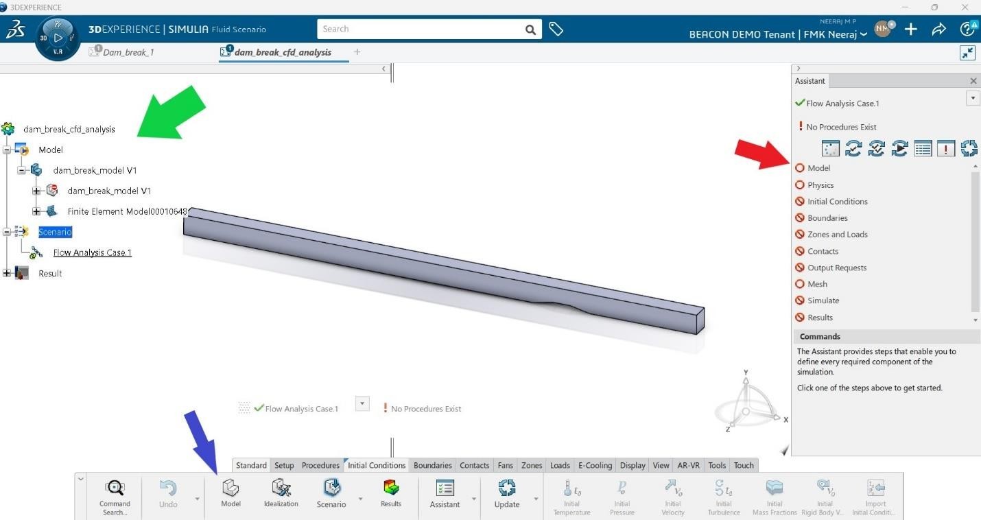
The window consists of simulation tree (green arrow), the guided user assistant (red arrow) and the action bar. The advantage of fluid dynamics engineer is the presence of guided user assistant. It shows what are the steps to be defined, and whether any errors are there in any definition of model and scenario. The workflow can also be taken through action bar. However, we are going to pursue the easier way by using the user assistant. Click on model in the user assistant.
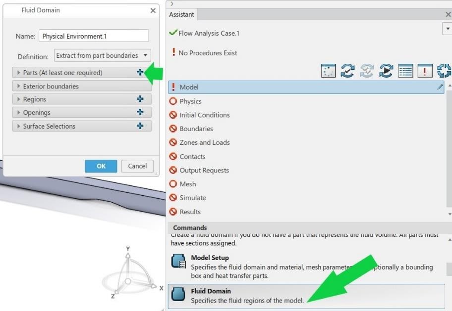
After clicking on model, lot of options such as model setup, fluid domain, fluid section, solid section, VOF, porous, multispecies section are visible at bottom part of assistant. As the first part of preprocessing, we create the fluid domain. Click on fluid domain and then in the dialogue box, click ‘+’ on parts.
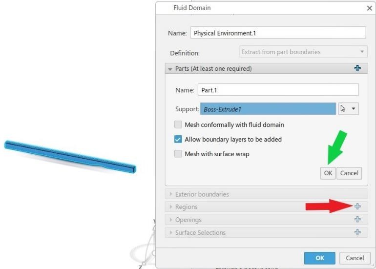
In the part section, select the geometry by either dragging the mouse over it or by just clicking on it. The dragging is useful when more than one part is involved. Make sure that ‘allow boundary layers to be added’ dialogue is checked. Now click ok and then click ‘+’ right to region where we will define the fluid region. Leave the exterior boundaries section unchecked since the flow is assumed to be internal.
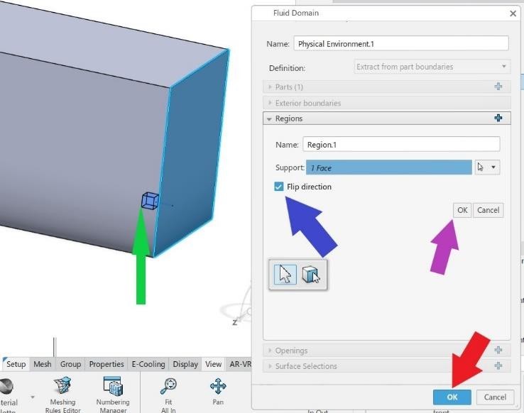
In the regions section, select any face of the body as support and rectangular glyph will be shown (green arrow). This represents the fluid region. We know that fluid is inside the model. Hence, make sure that glyph is inside the model by checking flip direction. Now click ok in the regions section and then in fluid domain dialogue box.
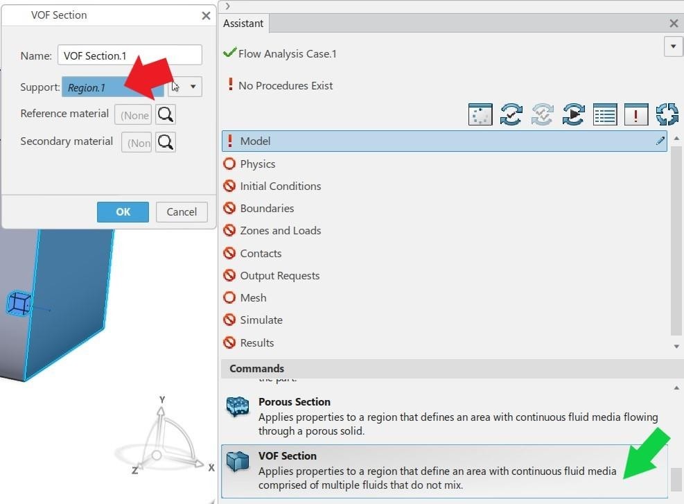
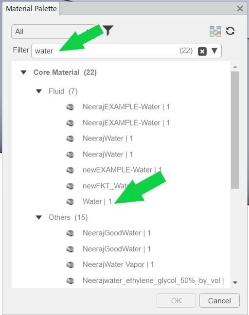
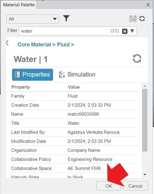
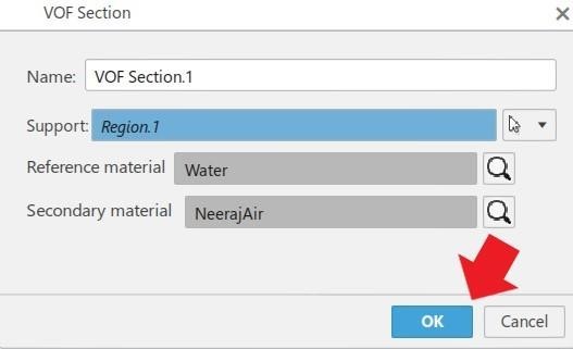
Going back to the model section in user assistant, click on VOF section. In the VOF dialogue box, select the defined fluid region as support (click on blue glyph). Now select water as reference fluid and air as secondary fluid (In case of VOF simulation, denser fluid is selected as reference fluid). When you click on the magnifying glass icon, the material palette will be open. Search for water in the search bar and select water and click ok. Repeat the same for selecting air as secondary fluid (make sure that you have downloaded the optional content and updated 3DEXPERIENCE platform for accessing all materials).
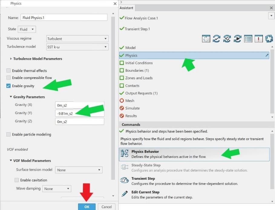
The fluid model is defined fully now. A green tick mark left to model in user assistant confirms the same. Now, the fluid Physics must be defined. Click on Physics and section and keep default SST k-ω as the turbulence model and read different effects such as thermal, compressible flow, gravity and particle modelling etc. The thermal, compressible flow and particle modelling should remain unchecked since both effects are not studied here. However, the fluid flow in dam break is primarily affected by gravity, hence it must be turned on and a negative acceleration due to gravity (9.81 m/s2) is given in y direction. It should also be noted that the VOF parameters are turned on in the Physics dialogue box since a VOF section is defined. Please expand it and observe that surface tension model is not used since the same is not used in the reference study also. After that click ‘ok’.
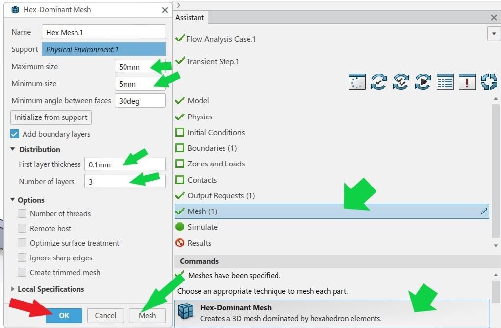
It is observable from user assistant that a green tick has come to left side of Physics section. Now the meshing of VOF section must be carried out. There are several types of body fitted meshes available in fluid dynamics engineer such as Hex-dominant, tetrahedron, octree-tetrahedron, sweep-3D, surface meshes etc. For fluid region, Hex dominant mesh is predominantly used. Click on mesh in assistant and then Hex-dominant mesh. In the next dialogue box, specify the maximum and minimum size as 50 and 5 mm respectively since the same is used in reference study also. Create 3 boundary layers with 0.1 mm thickness. Click on mesh and meshing will start. After completion, click ‘ok’.
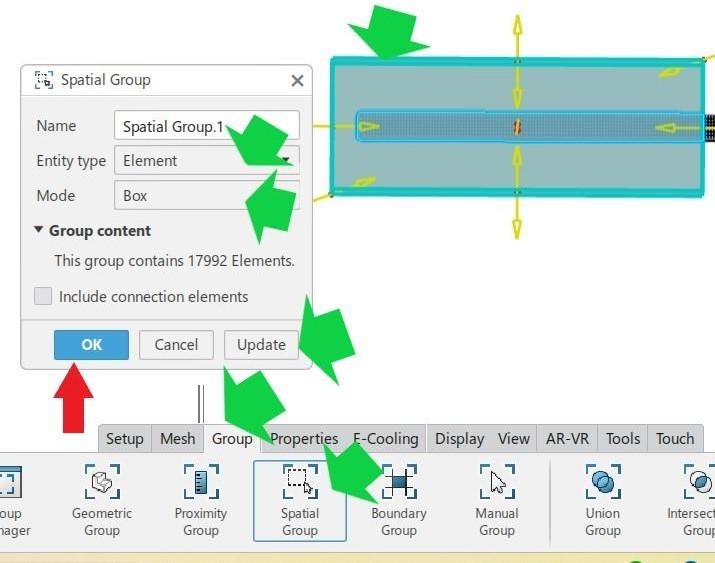
Moving on, we must create initial conditions for the water column (the volume fraction of water column should be defined as 1). For this a spatial group must be created. Go to the action bar below and click on group. From the group section, select spatial group. In the dialogue box, select element and then select box. Now drag over half part of the model as shown in figure and then click ‘update’ and ‘ok’. The spatial group has been created now.
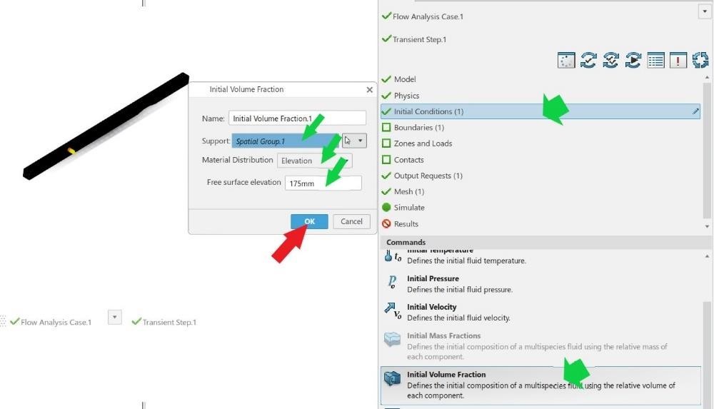
Using the spatial group the initial condition of water column can be given (reservoir). Click on initial conditions in the assistant. Click on initial volume fraction below and in the popping up dialogue box, select the created spatial group (spatial group 1) as the support from simulation tree (from groups). Change volume fraction to elevation (here we can define the height of water column). The origin is above the obstruction which is 750 mm high. Hence elevation of 175 mm should be given to make the water column height as 250 mm as per the reference model. Click ‘ok’ finally.
Model and conditions are defined along with the mesh generation.
Lesson 2 is finished.
We Urge You To Call Us For Any Doubts & Clarifications That You May Have. We Are Eager to Talk To You
Call Us: +91 7406663589
 (No Ratings Yet)
#365/8, Ground Floor, "Hasmitha Avenue", 16th Main, 4th T Block East, Jayanagar, 4th T Block East, Pattabhirama Nagar, Jayanagar, Bengaluru, Karnataka 560041
Rated 4.7/5 with a total of 62 reviews
"CARAX" Building 4th Floor, 105/1/1/4, Next to Radha Hotel, Pune-Mumbai Xpress Way,Baner,Pune 411045
Rated 4.7/5 with a total of 17 reviews
801, 8th Floor, LODHA Supremus, I-Think Techno Campus,Kanjurmarg EAST - MUMBAI, MH, India – 400042.
Rated 5/5 with a total of 51 reviews
501, 5th Floor, Connekt Coworking Space, Gala Argos, Netaji Rd, Ellisbridge, Ahmedabad, Gujarat 380006
Rated 4.1/5 with a total of 7 reviews
Best Engineering Aids & Consultancies Pvt. Ltd. No 306, Karunaa Conclave, 3rd Floor, AD Block, Shanthi Colony, Anna Nagar, Chennai - 600040
Rated 4.6/5 with a total of 16 reviews
Flat no F1, first floor, Nakhate corner, Eknath rang mandir road,New Usmanpura, Aurangabad, 431005.
A-101, 1st Floor, The Hub Complex, opp. Shete Hospital, Mahatma Nagar, Parijat Nagar, Nashik, Maharashtra 422005.
Best Engineering Aids & Consultancies Pvt Ltd (BEACON) Wellwork Workspaces, L1 - 1017A,B, Lower Ground Floor,Vasavi MPM Grand, Ameerpet, Hyderabad, Telangana 500073