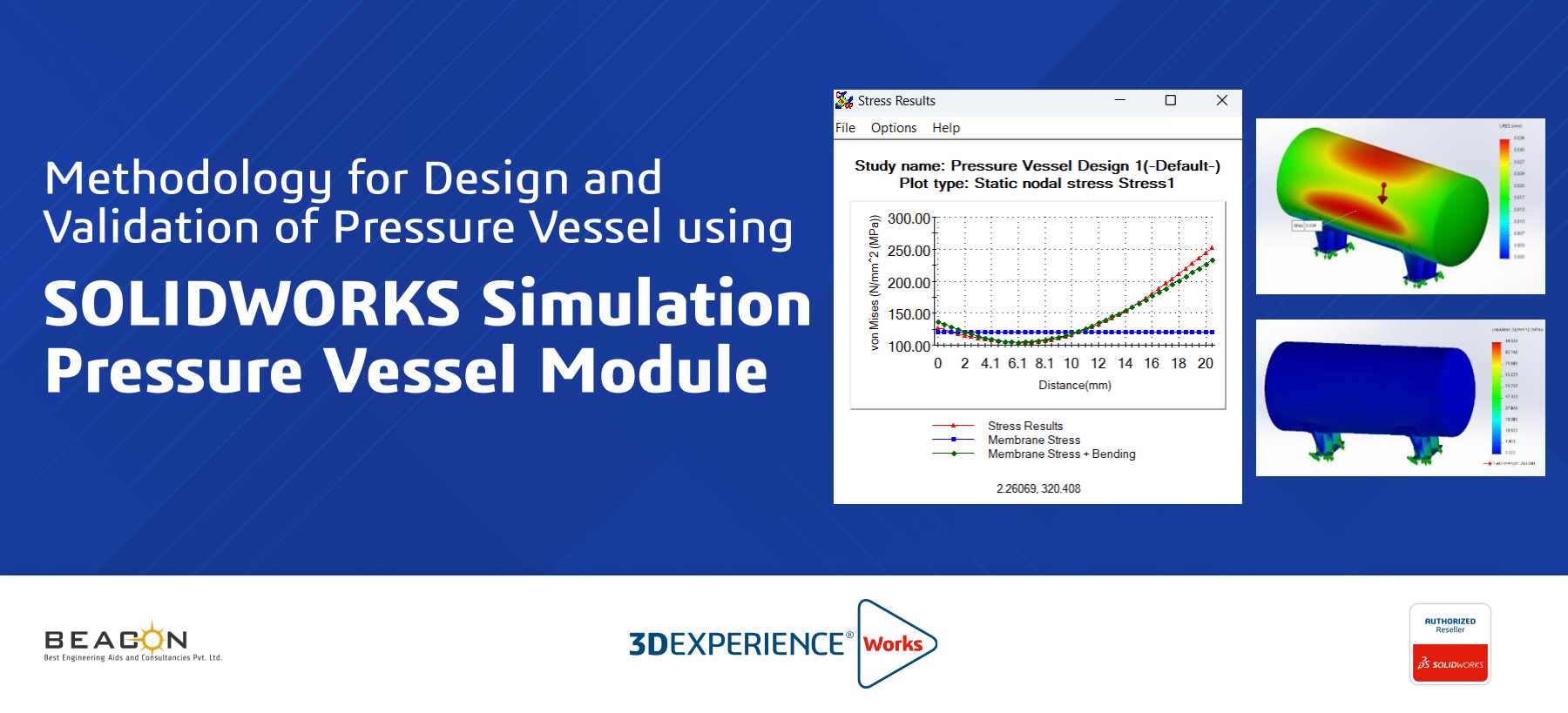


1. Introduction to Pressure Vessels and SOLIDWORKS Simulation
Pressure vessels are vital in industries like oil and gas, storing fluids under pressure. Safety is paramount, guided by standards like ASME BPVC. SOLIDWORKS Simulation’s Pressure Vessel Design Module helps analyze stress and deformation, ensuring compliance. Key to this is stress linearization, separating stresses into components to verify they meet allowable limits. This module streamlines the process, enhancing safety and reliability.
2. Problem Definition
Leading pressure vessel manufacturer needs to assess a high-pressure steam drum for a cogeneration plant. Operating at 2 MPA and 75°C, the drum, made of SA-516 Grade 70 steel, will experience pressure, gravity, and thermal stresses. The goal is to ensure safety and reliability while complying with ASME BPVC.
3. Simulation setup
Boundary Conditions and External Load Fixtures:
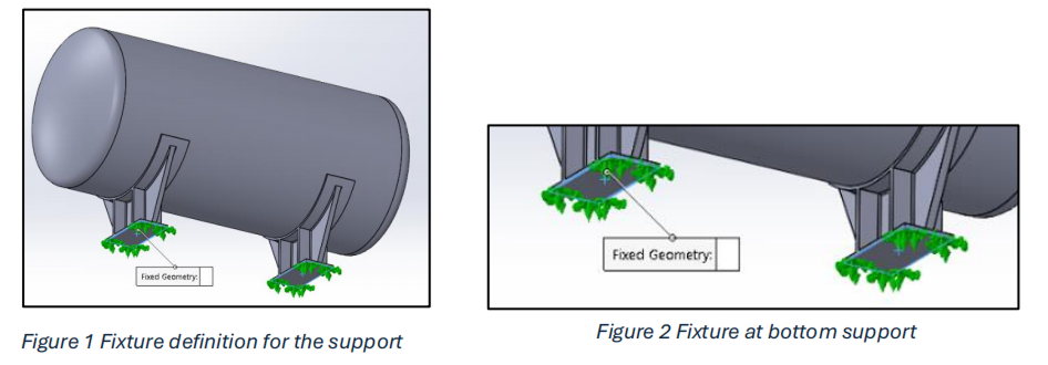
A fixed constraint is applied to the faces at the bottom of both support plates, preventing any displacement or rotation in those directions.
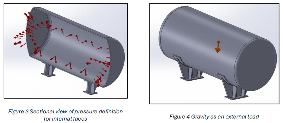
External load:
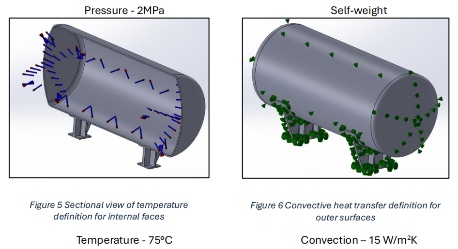
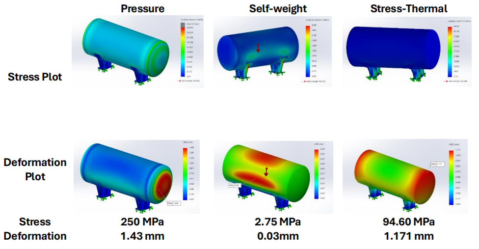
A pressure load of 2 MPA (20 bar) is applied to the vessel’s internal surfaces. Additionally, a thermal load representing a 75°C temperature rise is applied internally with convection coefficient of 15 W/m2K. Finally, the weight of the vessel is considered by applying a gravity load. These loads are then superimposed and analyzed within the Pressure Vessel module to assess the combined stress state.
Pressure Vessel Details:
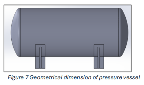
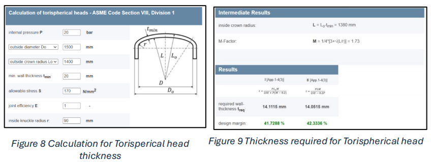
Refer the site calculation for Torispherical head thickness:
https://www.cis-inspector.com/asme-code-calculation-kloepperboden.html
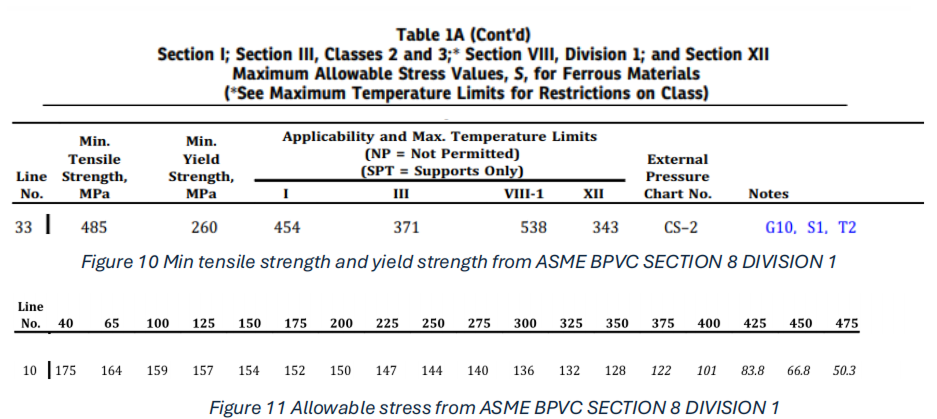
Required Wall Thickness (treq):
This calculation determines the minimum required wall thickness for a torispherical pressure vessel head to safely withstand the specified internal pressure according to the ASME Code. The results show that the initial estimated wall thickness of 20 mm is significantly higher than the required thickness, indicating a substantial design margin.
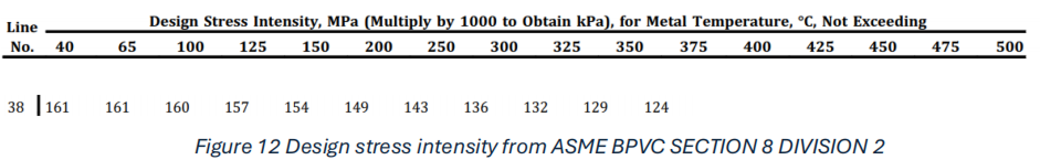
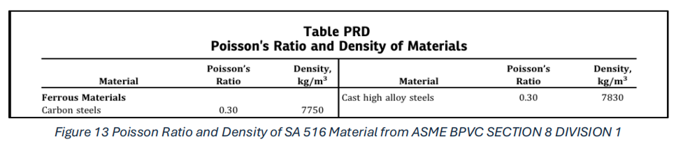
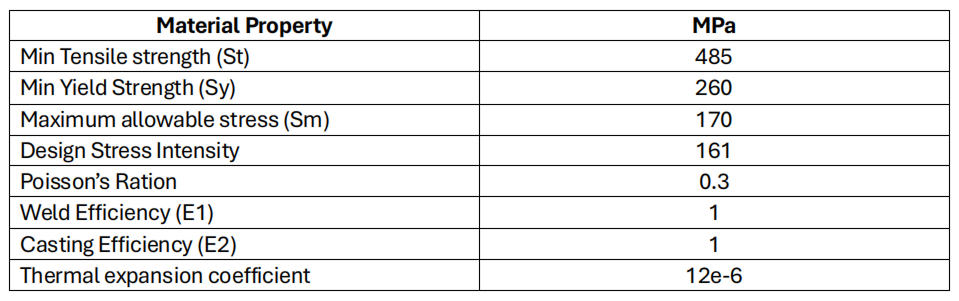
4.Material property (ASME BPVC Code SECTION VIII DIVISION I &II)
SA-516 Grade 70
SA-516 is a high-strength, low-alloy steel renowned for its suitability in demanding pressure vessel applications, particularly those operating at elevated temperatures. This material excels due to its impressive combination of strength, toughness, and resistance to creep and fatigue.
Key Advantages of Using SA-516:
SA-516 offers high strength, excellent weldability, and maintains integrity at elevated temperatures. This industry-standard material enables cost-effective, reliable pressure vessel designs that meet ASME BPVC requirements.
By selecting SA-516 for our analysis, we can accurately model the vessel’s behavior under operating conditions, ensuring the design meets the highest safety and performance standards. Material properties for SA-516 were determined based on the relevant ASME BPVC code provisions for the specified operating temperature of 75°C.
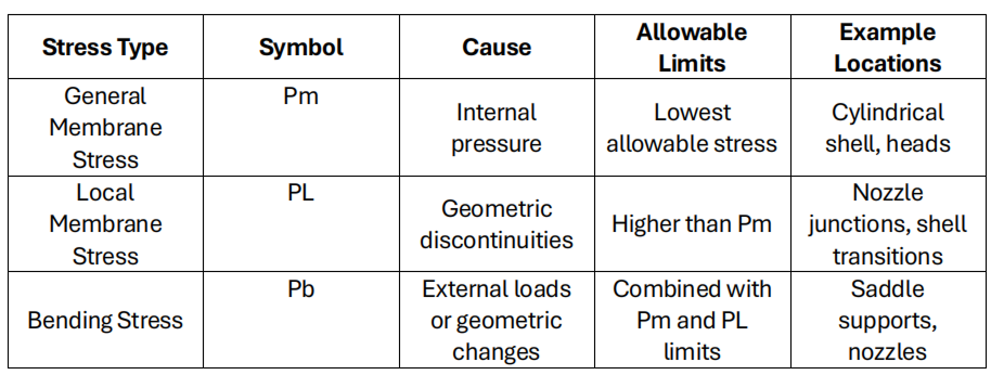
5.Stress Categorization and Code Compliance (ASME Section VIII, Division 2):
Imagine a pressure vessel as a sturdy container holding fluids or gases under pressure. The forces within and around this vessel create different types of stress that engineers must carefully analyze.
Understanding these stress types is crucial for ensuring the safety and reliability of pressure vessels.
Stress Categories (Per ASME Code):
Terminologies
Comments:
Mesh Details

A high-quality solid mesh with over 6 million nodes and 4 million elements was generated using a blended curvature-based approach. Element size was controlled to meet quality criteria (aspect ratio < 3), ensuring suitability for accurate simulation within SOLIDWORKS. 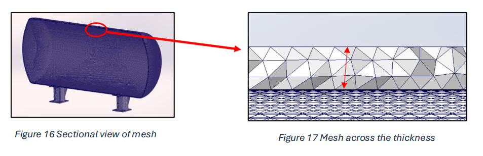
6.RESULTS:
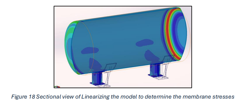
Linearized Results with PVD Module
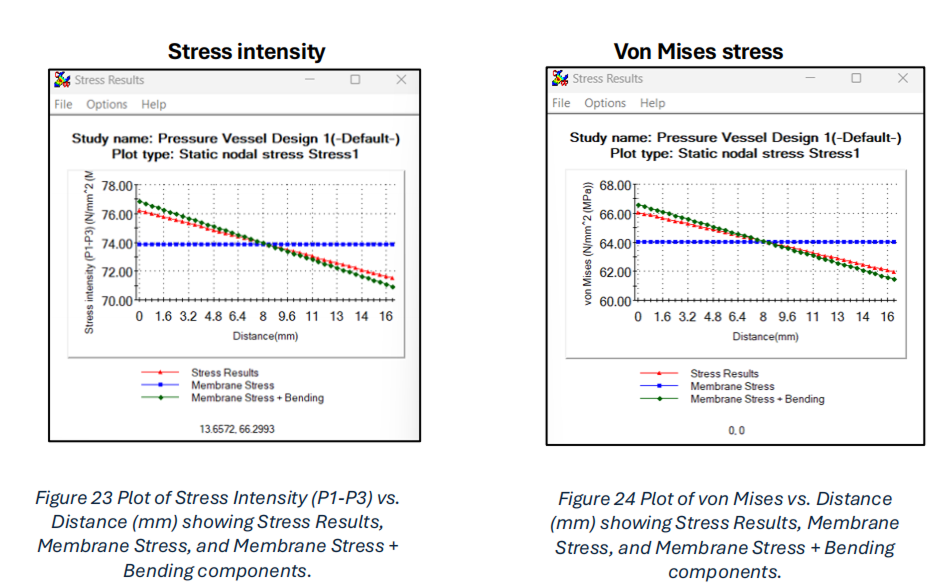
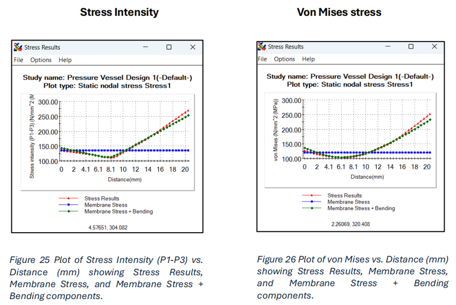
Stress linearization separates the bending and membrane stress components from the actual stress distribution observed through the thickness of a wall in a sectional stress plot of a pressure vessel study.
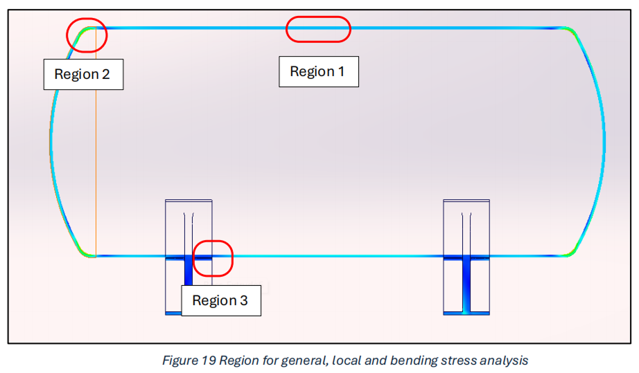
Regions for General, Local and Bending stress analysis
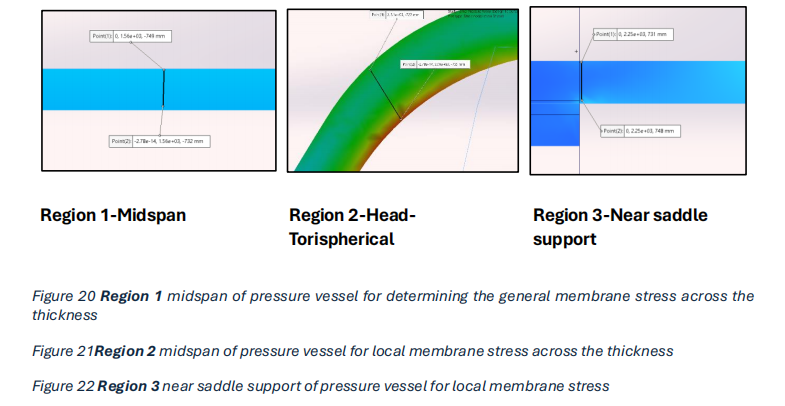
Linearize Stress variation results across thickness
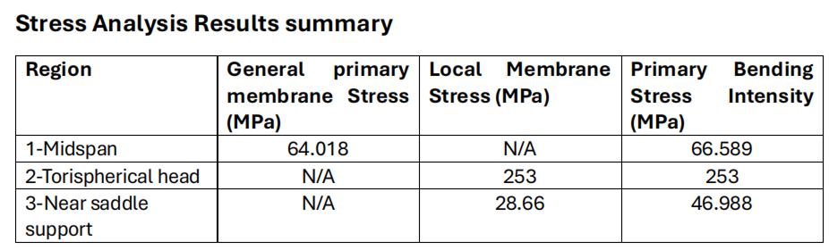
1.General Membrane Stress (Pm) at location “midspan”.
2.Local membrane stress limit (geometric discontinuity (Head-Torispherical)
3.Local membrane stress limit (Near Saddle Support)
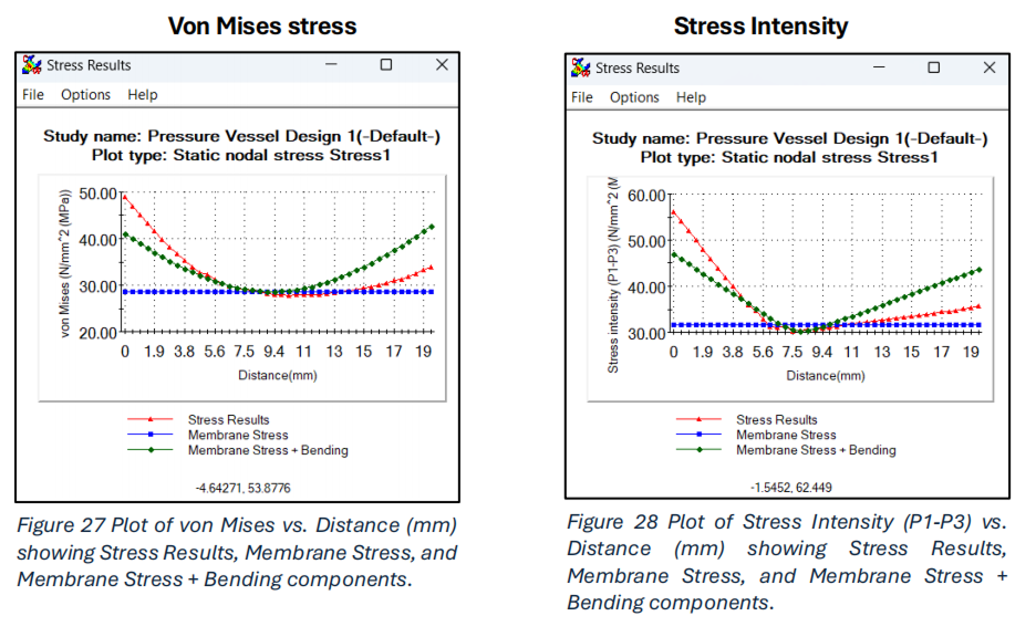
Stress Analysis Results summary
Conclusion:
This study demonstrates the methodology for the Pressure Vessel module for the analysis of pressure vessels and effectiveness of using SOLIDWORKS Simulation. The incorporation of stress linearization and the consideration of multiple load scenarios provide a robust and accurate assessment of the vessel’s safety and compliance with the ASME BPVC code. This approach can be valuable for engineers in designing and optimizing pressure vessels for various applications.
References
1.ASME Boiler and Pressure Vessel Code (BPVC) Section VIII:
2.ASME Boiler and Pressure Vessel Code, Section II:
3.SA-516 Grade 70 Material Specifications:
4.SOLIDWORKS Simulation Manual:
5.Pressure Vessel Design and Analysis:
6.https://www.cis-inspector.com/asme-code-calculation-kloepperboden.html
We Urge You To Call Us For Any Doubts & Clarifications That You May Have. We Are Eager to Talk To You
Call Us: +91 7406663589
 (No Ratings Yet)
#365/8, Ground Floor, "Hasmitha Avenue", 16th Main, 4th T Block East, Jayanagar, 4th T Block East, Pattabhirama Nagar, Jayanagar, Bengaluru, Karnataka 560041
Rated 4.7/5 with a total of 62 reviews
"CARAX" Building 4th Floor, 105/1/1/4, Next to Radha Hotel, Pune-Mumbai Xpress Way,Baner,Pune 411045
Rated 4.7/5 with a total of 17 reviews
801, 8th Floor, LODHA Supremus, I-Think Techno Campus,Kanjurmarg EAST - MUMBAI, MH, India – 400042.
Rated 5/5 with a total of 51 reviews
501, 5th Floor, Connekt Coworking Space, Gala Argos, Netaji Rd, Ellisbridge, Ahmedabad, Gujarat 380006
Rated 4.1/5 with a total of 7 reviews
Best Engineering Aids & Consultancies Pvt. Ltd. No 306, Karunaa Conclave, 3rd Floor, AD Block, Shanthi Colony, Anna Nagar, Chennai - 600040
Rated 4.6/5 with a total of 16 reviews
Flat no F1, first floor, Nakhate corner, Eknath rang mandir road,New Usmanpura, Aurangabad, 431005.
A-101, 1st Floor, The Hub Complex, opp. Shete Hospital, Mahatma Nagar, Parijat Nagar, Nashik, Maharashtra 422005.
Best Engineering Aids & Consultancies Pvt Ltd (BEACON) Wellwork Workspaces, L1 - 1017A,B, Lower Ground Floor,Vasavi MPM Grand, Ameerpet, Hyderabad, Telangana 500073