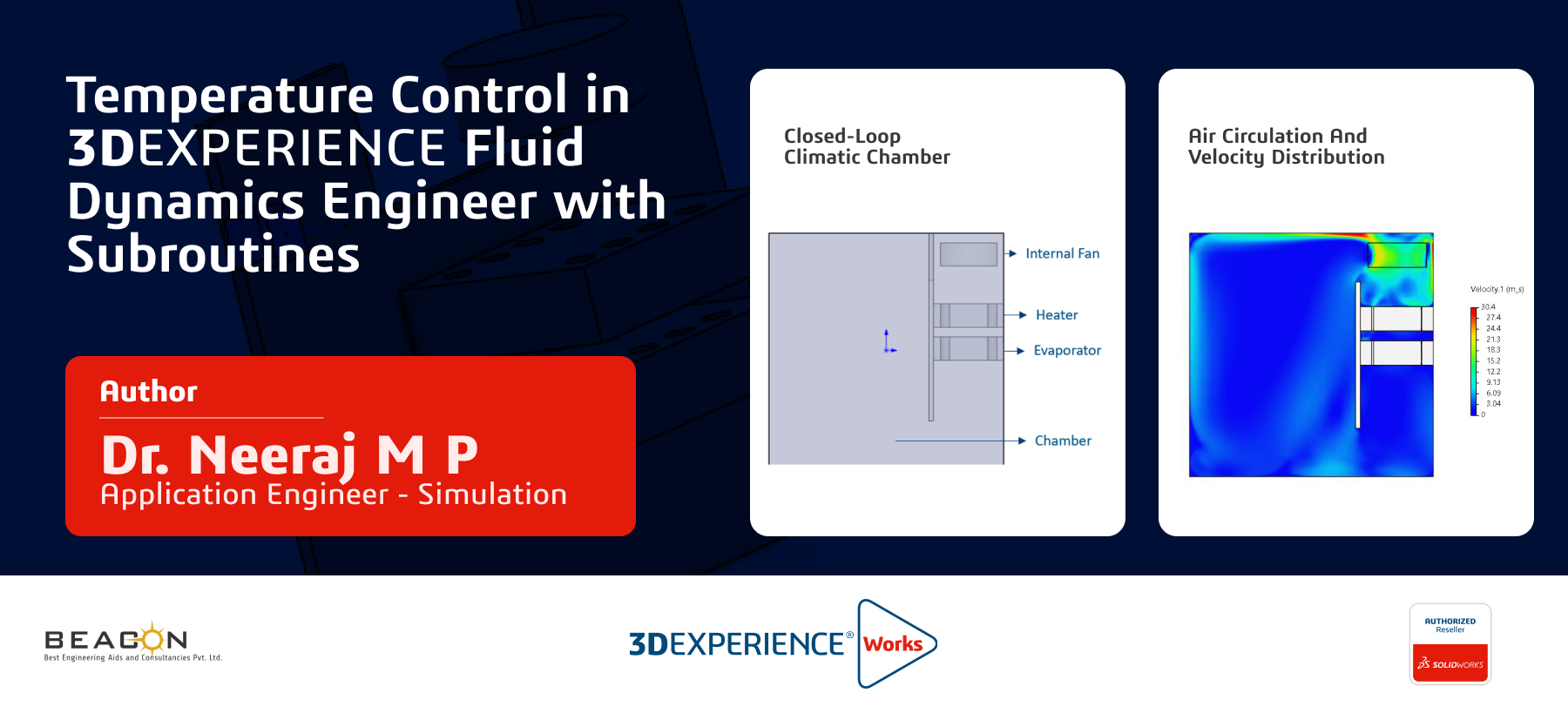


In modern thermal system simulations, precise temperature control is critical, especially in applications like climatic chambers used for environmental testing. This blog explores how JavaScript subroutines can be used within 3DEXPERIENCE Fluid Dynamics Engineer to regulate heat sources dynamically over time. The analysis focuses on a closed-loop climatic chamber featuring three key components—an evaporator, a heater, and an internal circulation fan— strategically placed on one side of the chamber (Refer to figure below). The opposite side contains only air, with circulation driven by the fan. Using custom JavaScript subroutines, time-dependent, temperature dependent heat source profiles are applied to the evaporator and heater, enabling real- time control of the internal temperature conditions. This setup replicates realistic thermal management scenarios and demonstrates the power of programmable control in CFD environments.
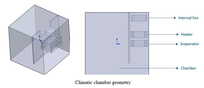
The climatic chamber operates by actively regulating the internal air temperature through the coordinated functioning of the evaporator, heater, and internal fan. Positioned on one side of the closed chamber, the evaporator and heater serve as the primary cooling and heating elements, respectively. The evaporator absorbs heat from the surrounding air, reducing its temperature, while the heater supplies thermal energy when heating is required. An internal fan circulates air between the conditioned side—where the evaporator and heater are located—and the opposite side of the chamber, which initially contains only air. This circulation ensures uniform temperature distribution throughout the chamber. By modulating the heat input to the evaporator and heater over time using programmable subroutines, the system can replicate complex thermal profiles, simulating real-world environmental conditions with high precision.
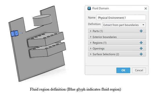
Now, let’s explore how the corresponding CFD-based thermal simulation is performed using 3DEXPERIENCE Fluid Dynamics Engineer. The process begins with seamless CAD integration, where the chamber geometry—originally modeled in SolidWorks—is directly transferred into the simulation environment. The fluid domain is automatically extracted with a single click, streamlining the preprocessing workflow. Within this domain, two distinct fluid sections are defined to represent the airflow zones across the chamber. Notably, the internal fan is treated as a separate fluid section to accurately capture its rotating influence on the airflow. This setup ensures precise modeling of fluid movement and thermal exchange across the evaporator, heater, and fan-driven regions, forming the basis for a high-fidelity thermal analysis. Corresponding solid sections (Aluminum) are defined for both evaporator and heater bodies.
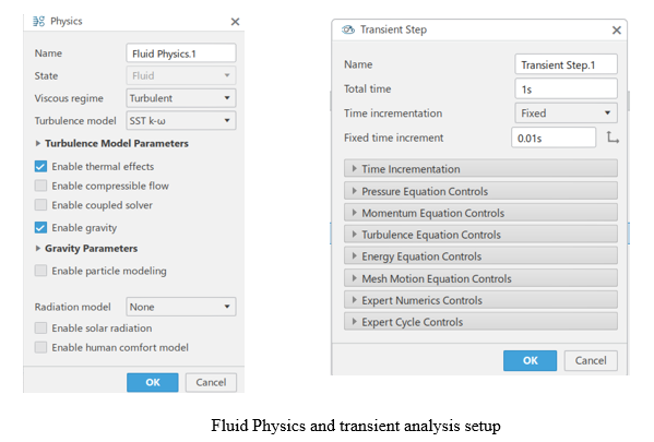
With the geometry and fluid sections defined, the next step involves configuring the Physics and simulation scenarios. For turbulence modeling, the SST k-ω model is selected due to its proven accuracy in capturing near-wall behavior and its robustness in heat transfer and thermal convection scenarios. This makes it particularly well-suited for simulating the complex flow and temperature gradients within the climatic chamber. A transient (time-dependent) analysis is employed to capture the dynamic response of the system over time, allowing for the implementation of time- varying heat sources. The complete transient simulation setup is illustrated in the figure below.
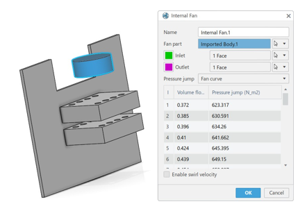
The internal fan is configured by selecting the corresponding fan body and defining its inlet and outlet flow surfaces to establish the direction of airflow. A fan performance curve, representing the relationship between pressure rise and volumetric flow rate, is also specified to accurately simulate the fan’s behavior within the system.
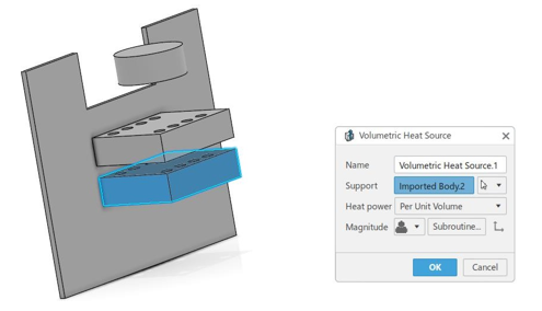
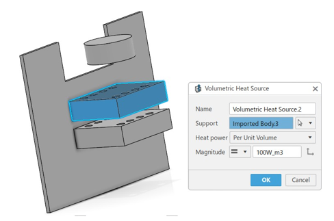
One of the most critical aspects of this simulation is temperature control, which is achieved through the implementation of user-defined subroutines. These subroutines, written in JavaScript, allow for dynamic control of the volumetric heat sources based on time or temperature-dependent logic. By linking these scripts to the heater and evaporator components, the simulation can replicate realistic thermal regulation behavior. The configured volumetric heat sources and their corresponding JavaScript subroutines are presented below.
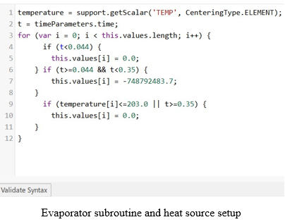
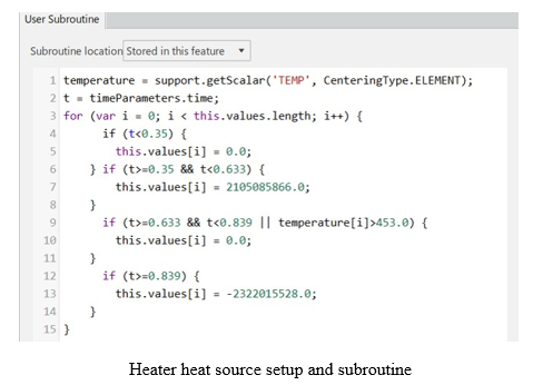
The evaporator begins operation at 0.044 seconds, initiating heat absorption from the surrounding air. As a result, its temperature gradually decreases and reaches 203 K by 0.35 seconds, at which point the evaporator is turned off. Immediately following this, the heater is activated, supplying heat and increasing its temperature up to 453 K. Once this target temperature is reached, the heater is turned off temporarily to prevent overheating. Subsequently, at 0.839 seconds, the heater begins to absorb heat from the surroundings, allowing its temperature to decrease back to 298 K. This entire sequence of events is implemented using two dedicated JavaScript subroutines linked to the respective volumetric heat sources of the evaporator and heater. The simulation is executed in the cloud using the default configuration of 16 computational cores, ensuring efficient and scalable performance. The simulation results are discussed in the following section.
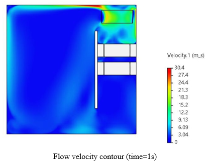
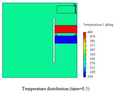
Air circulation and velocity distribution within the chamber are governed by the internal fan, which ensures uniform mixing and transport of heated or cooled air across the domain. The temperature distribution at 0.5 seconds which shows uniform temperature distribution at the conditioning side (left side), as shown above, highlights the thermal gradients resulting from the combined effect of the evaporator, heater, and airflow. To verify the effectiveness of the temperature control strategy, history plots of surface-averaged temperatures on both the evaporator and heater surfaces are monitored over time. These plots, shown below, confirm whether the desired thermal setpoints are achieved and maintained during the simulation.
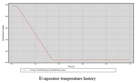
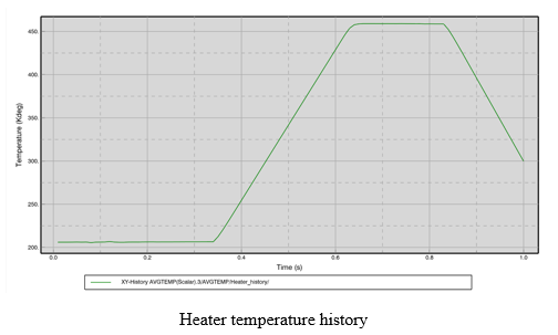
The history plots clearly demonstrate that temperature control has been successfully achieved in accordance with the logic defined in the attached JavaScript subroutines. This validates the effectiveness of using programmable heat source control for dynamic thermal management. The approach outlined here can be further extended to support more advanced and customized thermal CFD analyses within 3DEXPERIENCE Fluid Dynamics Engineer, enabling simulation of real- world scenarios such as thermostat-driven heating, cooling cycles, or feedback-controlled thermal systems.
We Urge You To Call Us For Any Doubts & Clarifications That You May Have. We Are Eager to Talk To You
Call Us: +91 7406663589
 (1 votes, average: 5.00 out of 5)
#365/8, Ground Floor, "Hasmitha Avenue", 16th Main, 4th T Block East, Jayanagar, 4th T Block East, Pattabhirama Nagar, Jayanagar, Bengaluru, Karnataka 560041
Rated 4.7/5 with a total of 62 reviews
"CARAX" Building 4th Floor, 105/1/1/4, Next to Radha Hotel, Pune-Mumbai Xpress Way,Baner,Pune 411045
Rated 4.7/5 with a total of 17 reviews
801, 8th Floor, LODHA Supremus, I-Think Techno Campus,Kanjurmarg EAST - MUMBAI, MH, India – 400042.
Rated 5/5 with a total of 51 reviews
501, 5th Floor, Connekt Coworking Space, Gala Argos, Netaji Rd, Ellisbridge, Ahmedabad, Gujarat 380006
Rated 4.1/5 with a total of 7 reviews
Best Engineering Aids & Consultancies Pvt. Ltd. No 306, Karunaa Conclave, 3rd Floor, AD Block, Shanthi Colony, Anna Nagar, Chennai - 600040
Rated 4.6/5 with a total of 16 reviews
Flat no F1, first floor, Nakhate corner, Eknath rang mandir road,New Usmanpura, Aurangabad, 431005.
A-101, 1st Floor, The Hub Complex, opp. Shete Hospital, Mahatma Nagar, Parijat Nagar, Nashik, Maharashtra 422005.
Best Engineering Aids & Consultancies Pvt Ltd (BEACON) Wellwork Workspaces, L1 - 1017A,B, Lower Ground Floor,Vasavi MPM Grand, Ameerpet, Hyderabad, Telangana 500073