


In the previous 2 lessons, we learned about setting up the globe valve model for simulation and creating scenarios such as fluid physics and boundary conditions along with meshing using 3DEXPERIENCE fluid dynamics engineer. (lesson 1) and postprocessing and results analysis (lesson 2). In this lesson, we are going to discuss how a design change in the model in SOLIDWORKS can be incorporated in 3DEXPERIENCE Fluid Dynamics Engineer.
The advantage of connection between SOLIDWORKS and 3DEXPERIENCE Fluid Dynamics Engineer (MODSIM approach) is that any design change in SOLIDWORKS can be easily updated in the platform with just one click. Also, we don’t have to reset the model setup like in conventional simulation software. Let’s take a dig into that.
Download the CAD model from the following link.
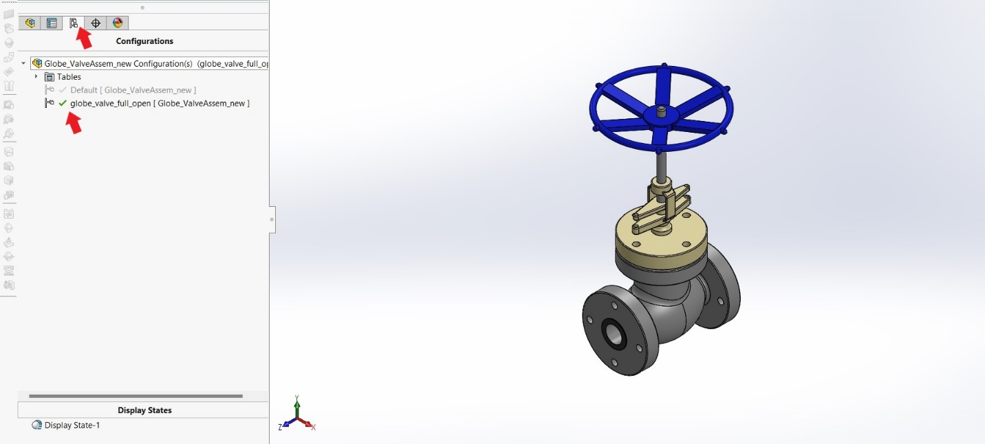
Open the model and select (double click) the ‘globe_valve_full_open’ configuration from the configuration manager.
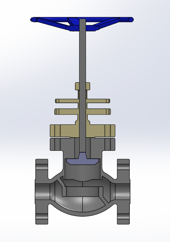
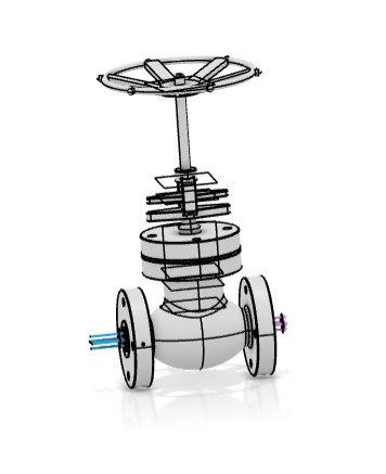
From sectional view, it is visible that the plug is on the top side and valve is in full open condition.
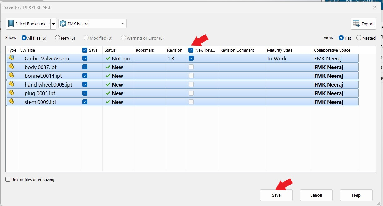
Now go to 3D task pane and select ‘save active window’ and in the save dialogue box select new revision and save.
Now see that all components are saved in 3D task pane (green tick mark).
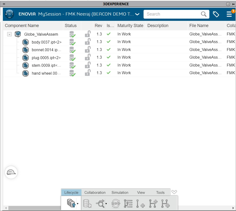
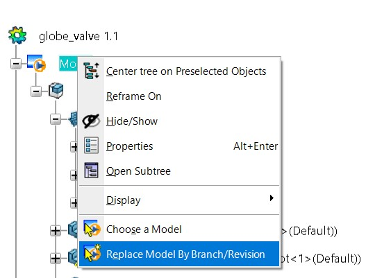
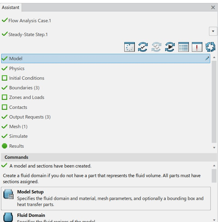
Please go to the already opened 3DEXPERIENCE Fluid Dynamics Engineer window. Right click on ‘model’ in the simulation tree and select ‘replace model by branch/revision’ option.
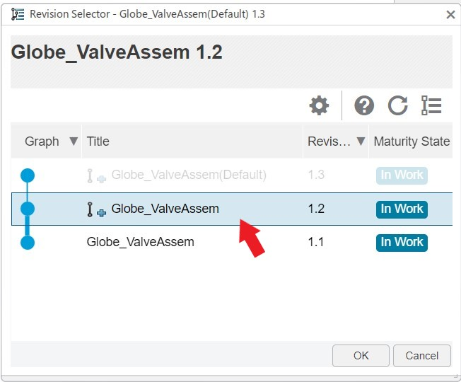
Select new model as shown below and click ‘ok’.
It should be observable that the model in GUI has changed.
It should be also noted that, the assistant remains the same and we don’t have to setup the analysis again.
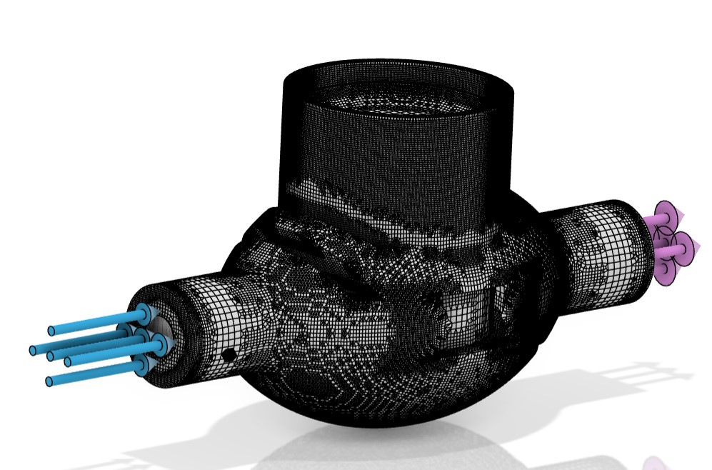
Please update and visualize the mesh. The updated mesh is shown below.
Now we can go into the simulation dialogue box and select cloud simulation.
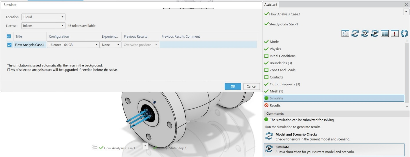
Run and complete the simulation and then click on ‘results’ for the post processing. The results are shown below.
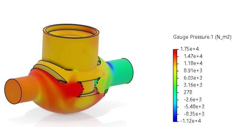
Gauge pressure contour
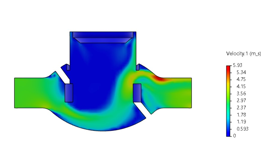
Velocity contour (section plot)
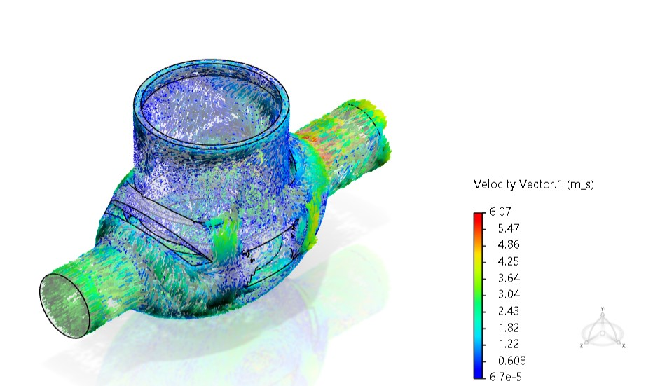
Velocity vector plot
It should be noted that the gauge pressure drop has reduced for the full open condition. The pressure drop parameter was already created in the previous study (Refer to lesson-2). Let’s see the change in this parameter from simulation tree.
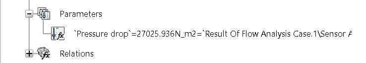
The pressure drop is around 0.027 Mpa which is very less compared to the 0.161 Mpa in the previous study. The valve is in fully open condition now and it provides an uninterrupted flow path. This may be the reason behind it.
From this lesson, it is understood that how easy is to integrate a design change in SOLIDWORKS to 3DEXPERIENCE platform.
Lesson 3 is finished.
We Urge You To Call Us For Any Doubts & Clarifications That You May Have. We Are Eager to Talk To You
Call Us: +91 7406663589
 (No Ratings Yet)
#365/8, Ground Floor, "Hasmitha Avenue", 16th Main, 4th T Block East, Jayanagar, 4th T Block East, Pattabhirama Nagar, Jayanagar, Bengaluru, Karnataka 560041
Rated 4.7/5 with a total of 62 reviews
"CARAX" Building 4th Floor, 105/1/1/4, Next to Radha Hotel, Pune-Mumbai Xpress Way,Baner,Pune 411045
Rated 4.7/5 with a total of 17 reviews
801, 8th Floor, LODHA Supremus, I-Think Techno Campus,Kanjurmarg EAST - MUMBAI, MH, India – 400042.
Rated 5/5 with a total of 51 reviews
501, 5th Floor, Connekt Coworking Space, Gala Argos, Netaji Rd, Ellisbridge, Ahmedabad, Gujarat 380006
Rated 4.1/5 with a total of 7 reviews
Best Engineering Aids & Consultancies Pvt. Ltd. No 306, Karunaa Conclave, 3rd Floor, AD Block, Shanthi Colony, Anna Nagar, Chennai - 600040
Rated 4.6/5 with a total of 16 reviews
Flat no F1, first floor, Nakhate corner, Eknath rang mandir road,New Usmanpura, Aurangabad, 431005.
A-101, 1st Floor, The Hub Complex, opp. Shete Hospital, Mahatma Nagar, Parijat Nagar, Nashik, Maharashtra 422005.
Best Engineering Aids & Consultancies Pvt Ltd (BEACON) Wellwork Workspaces, L1 - 1017A,B, Lower Ground Floor,Vasavi MPM Grand, Ameerpet, Hyderabad, Telangana 500073